Pakole ZENIT-12 Series User manual

ZENIT TYPE TUBE RADIANT HEATER Contents
Table of Contents
1. ............................................................................................... 3
2. .............................................................................................4
Installer’s responsibilities �������������������������������������������������������������������������������������������������������������� 4
Data board ������������������������������������������������������������������������������������������������������������������������������������ 4
Corrosive materials ����������������������������������������������������������������������������������������������������������������������� 5
Standards and laws ���������������������������������������������������������������������������������������������������������������������� 5
Safety signs ���������������������������������������������������������������������������������������������������������������������������������� 5
Safe usage������������������������������������������������������������������������������������������������������������������������������������ 5
3. ............................................................... 6
4. .............................................................................................. 6
5. ............................................................................................................7
Components of „I” -form tube radiant heater��������������������������������������������������������������������������������� 7
Components of „U”-form tube radiant heater �������������������������������������������������������������������������������� 7
Appliance installation �������������������������������������������������������������������������������������������������������������������� 8
Gas connection ����������������������������������������������������������������������������������������������������������������������������� 8
Electrical connection ��������������������������������������������������������������������������������������������������������������������� 8
Optional thermostats, regulators��������������������������������������������������������������������������������������������������� 9
Control of appliance ���������������������������������������������������������������������������������������������������������������������� 9
Heat-radiated area ������������������������������������������������������������������������������������������������������������������������ 9
Protective distances�������������������������������������������������������������������������������������������������������������������� 10
Combustion-air supply ��������������������������������������������������������������������������������������������������������������� 12
6. .............................................................. 12
7. ........................................................................................... 13
8. ..................................................................................... 13
Start, restart �������������������������������������������������������������������������������������������������������������������������������� 13
Operation of automatic burner control (HONEYWELL S4965R)������������������������������������������������� 13
Operation of automatic burner control (SIT 579 DBC)���������������������������������������������������������������� 14
9. ......................................................................................................... 15
Check at the beginning of season����������������������������������������������������������������������������������������������� 15
Maintenances������������������������������������������������������������������������������������������������������������������������������ 15
Maintenance supervisions by a qualified service department����������������������������������������������������� 16
Gas change��������������������������������������������������������������������������������������������������������������������������������� 16
10. ............................................................................................... 16
11............................................................................................................. 17
Enclosure 1�: Variety-list of ZENIT-type tube radiant heaters, length, weight ����������������������������� 17
Enclosure 2�: Heating and consumption values of ZENIT-type tube radiant heaters������������������ 18

ZENIT TYPE TUBE RADIANT HEATER User’s Manual
3
The ZENIT-type tube radiant heater appliances have been developed and certified in compliance with EN 416 standard and qualified for
heating of industrial rooms! The function of these heater appliances to ensure heating of appointed workplace temporarily or continu-
ously! In case of proper using the appliance guarantees safety and energy-saving operation! The combustion products issued during
combustion process leave through the flue system into the open air� In case of further possible questions regarding the applicability
please turn to the local Fire Protection Office!
Other standards can give you directions in terms of proper using of natural and propane gas as follows: leading/piping, storing etc�! Con-
cerning the detailed content of these standards the local Bureau of Standards can help�
Carbon- monoxide poisoning: The initial symptoms of carbon-monoxide poisoning are similar to influenza namely headache, dizziness
and/or nausea! If these symptoms are observed in that case the appliance probably does not work satisfactorily! First of all go fresh air,
ventilate the rooms and have the appliance investigated!
Propane-gas: The propane-gas odourless! Mercaptan-derivative as scented component is mixed into the gas to be able to observe the
possible escape! In spite of the typical smell is not felt the propane gas can be present in the environmental air in case of escaping!
GENERAL SAFETY NOTICES
-
death!
-
-
-
1.

ZENIT TYPE TUBE RADIANT HEATER User’s Manual
4
Make sure that read and understood all the warnings, correct keeping of which can guarantee the safety and faultless operation!
During the installation be always circumspect! Follow the valid instructions and recommendations!
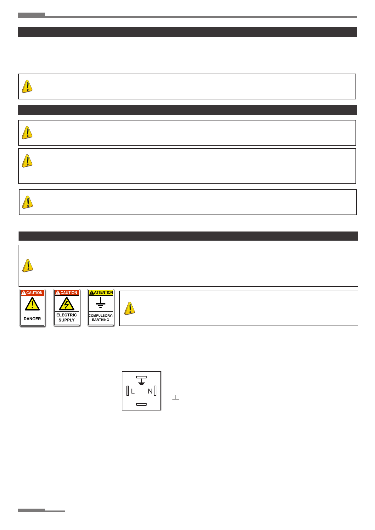
The appliance can be operated by specified voltage and frequency marked on its data board! The electrical connections and
groundings are prepared as per EN 60335 standard!
Electrical grounding specification: present appliance is equipped with three points grounding connection in the interests of your
protection!
It needed to ensure the sufficient quantity of combustion air if the appliance is installed without outside air supply!
Keep away the device from the following strong effects: wind, high pressure water jet, rain or dropping water!
The appliance must not be used in the open air!
The application of device is STRICTLY PROHIBITED in such rooms, which are used for sleep or continuous stay!
Keep away the flammable materials from the appliance and its near environment as follows: fuels,thinner or other flammable fluids
and vapours!
In the interests of avoiding of dust explosion do not used the device in such rooms where the degree of dust concentration is high
if the device is installed without outside air supply!
Before starting of appliance in every case check it in order to detect the possible damages! Never use damaged equipment!
In case of propane-gas operation never install the device in basement or from that lower being rooms! The propane-gas is heavier
specific gravity than the air for this reason in case of possible escaping it will spread towards the lower located rooms!
Only use that kind of flexible gas pipe and pressure regulator, which is offered for the appliance by the manufacturer!
Before every starting of heater appliance check the condition of connecting gas hose and if it is particularly worn or damaged in
that case exchange it for a new one specified by manufacturer!
Preserve the equipment in genuine condition, do not leave it to grow old!
Do not use seriously aged equipment any longer!
Fix the appliance on such stable surface, which during operation despite warming of appliance preserves its stability!
If the appliance is put out of use in every case it must be cut off the current and gas!
Never block the air supply and exhaust pipes!
Keep away the children and animals from the equipment!
Never service/mend such devices, which are hot and during operation or electrical charged!
Never mount such air duct unit on front or back side of device, which is not approved by manufacturer!
Use exclusively genuine-approved by manufacturer-spare parts,do not install similar quality spare parts for substitution! These kind
of substitute parts can cause serious damages concerning the operation of appliance!
Making up of gas and electrical connection in compliance with the specifications (it is proposed to connect with the local Building
Supervisory Authority or Fire-service),
Installation of equipment in accordance with the definitions of this manual,
Installation according to the fire prevention rules,
Supply of the necessary materials/components for installation(which are not belong to appliance),
Planing of air duct systems (ventilation/connections)
Service execution,
Placing the copy of present manual at owner’s disposal,
Assuring of sufficient air circulation around the appliance,
Determination and assuring of needed air for burning, ventilation and blowing in according to the specifications�
The appliance is equipped with data board, which is placed on outside of device’s door� On this data board there are information con-
cerning the type of device, gas type, electrical connection and flue types�
1. picture: Data board
2.
Installer’s responsibilities
Data board
8,6 mbar
Manufacturer
Type
Nominal input:
18 kW
Naturalgas
Pconnecting max.:
20-2776-29659
Series number:
HR
Targeted country:
Category:
II2H3B/P
20 mbar
Gas type:
Electrical protection:
Electrical connection:
Max.current entry:
IP21
AC 230V 50Hz
Pconnecting nom.:
Flue system:
Dat e/place of producti on
15.02.2021
60 mbar
Jet pressure:
NOx
4
Zenit-18/L
PAKOLE Trade Kft.
8000 Székesfehérvár,
Börgöndi út 8-10.
PIN:
0,45 A
1008 CT 3271
2806 20
B23, B53, C13, C33, C53, C83

ZENIT TYPE TUBE RADIANT HEATER User’s Manual
5
air!
The manufacturer can not assume responsibility for fault of equipment in case the installation is not happened according to the above�
This responsibility concerns completely the installer� In order to avoid such eventualities, if it is not certain to fit to the building or activity,
ask our colleague for help
Both the owner and the installer have to identify every possible material, which can be present in the building (inflammable materials,corrosive
materials, halo hydrocarbons etc�), and with knowledge of these materials must be planed the heater system!
Every appliance installation must be satisfied the valid laws and standards� These laws refer to the gas and electrical installation respec-
tively the ventilation (special specifications refer to park houses, aircraft hangars etc)�
Installation must be carried out always strictly complying with the current standards of the country
where the appliance is going to be used and following, of course, the instructions given by the
producer�
The installation and maintenance operations of the unit can be carried out by qualified and trained
personnel only�
Qualified service engineers are those having specific technical experience and/or valid license in the field of heating and cooling installa-
tion for home and industry� In any case, call the Manufacturer office or the closest dealer (www�pakole�com) and ask for further informa-
tions�
According to the installation project, install the electric power lines�
Always make sure that the unit and all its electrical parts have been cor-
rectly earthed prior starting up the unit�
If you have to disassemble the unit, use special protective gloves�
Beware of sharp edges inside the unit!
Beware of roof corners of outdoor units!
Keep suction grids always clear!
Before cleaning or maintaining the unit, make sure that all electrical parts
have been switched off, the appliance gas supply chain is closed and wait
until the appliance cools down� In particular, make sure that the fan is off
and cannot be inadvertently started prior to opening inspection panels�
Fans can reach a speed of 1000 rpm� Do not insert any object nor hands
in the electric fan�
We recommend to install a safety switch which can be easily reached to
cut off the current, near the unit� Before any cleaning and servicing opera-
tion, cut off the power line to the unit�
Before opening the unit, make sure that all electrical parts have been
switched off� In particular, make sure that the fan is off and cannot be inad-
vertently started prior to opening inspection panels�
CHECK THE EARTHING !!
This unit is designed to be used for heating purposes only� Any different use is not allowed as it may be dangerous�
Should the unit work in a house where disabled people and/or children live, it must be placed safely away from their
reach� Always make sure that the access door to the inside control board stay locked�
An incorrect installation can cause damages to people, animals and property� In case of erroneous installation, the manu-
facturer cannot be held responsible for such damages�
•
Corrosive materials
Standards and laws
Safety signs
Safe usage
CAUTION
DANGER
CAUTION
ELECTRIC
SUPPLY
CAUTION
DANGEROUS
OPERATION
CAUTION
HIGH
TEMPERATURE
CAUTION
DISCONNECT
POWER LINE
ATTENTION
COMPULSORY:
EARTHING
ATTENTION
THE USAGE OF
MOVING EQUIPMENT
IS COMPULSORY
ATTENTION
COMPULSORY:
USE PROTECTIVE
GLOVES
ATTENTION
ONLY
QUALIFIED
PERSON
ATTENTION
FORBIDDEN !
CAUTION
DANGER
ATTENTION
ONLY
QUALIFIED
PERSON
CAUTION
DANGER
CAUTION
DANGER
CAUTION
DANGER
CAUTION
DANGER
CAUTION
DANGER
CAUTION
ELECTRIC
SUPPLY
CAUTION
ELECTRIC
SUPPLY
ATTENTION
COMPULSORY:
EARTHING
ATTENTION
COMPULSORY:
EARTHING
ATTENTION
ONLY
QUALIFIED
PERSON
ATTENTION
ONLY
QUALIFIED
PERSON
ATTENTION
COMPULSORY:
USE PROTECTIVE
GLOVES
CAUTION
DANGEROUS
OPERATION
ATTENTION
FORBIDDEN !
CAUTION
DISCONNECT
POWER LINE

ZENIT TYPE TUBE RADIANT HEATER User’s Manual
6
Never use the unit to support other equipment�
Never leave tools, spare parts, etc� inside the unit�
Make sure that all inspection panels are closed properly�
Do no expose the unit to inflammable gases�
In case of breakdown or failure: turn unit off, do not try to repair it on your own, call operator�
If you are going to leave the heater switched off for a long time, first make sure that in no way this could cause harm
to anyone in any way�
The appliance operates on the basis of radiant heating� The combustion products of burned up gas and air mixture flow through the thin-
walled browned straight or „U”-form pipes and warm it up� The aluminium reflector shields, which have the best reflecting ability radiant
the made heat to the heated area�
Operation principle: the centrifugal fan of tube radiant heater draws in the combustion-air and pushes out the combustion products -
made by burning up of gas and air mixture at the „pusher” side of fan in the burner head – through the flue system into the open air�
The variety-list of appliances to be found in the enclosure 1.
The heating and consumption values to be found in the enclosure 2. as per appliance and gas types�
The supply of combustion air of appliance can be realized in two ways:
painting workshops and workshops, which are using explosive or corrosive materials etc�
The delivery must be made according to the following:
The package must be carefully secured in the loading space�
The package must be transferred in a closed space (always keep packing parts away environmental impacts)�
The unit has a special safety packing for transport and delivery which must be kept in good conditions till the unit is positioned
on the installation place�
Make sure that the unit has all its parts, as specified in the order�
Check if there are any damages and if the unit abbreviation is the same as the one of the ordered model�
Every unit is factory tested before shipment, therefore, if there are damages, report them immediately to the carrier�
Transporting, unloading and moving is a process which must be made carefully to avoid any kind of damages� Try not to use the unit’s
components as hand holds� When lifting, bear in mind that the centre of gravity of the unit may be off-centre�
The appliances will be delivered in card board box� The unpacking process of the appliance:
unload the burner the tubes and the accessories from the card board box�
do not remove the protection cap from the burners gas connection or from the gas joining set (optional) until you do not
connect it to the pipe line.
Check the unit and its accessories for any damages which could be arise during the transportation�
if there are any damages found, report them immediately to the manufacturer or your closest dealer�
There is an envelope inside the unit containing the Instructions for Installation and Servicing, User’s Guide use and Guarantee and
services and the warranty documents�
3.
4.
ATTENTION
THE USAGE OF
MOVING EQUIPMENT
IS COMPULSORY
ATTENTION
ONLY
QUALIFIED
PERSON
ATTENTION
FORBIDDEN !
CAUTION
DANGER
ATTENTION
FORBIDDEN !
ATTENTION
ONLY
QUALIFIED
PERSON

ZENIT TYPE TUBE RADIANT HEATER User’s Manual
7
Components of „I” -form tube radiant heater
Components of „U”-form tube radiant heater
L-form tube radiant heater appliance: see fig. 2
For 3 m (total length) long appliances only 2 hangers should be placed 1800 mm apart, and 700 mm far from the beginning of burner tube�
During assembling of straight system the installation of 1 pc 90° elbow is allowed but it must be placed minimum 6m far from the burner�
„U”-form tube radiant heater appliance: see fig. 3
At the „U”-pipe appliance in case of non side-wall-placing execution – which is not suspended at an angle – the burner head can be in-
stalled into optional side of „U” pipe, just taking it into consideration that the turbulant unit be at the end of last tube before flue gas outlet�
Combi hanger
Burner
Reflector hanger
Tube connection
Reflector Connection element
2. picture: “I”-form appliance
Combi hanger
Burner
Reflector hanger
Tube connection
U element
3. picture: “U”- form appliance
5.

ZENIT TYPE TUBE RADIANT HEATER User’s Manual
8
• SOLELY INTERIOR installation is possible�
• The installation must comply with the valid standards�
• For the sake of appropriate efficiency the position and the high of installation has to be carefully defined�
• The appliance has to be placed in that way that its every part be accessible�
Appliance installation
Gas connection
ELECTRICAL CONNECTING SPECIFICATIONS:
The appliance/burner head can be connected to the mains by safety electrical connector (Fig�13) located on the fan
side of appliance head�
The appliance must be operated under dry circumstances�
At electrical installation of appliance the relevant standard must be considered�
The mains connection can be executed by grounded plug or fixed properly installed phase-null wires�
The appliance is phase-sensitive for this reason the connection always must be according to the Fig�13�
Fort he sake of suitable detachability of appliance from the electrical supply, double-pole – phase / null switching off – detaching main-
switch must be installed�
Electrical wiring: 3 x 0,75 MT cable
Fuse: 2A dissolving fuse
Before change of dissolving fuse by disconnecting of Hirschmann plug the appliance must be detached from electrical supply�
The combustion–air supply centrifugal fan is fixed to the appliance/burner head, the automatic burner control is located in the burner
head in this way the electrical supply has to be installed just into the appliance head�
Electrical connection
15.picture: Electrical connection
CAUTION
DANGER
CAUTION
ELECTRIC
SUPPLY
ATTENTION
COMPULSORY:
EARTHING
L - phase
N - null
- ground

ZENIT TYPE TUBE RADIANT HEATER User’s Manual
9
Optional thermostats, regulators
24.picture: Temperature controller
FP-1D 2-point regulation thermostat
FP-3D
3-point regulation thermostat
with weekly hour programming
Temperature sensor
FP-4D
2-point regulation thermostat
with weekly hour programming
FP-MOD
Modulated regulation thermostat
with weekly hour programming
Recommended temperature controllers for the appliance (these can be purchased at the appliance manufacturer)
The ZENIT tube radiant heater can be controlled manually or automatically�
The electrical supply of appliance is interrupted manually, based on sense of temperature: Centrally, at each heating zones by a common
box Individually, at each appliances separately�
Automatic control of temperature is accomplished by a temperature regulator, which switch on and off the appliance automatically trough
the electrical input of its according to the requested heat sensation� This temperature regulator – temperature regulator + temperature
sensor - can be programmable or simple one� The automatic control can be:
Traditional (2-point) regulation with Honeywell S4965R or SIT 579 DBC electronics
3-point regulation (on ; 50/60% ; off ) with SIT 579 DBC electronics and 840SIGMA solenoid valve
Modulation with SIT 579 DBC electronics and 845SIGMA solenoid valve
Control of appliance
Principle: during the operation of appliance 3 modes are possible, 100% or 60% of power or off mode (standby position)�
The regulation made by thermostat, which senses the temperature changing and turns on the 100%, 60% power or turns off the appli-
ance� The appliance always starts the operation with 100% power and when the sensed temperature reaches the adjusted temperature
on the thermostat, then it automatically reduces the power to the pre-adjusted minimum 60%� The heating goes on with this power, and if
this power is enough for keeping of temperature then it stay in this mode� If this input is still big for the heating, then the thermostat turns
off the appliance� If the temperature is decreasing (e�g� opened door) then the thermostat resets the power of appliance to the 100% This
kind of regulation makes it possible that the needed sensation of temperature be continuously served during an economical operation�
That the reduced input can be 50% or 60%,it depend on the length of pipes and the temperature of exiting combustion products in every
case. Type of temperature controller: so called 3-point control thermostat.
There are three states according to operation of appliance: Out off operation, operation between performance of 100% and 50% or
maximum (100%) performance� Is the control of appliance by the thermostat which can sense the room temperature� The thermostat can
control the black tube radiant heater according to needed set up temperature� (The detailed manual of thermostat can be found supplied
with thermostat) When the thermostat send a sign than the heater starts with maximum performance (this time is minimum 30 sec) The
appliance keeps this performance till the difference is between temperature of room and the set temperature is 3°C degrees, than the
control begin degrease the performance of appliance without any stage continuously to 50% of performance where the control keeps it
during this time till the temperature reaches the set temperature� After these the thermostat switch off the appliance� Type of thermostat
can be: only use capable type of control which can handle the modulation control�(e�g�: FP-MOD type by Pakole Trade Kft�)
25.picture: Explanation of heat-radiated area
Heat-radiated area

ZENIT TYPE TUBE RADIANT HEATER User’s Manual
10
From flammable materials it is obligatory to keep SAFETY OF OPERATION and FIRE PREVENTION distances!
Protective distances
26.picture: Fire-protection distances
C
1
E
Power Protective distances
A B C C1 E
12–14 kW 0�12 m 1�1 m 0�3 m 0�8 m 0�8 m
16–20 kW 0�12 m 1�3 m 0�6 m 0�9 m 0�8 m
22–28 kW 0�15 m 1�5 m 0�8 m 1�0 m 1�0 m
30–36 kW 0�15 m 1�6 m 0�8 m 1�0 m 1�0 m
38–44 kW 0�18 m 1�6 m 1�0 m 1�0 m 1�0 m
46–52 kW 0�18 m 1�8 m 1�0 m 1�2 m 1�2 m
54–58 kW 0�18 m 2�0 m 1�2 m 1�5 m 1�2 m
ZENIT Pipe
position
Minimum installation height for input power
10 kW 15 kW 20 kW 25 kW 30 kW 35 kW 40 kW 45 kW 50 kW 55 kW 60 kW
„U”
form
Horizontal 3�4 m 3�7 m 4�0 m 4�2 m 4�4 m 4�6 m 4�9 m 5�2 m 5�4 m 5�7 m 5�9 m
30° 3�0 m 3�2 m 3�4 m 3�7 m 3�9 m 4�1 m 4�3 m 4�6 m 4�8 m 5�0 m 5�3 m
„L” form Horizontal 3�2 m 3�5 m 3�7 m 4�0 m 4�2 m 4�5 m 4�7 m 5�0 m 5�2 m 5�4 m 5�6 m
30° 2�7 m 3�0 m 3�2 m 3�4 m 3�6 m 3�9 m 4�1 m 4�3 m 4�5 m 4�7 m 4�9 m
28.picture Minimal ascent of installation

ZENIT TYPE TUBE RADIANT HEATER User’s Manual
11
After determining the number and exact position of appliances and hangers,you have to provide for hanging them at a minimum of
400 mm (hanging chains for example)� This is necessary, so it does not hinder the length change, which increases dueing thermal
expansion,hereby appliances does not deform� Install hangers under the roof structure, under buttresses or scaffolding among columns
or nerby wall�The suspension of appliances have to be executed by hanger located on the fan side of burner and combination brackets�
30. picture: Suspension possibilities
When placing the suspensions, the correct suspension of the burner must also be taken into account, be-
cause due to the incorrect suspension, during the thermal expansion, deformations can occur on the burner tube�
Do not suspend the burner vertically, but pull it slightly towards the burner using the chain�
It is recommended to use a chain tensioner for perfect suspension�
27 picture: Maximal angle of installation
min. 400 mm
min. 400 mm

ZENIT TYPE TUBE RADIANT HEATER User’s Manual
12
Combustion air may be drawn in from more spaces�
a) from inside (heated) space
b) from outside, in case outside combustion-air system is connected to the fan�
The combustion air must not drawn in from internal space in the following cases:
if the heated building is under lower pressure than the outside
if the atmosphere is contaminated with acid fumes, fluorocarbons, corrosive substances,dirt, oil, etc�,which can damage the
fan and pipe system
In this case the combustion air must be conducted to the device from the external space.
Tube length for combustion-air supply
6 meter with one elbow from 100 mm diameter tube�
15 m with two elbows from 150 mm diameter tube� More elbows can be used� One 90° elbow is correspond to 1 meter tube length
When two appliances are controlled by one thermostat in that case a common combustion-air supply can be used� The common duct of
two appliance must be Ø 150 mm and should not exceed 15 m in length� Maximum two 90° elbows may be used�
Combustion-air supply
Exhaust arrangements of combustion products
Flue channel to the outside of building at each appliance
Common flue channel for two appliances
•
Flue pipe is not allowed to have a low point, it must be made of Ø100 mm stainless steel or aluminium. The minimum ascent of flue pip-
ingmustbe2cm/m≈1°
Type of the exhaust system:
The length of exhaust system:
The length of the exhaust system depend on the allowed maximal length and the used length of the appliance� The total length of exhaust
system can be the difference of allowed maximum length (m) as per types (ZENIT-12…58) and the used length – at the installation – plus
6 m�
L :Total length of exhaust system
LMAX :The allowed maximal length of appliance (it is defined as per types)
Lused :The used length of appliance (at the installation)
L = LMAX - Lused + 6 [m]
The total length of exhaust system can be expandable with 1 piece 90° elbow without any correction.
31.picture: Outside combustion-air supply
Flexible tube
ZENIT-type tube radiant heater
Inhale opening
End plate
6.

ZENIT TYPE TUBE RADIANT HEATER User’s Manual
13
Before putting operation of appliance the leak-proof/pressure test of gas supply system must be fulfilled.
Clean duct system of gas supply from any contamination�
Check the presence and cleanness of gas filter located before the appliance
Check the presence and suitability of pressure regulator located centrally or before every appliance�( the pressure regulator
is needed if the gas supply pressure is higher than 60 mbar,in this way the capacity of pressure regulator can be max� 60
mbar)
Make sure of protective ground of appliance�
Check the proper electrical connection of temperature regulator�
Open the gas supply valve�
Check the gas pressure on the inlet side of solenoid valve�(the maximum allowed pressure is 60 mbar)�
Connect the mains voltage to the appliance (by temperature regulator or central stage main-switch)�
Check the outlet pressure of solenoid valve,whether the set up pressure – nozzle pressure – is suitable for the type of gas�
At Natural gas – depending on output: 8�6, 9�5 or 10 mbar
At „S” gas – depending on output: 8�6, 10, 11, 11�8, or 12�5 mbar
At Propane and butane: 24�9 mbar
7.
Following the switched on voltage the fan operates continuously assuring the 30 seconds pre-purge time� This time period ensures the
three times air change of combustion volume in case of biggest appliance’s power�
When the pressure is suitable - after 30 seconds – the sparking happens and the solenoid valve opens in this way the gas catches fire�
In case during 5 seconds sparking(ignition) the continuous flame shape is stabilized, - and stable electrical signal is come back from the
electrode – the appliance operates and the green control lamp is lighting� During operation of appliance its automatic burner control con-
trols the condition of differential pressure switch and signals coming from the flame control continuously, and if the position of differential
pressure switch is changed – it is switched over from work position to rest – or the signal from the ionization flame control is interrupted
then it stops the gas supply of burner and the appliance gets into error position and red control lamp is lighting placed on the bottom side
of appliance�
If the flame control of burner automation does not register flame during the safety time than repeats the all ignition procedure
maximum two times. If in this time there is not registered flame then it stops the gas supply of burner and the appliance gets into error
position and red control lamp is lighting�
In case during burning process the pressure decreases under the permissible minimal
value on the positive side of air pressure(from the fan side),then automation prohibits:
- gas supply and fan stops
The appliance stands into error position and red control lamp is lighting�
Restart is possible after the switching off and on of mains voltage.
In case during burning process the pressure increases above the permissible maximum value on the negative side of air pressure switch
(from the burner tube side, eg� at combustion back),then it switches back to rest position and the automation prohibits�
- gas supply and fan stops
The appliance stands into error position and red control lamp is lighting�
Restart is possible after the switching off and on of mains voltage�
8.
Start, restart
Operation of automatic burner control (HONEYWELL S4965R)
41. picture: Input and output gas pressure cheking connections in case of
HONEYWELL solenoid valve
direction of gas flow
OUTPUT INPUT
direction of gas flow

ZENIT TYPE TUBE RADIANT HEATER User’s Manual
14
42.picture: Input and output gas pressure cheking connections in case of SIT solenoid valve
Following the switched on voltage the fan operates continuously assuring the 30 seconds prepurge time� This time period ensures the
three times air change of combustion volume in case of biggest appliance’s power�
When the pressure is suitable - after 30 seconds – the sparking happens and the solenoid valve opens in this way the gas catches fire�
gas flow
direction
gas flow
direction
1� On-Off solenoid valve EV1
2� On- Off solenoid valve EV2
3� Inlet pressure test point
4� Outlet pressure test point
5� Connection for pressure regulator / combustion chamber compensation
6� Servo pressure regulator
The flame sensor is self-monitoring and only performs an intervention on the burner it controls, insensitive to other environmental effects
(eg�: external heat, light)
In case during 5 seconds sparking (ignition) the continuous flame shape is stabilized, - and stable electrical signal is come back from the
electrode – the appliance operates and the green control lamp is lighting� During operation of appliance its automatic burner control con-
trols the condition of differential pressure switch and signals coming from the flame control continuously, and if the position of differential
pressure switch is changed – it is switched over from work position to rest – or the signal from the ionization flame control is interrupted
then it stops the gas supply of burner� The fan continues to rotate, none of control lamps is lighting�
In case during the burning process the pressure decrease under the permissible minimal value ont he positive side of air pressure (from
the fan side), then automation prohibits:
- gas supply and fan stops
The fan continues to rotate, none of control lamps is lighting�
In case during burning process the pressure increases above the permissible maximum value on the negative side of air pressure switch
(from the burner tube side, eg� at combustion back),then it switches back to rest position and the automation prohibits�
- gas supply and fan stops
The appliance stands into error position and red control lamp is lighting�
Restart is possible after the switching off and on of mains voltage�
Operation of automatic burner control (SIT 579 DBC)

ZENIT TYPE TUBE RADIANT HEATER User’s Manual
15
The ZENIT-type tube radiant heater appliance apart from the supervision and cleaning of radiant tubes (see: Maintenance supervision by
the customer), do not need extra maintenances but to be able to preserve the SAFETY OPERATION and LONG LIFETIME of appliance
it is recommended to have yearly supervision done by qualified service department�
Maintenance supervisions by the customer
a) Supervision and cleaning of heat radiant tubes�
Clean the external surface of tubes from any dust by a brush and make sure that there is not any burnout or warping�
b) Check connection and sealing of burner tube and heat radiant tubes by a survey� In case there is lack of sealing, colouring
shows it�
c) Check the condition of reflectors if necessary clean them� Clean them by a soft cloth or diluted detergent�
d) Check the suspensions, make sure that the load is distributed smoothly at all mountings� You can check it moving each hanger a
little�
e) Cleaning the flue pipes�
Remove the barrier by the combustion product and reset the original condition
Restart the device by interrupting and resetting the power supply�
It is advisable to make a maintenance contract for the proper maintenance or call our qualified service department for regular mainte-
nance�
Carry out starting test and check the regular operation of appliance�
Checking of the regular operation�
Two kind of supervision should be fulfilled:
a) Switch on the appliance, let it operate some minutes, then turn off the gas valve� The burner stops the operation� Wait for 6-8
seconds,then turn on the gas valve once more, the appliance starts the operation again��
b) Let it operate some minutes� Then take down the exhaust end of heat radiant tubes and close the vent opening� The differential
pressure switch switches over to OFF position from ON� The automation closes the solenoid valve and the appliance stops and
red control lamp is lighting�
Remove the closing of tube and reset the original condition� Start the appliance again by interruption then reconnecting of
mains voltage�
Maintenances
Check at the beginning of season
9.

ZENIT TYPE TUBE RADIANT HEATER User’s Manual
16
Structural elements which are responsible for the operation
solenoid valve
control box
air pressure switch
fan
Gas change
-
a) Supervision of nozzle pressure (at the outlet of solenoid valve)
b) Checking the condition of pressure regulator�
c) Cleaning of gas filter�
d) Checking the condition of differential pressure switch�
e) Checking the presence of protective ground�
f) Supervision of electrical connection�
g) Supervision of combustion air fan�
Check, whether the wheel of fan is able to revolve free and remove the possible contaminations from revolving blades�
Maintenance supervisions by a qualified service department
All kinds of interventions for which disassembly of appliance is necessary:
The following control lamps located on the bottom side of appliance (burner head) indicates the mode :
10.

ZENIT TYPE TUBE RADIANT HEATER User’s Manual
17
The radiant tube length included the length of the reduction element (L-form) and the length of the U-element (U-form)
The whole appliance length is calculated with the length of radiant tube and the length of burner (0,6 meter)�
The L-form tube radiant heater is linear, and the U-form tube radiant heater is U-form�
The complete weight includes the burner head, burner and radiator tubes, canopy, canopy holders and S-hooks� It does not include the
suspension chain and other accessories needed for hanging�
11.
Enclosure 1.: Variety-list of ZENIT-type tube radiant heaters, length, weight
Radiant tube type
Appliance length (m)
L6 U3 L9 U4,5 L12 U6 L15 U7,5 L18 U9 L21 U10,5
6�65 3�86 9�57 5�29 12�50 6�79 15�42 8�21 18�35 9�71 21�27 11�14
Full weight (kg) 41�1 44�7 54�9 57�7 68�7 72�7 82�5 85�4 96�3 100�5 110�1 113�1
ZENIT-12 x x - - - - - - - - - -
ZENIT-14 xx----------
ZENIT-16 xxxx--------
ZENIT-18 xxxx--------
ZENIT-20 xxxx--------
ZENIT-22 - - x x x x - - - - - -
ZENIT-24 - - x x x x - - - - - -
ZENIT-26 - - x x x x - - - - - -
ZENIT-28 - - x x x x x x - - - -
ZENIT-30 - - - - x x x x - - - -
ZENIT-32 - - - - x x x x - - - -
ZENIT-34 - - - - x x x x x x - -
ZENIT-36 - - - - x x x x x x - -
ZENIT-38 - - - - - - x x x x x x
ZENIT-40 - - - - - - x x x x x x
ZENIT-42 - - - - - - x x x x x x
ZENIT-44 - - - - - - x x x x x x
ZENIT-46 - - - - - - x x x x x x
ZENIT-48 --------xxxx
ZENIT-50 --------xxxx
ZENIT-52 ----------xx
ZENIT-54 ----------xx
ZENIT-56 ----------xx
ZENIT-58 ----------xx

ZENIT TYPE TUBE RADIANT HEATER User’s Manual
18
Enclosure 2.: Heating and consumption values of ZENIT-type tube radiant heaters
Type Input power Gas consumption
[m3/h] [kg/h]
[kW] Natural gas Propane-Butane Propane
ZENIT-12 12�6 1�32 1�05 1�02
ZENIT-14 14�1 1�48 1�18 1�14
ZENIT-16 15�8 1�66 1�32 1�28
ZENIT-18 18�3 1�92 1�53 1�48
ZENIT-20 19�8 2�08 1�65 1�6
ZENIT-22 22�7 2�38 1�9 1�83
ZENIT-24 24�4 2�56 2�04 1�97
ZENIT-26 26�2 2�75 2�19 2�12
ZENIT-28 28�2 2�96 2�36 2�28
ZENIT-30 30�6 3�21 2�56 2�47
ZENIT-32 31�9 3�35 2�67 2�58
ZENIT-34 34�6 3�63 2�89 2�8
ZENIT-36 36�5 3�83 3�05 2�95
ZENIT-38 38�1 4�00 3�18 3�08
ZENIT-40 39�6 4�16 3�31 3�2
ZENIT-42 42�8 4�49 3�58 3�46
ZENIT-44 44�6 4�68 3�73 3�61
ZENIT-46 46 4�83 3�84 3�72
ZENIT-48 48�1 5�05 4�02 3�89
ZENIT-50 49�8 5�23 4�16 4�03
ZENIT-52 51�9 5�45 4�34 4�2
ZENIT-54 54�1 5�68 4�52 4�37
ZENIT-56 55�9 5�87 4�67 4�52
ZENIT-58 58�3 6�12 4�87 4�71

ZENIT TYPE TUBE RADIANT HEATER User’s Manual
19
Type Input power Gas consumption
[m3/h] [kg/h]
[kW] Natural gas Propane-Butane Propane
ZENIT-12 12�6���8�9 1�32���0�93 1�05���0�74 1�02���0�72
ZENIT-14 14�1���9�9 1�48���1�04 1�18���0�83 1�14���0�8
ZENIT-16 15�8���10�6 1�66���1�11 1�32���0�89 1�28���0�86
ZENIT-18 18�3���11�6 1�92���1�22 1�53���0�97 1�48���0�94
ZENIT-20 19�8���12�6 2�08���1�32 1�65���1�05 1�6���1�02
ZENIT-22 22�7���12�8 2�38���1�34 1�9���1�07 1�83���1�03
ZENIT-24 24�4���14�8 2�56���1�55 2�04���1�24 1�97���1�2
ZENIT-26 26�2���15�9 2�75���1�67 2�19���1�33 2�12���1�29
ZENIT-28 28�2���16�3 2�96���1�71 2�36���1�36 2�28���1�32
ZENIT-30 30�6���17�1 3�21���1�8 2�56���1�43 2�47���1�38
ZENIT-32 31�9���20�1 3�35���2�11 2�67���1�68 2�58���1�62
ZENIT-34 34�6���21�1 3�63���2�22 2�89���1�76 2�8���1�71
ZENIT-36 36�5���22�7 3�83���2�38 3�05���1�9 2�95���1�83
ZENIT-38 38�1���23�2 4���2�44 3�18���1�94 3�08���1�88
ZENIT-40 39�6���24�1 4�16���2�53 3�31���2�01 3�2���1�95
ZENIT-42 42�8���25�1 4�49���2�64 3�58���2�1 3�46���2�03
ZENIT-44 44�6���27�6 4�68���2�9 3�73���2�31 3�61���2�23
ZENIT-46 46���28�7 4�83���3�01 3�84���2�4 3�72���2�32
ZENIT-48 48�1���31�2 5�05���3�28 4�02���2�61 3�89���2�52
ZENIT-50 49�8���34�6 5�23���3�63 4�16���2�89 4�03���2�8
ZENIT-52 51�9���35�2 5�45���3�7 4�34���2�94 4�2���2�85
ZENIT-54 54�1���36�1 5�68���3�79 4�52���3�02 4�37���2�92
ZENIT-56 55�9���37�5 5�87���3�94 4�67���3�13 4�52���3�03
ZENIT-58 58�3���38�1 6�12���4 4�87���3�18 4�71���3�08

ZENIT TYPE TUBE RADIANT HEATER User’s Manual
20
Model: ZENIT 6m „L” Gas-fired overhead radiant tube heaters Linear shape
Type of heating: Radiant tube
Fuel: Gaseous Type of fuel: Natural Gas Propane Butane Propane-Butane
Space heating emission NOx138.8 mg/kWhinput (GCV)
Characteristics when operating with the preferred fuel only
Item Symbol Value Unit Item Symbol Value Unit
Heat output Useful efficiency - GCV
Nominal
heat output Pnom 21.9 kW Useful efficiency at nominal
heat output hth.nom 82.41 %
Minimum
heat output Pmin 14.0 kW Useful efficiency at minimum
heat output hth.min 81.19 %
Minimum heat
output - as percentage
of nominal heat output
-- 63.8 %
Radiant factor Envelop losses
Radiant factor at
nominal
heat output
RFnom 50.7 % Envelope insulation class U 0.0 W/m2K
Radiant factor at
minimum
heat output
RFmin 48.6 % Envelope loss factor Fenv 0.0 %
Regulation (EU) 2015/1188 Heat generator to be installed
outside the heated area Yes No Possible
Auxiliary electricity consumption Heat output control type
At Nominal heat
output elmax 0.095 kW - Single stage (ON-OFF) Yes No
At minimum heat
output elmin 0.061 kW - Two stage (100%-60%-OFF) Yes No
In standby
mode elsb 0.0 kW - Modulated Yes No
Permanent pilot flame power requirement
Pilot flame power
requirement (if
applicable)
Ppilot 0.0 kW
Contact
details PAKOLE Trade Kft. H-8000, Székesfehérvár. Börgöndi út. 8-10
Table of contents
Other Pakole Heater manuals

Pakole
Pakole LH-30 User manual

Pakole
Pakole ACR 100W Installation guide

Pakole
Pakole GTV-E-20A User manual

Pakole
Pakole AIRFUSOR AFR-0 User manual

Pakole
Pakole ZENIT 80+ Series User guide

Pakole
Pakole GHI-11 User manual

Pakole
Pakole ACR 1000W Installation guide

Pakole
Pakole ACR PRO Installation guide

Pakole
Pakole GTV-E-20A User manual
Popular Heater manuals by other brands

STIEBEL ELTRON
STIEBEL ELTRON CNS 50 Operating and installation instructions

Inforesight
Inforesight Solaira Cosy XL Double Series Reference manual

STIEBEL ELTRON
STIEBEL ELTRON CNS 50 S Operation and installation

Herschel
Herschel Select XLS Series manual

iGenix
iGenix IG9101 Instructions for use

GDC Group
GDC Group Brazilia F 5 Installation and owner's guide