NOTE:- ØEquipment that fails inspection in any way must immediately be
removed from use, or repaired by an entity approved by the
ØWorkplace conditions, including, but not limited to, ame, manufacturer.
corrosive chemicals, electrical shock, sharp objects,
machinery, abrasive substances, weather conditions, and ØNo on-site repair of equipment unless explicitly permitted by the
uneven surfaces, must be assessed by a Competent Person manufacturer.
before fall protection equipment is selected.
ØEquipment subjected to forces of fall arrest must immediately
ØThe analysis of the workplace must anticipate where workers be removed from use. Snap hooks, karabiners, and other
will be performing their duties, the routes they will take to reach connectors must be selected and applied in a compatible
their work, and the potential and existing fall hazards they may fashion. All risk of disengagement must be eliminated. All snap
be exposed to. Fall protection equipment must be chosen by a hooks and karabiners must be self-locking and self-closing, and
Competent Person. Selections must account for all potential must never be connected to each other.
hazardous workplace conditions. All fall protection equipment
should be purchased new and in an unused condition. ØAge, tness, and health conditions can seriously affect the
worker should a fall occur. Consult a doctor if there is any
ØFall protection systems must be selected and installed under reason to doubt a user's ability to withstand and safely absorb
the supervision of a Competent Person, and used in a fall arrest forces or perform set-up of equipment.
compliant manner.
ØPregnant women and minors must not use this equipment.
ØFall protection systems must be designed in a manner Physical harm may still occur even if fall safety equipment
compliant with all federal, state, and safety regulations. functions correctly. Sustained post-fall suspension may result in
serious injury or death. Use trauma relief straps to reduce the
ØForces applied to anchors must be calculated by a Competent effects of suspension trauma. Allowable individual worker
Person. weight limit (including all equipment), unless explicitly stated
otherwise, is 40-100 kgs..
ØHarnesses and connectors selected must be compliant with
manufacturer's instructions, and must be of compatible size MAINTENANCE, CLEANING, AND STORAGE
and conguration.
ØRepairs to C0850 can only be made competent person or
ØA pre-planned rescue procedure in the case of a fall is required. an entity authorized by manufacturer. If a C0850 fails
The rescue plan must be project specic. The rescue plan must inspection in any way, immediately remove it from service, and
allow for employees to rescue themselves, or provide an contact manufacturer to inquire about its return or repair.
alternative means for their prompt rescue.
ØCleaning after use is important for maintaining the safety and
ØStore rescue equipment in an easily accessible and clearly longevity of C0850.
marked area.
ØRemove all dirt, corrosives, and contaminants from C0850
ØTraining of Authorized Persons to correctly erect, disassemble, before and after each use. If C0850 cannot be cleaned with
inspect, maintain, store, and use equipment must be provided plain water, use mild soap and water, then rinse and wipe dry.
by a Competent Person. NEVER clean C0850 with corrosive substances.
ØTraining must include the ability to recognize fall hazards, ØWhen not in use, store equipment where it will not be affected by
minimize the likelihood of fall hazards, and the correct use of heat, light, excessive moisture, chemicals, or other degrading
personal fall arrest systems. elements.
ØNEVER use fall protection equipment of any kind to hang, lift, LIMITATIONS
support, or hoist tools or equipment, unless explicitly certied
for such use. Fall Clearance: There must be sufcient clearance below the
anchorage connector to arrest a fall before the user strikes the
ØMaintenance of equipment must be done according to ground or an obstruction. When calculating fall clearance, account
manufacturer's instructions. Equipment instructions must be for a MINIMUM 3'safety factor, deceleration distance, user height,
retained for reference. length of lanyard/SRL, and all other applicable factors.
ØPrior to EACH use, all equipment in a fall protection system Swing Falls: Prior to installation or use, make considerations for
must be inspected for any potential or existing deciencies that eliminating or minimizing all swing fall hazards. Swing fall occurs
may result in its failure or reduced functionality. IMMEDIATELY when the anchor is not directly above the location where a fall
remove equipment from service if any deciencies are found. occurs. Always work close to in line with anchor point as possible.
Swing falls signicantly increase the likelihood of serious injury or
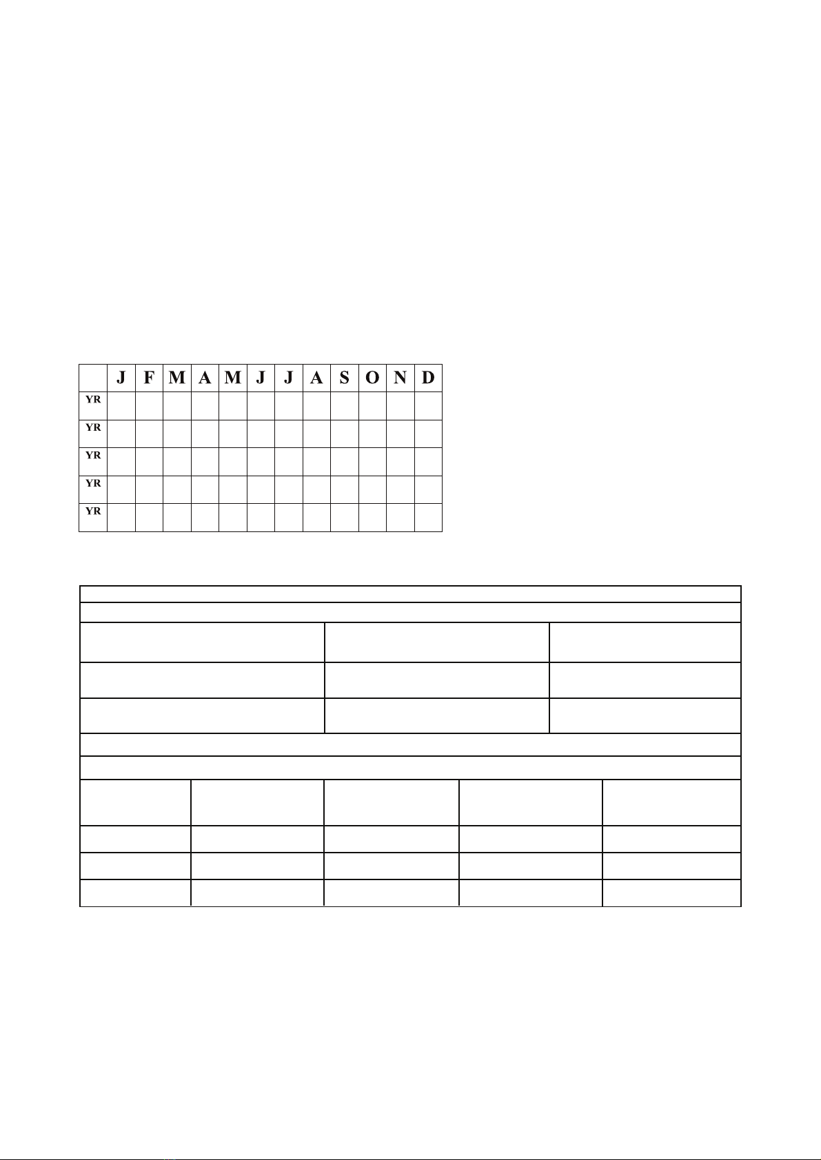
ØEquipment must be inspected by a Competent Person at least death in the event of a fall.
every six months. These inspections must be documented in
equipment instruction manual and on equipment inspection Compatibility: When making connections with C0850,
grid label. eliminate all possibility of roll-out. Roll-out occurs when interference
between a hook and the attachment point causes the compatible
ØEquipment must be inspected for defects, including, but not with C0850 by a competent person. All connector gates must be
limited to, the absence of required labels or self closing and self-locking and withstand minimum load of 3600
lbs.
markings, improper form/t/function, evidence of cracks, sharp
edges, deformation, corrosion, excessive heating, alteration, Vertical Lifeline Assembly (VLA): Specic Applications
excessive wear, fraying, knotting, abrasion, and absence of
parts.
Page 2 of 4
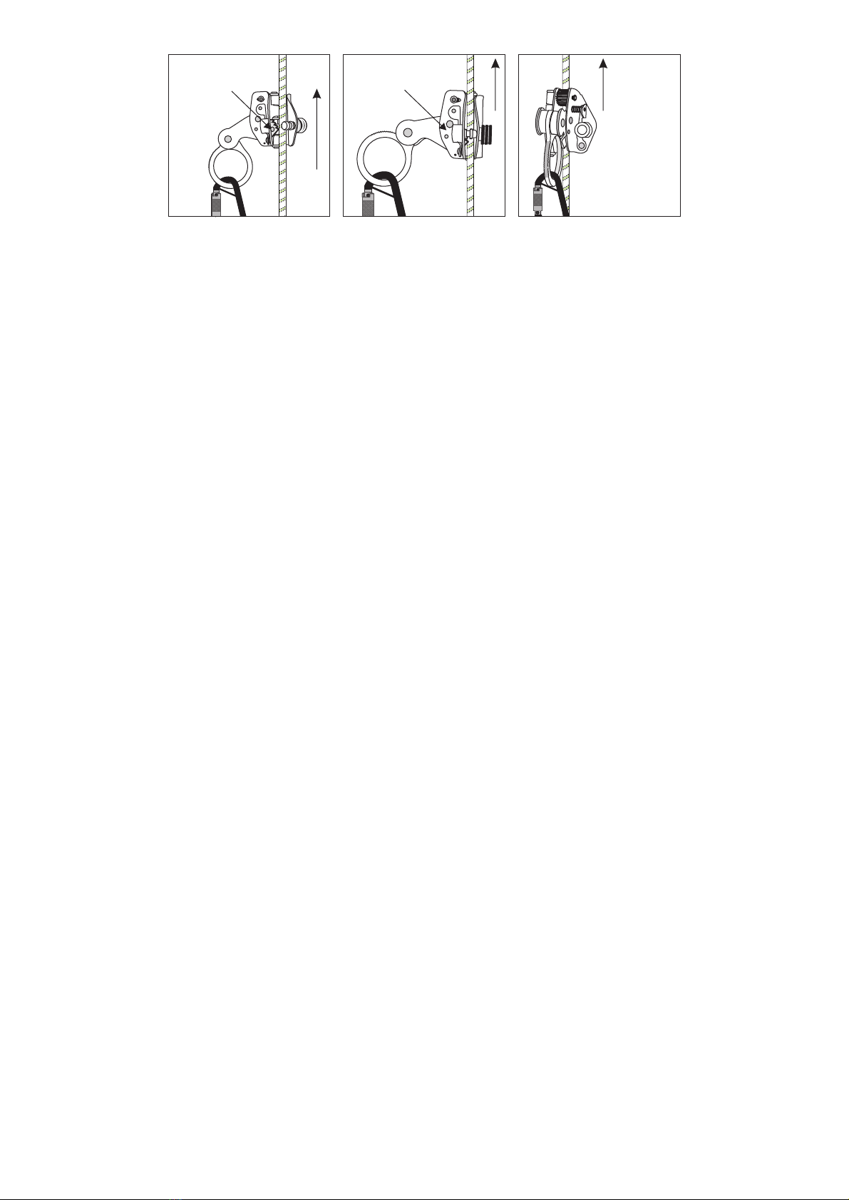
Direction of Usege
Close the flange and
Tigten the screw nut
Direction of Usege
Now, Connect The
System with your
Harness using a
karabiner and the
System is ready for
use
Now Install the Rope
Into The Fall Arrester
Direction of Usege