Palmgren 82088 User manual

operating anual & parts list 82088
COMBINATION GRINDER/SANDER
Read carefully and follow all safety rules and operating instructions before
first use of this product.
37115.00-0213

2
Palmgren Operating Manual & Parts List 82088
DESCRIPTION
Palmgren Combination rinder/Sander is used for grinding, debur-
ring, squaring, polishing and finishing metals, woods and plastics.
rinder/Sander has a totally enclosed, fan-cooled direct drive
motor. Belt housing swivels from vertical to horizontal for ginding
long workpieces. Features include fully adjustable tool rests on belt
and grinding wheel, quick release belt tension and tracking mech-
anism, OSHA compliant belt guard with dust port, spark guard and
safety eye shield for grinding wheel.
UNPACKING
Refer to Figure 1.
Check for shipping damage. If damage has occurred, a claim must
be filed with carrier. Check for completeness. Immediately report
missing parts to dealer.
To be certain the grinding wheels have not been damaged in ship-
ment, strike the edges slightly with a metal object. A ringing sound
indicates a good wheel, but a dull noise may signal a fracture.
WAR I G: If you suspect a wheel of being fractured, replace it
immediately. Fractured wheels may shatter, causing serious injury.
The grinder/sander comes assembled as one unit. Additional parts
which need to be fastened to grinder should be located and
accounted for before assembling.
A Stop rod with hex nut
B Belt rool rest bracket
C Belt tool rest
D 12mm Open end wrench
E 6mm Hex wrench
F rinder tool rest bracket
rinder tool rest
H 5⁄16 x 18 x 1” Knob (2)
I Upper eyeshield bracket
J Lower eyeshield bracket
K Eyeshield
L 1⁄4-20 x 1⁄2” Knob
M Spark guard
N 3⁄8-16 x 1⁄2” Knob (2)
Not shown:
3⁄8-16-3⁄4” Hex head bolt (2)
3⁄8” Flat washer (4)
5⁄16” Flat washer (2)
#10-24 x 3⁄8” Pan head screw (2)
SPECIFICATIO S
Belt size . . . . . . . . . . . . . . . . . . . . . . . . . . . . . . . . . . . . . . . . . . . .2 x 48”, 80 grit
Belt platen area . . . . . . . . . . . . . . . . . . . . . . . . . . . . . . . . . . . . . . .121
⁄4x 21
⁄2”
Belt speed . . . . . . . . . . . . . . . . . . . . . . . . . . . . . . . . . . . . . . . . . . . . . .4500 FPM
Belt dust port . . . . . . . . . . . . . . . . . . . . . . . . . . . . . . . . . . . . . . . . .2” diameter
Wheel size . . . . . . . . . . . . . . . . . . . . . . . . . . . . . . . . . . . . . . . . . . . .8 x 1 x 5⁄8”
Wheel type . . . . . . . . . . . . . . . . . . . . . . . . . . . . . . . .Aluminum oxide, A60P
Wheel speed . . . . . . . . . . . . . . . . . . . . . . . . . . . . . . . . . . . . . . . . . . .3450 RPM
Wheel dust port . . . . . . . . . . . . . . . . . . . . . . . . . . . . . . . . . . . . . . . .31⁄4” dia.
Dimensions (L x W x H) . . . . . . . . . . . . . . . . . . . . . . . . . . . . . . .21 x 14 x 26”
Dimensions-belt horizontal (L x W x H) . . . . . . . . . . . . . . .21 x 26 x 13”
Switch . . . . . . . . . . . . . . . . . . . . . . . . . . . . . . . . . . . . . . . . .DP, Locking rocker
Motor . . . . . . . . . . . . . . . . . .3⁄4 Hp, 115/230V, 7.0/3.5 AMPS, 3450 RPM
Weight . . . . . . . . . . . . . . . . . . . . . . . . . . . . . . . . . . . . . . . . . . . . . . . . . . . . .74 lbs
Shipping weight . . . . . . . . . . . . . . . . . . . . . . . . . . . . . . . . . . . . . . . . . . . .86 lbs
SAFETY RULES
WAR I G: For your own safety, read all of the instructions and
precautions before operating tool.
CAUTIO : Always follow proper operating procedures as defined in
this manual even if you are familiar with use of this or similar tools.
Remember that being careless for even a fraction of a second can
result in severe personal injury.
WAR I G: Some dust created by power sanding, sawing, grind-
ing, drilling and other construction activities contains chemicals
known to cause cancer, birth defects or other reproductive harm.
Some examples of these chemicals are:
•Lead from lead-based paints.
•Crystalline silica from bricks and cement and other masonry
products.
•Arsenic and chromium from chemically-treated lumber.
Your risk from these exposures vary, depending on how often you
do this type of work. To reduce your exposure to these chemicals:
work in a well ventilated area and work with approved safety
equipment. Always wear OSHA/ IOSH approved, properly fitting
face mask or respirator when using such tools.
BE PREPARED FOR JOB
•Wear proper apparel. Do not wear loose clothing, gloves, neck-
ties, rings, bracelets or other jewelry which may get caught in
moving parts of machine.
•Wear protective hair covering to contain long hair.
•Wear safety shoes with non-slip soles.
•Wear safety glasses complying with United States ANSI Z87.1.
Everyday glasses have only impact resistant lenses. They are
OT safety glasses.
•Wear face mask or dust mask if operation is dusty.
•Be alert and think clearly. Never operate power tools when
tired, intoxicated or when taking medications that cause
drowsiness.
PREPARE WORK AREA FOR JOB
•Keep work area clean. Cluttered work areas and work benches
invite accidents.
•Do not use power tools in dangerous environments. Do not use
power tools in damp or wet locations. Do not expose power
tools to rain.
•Work area should be properly lighted.
•Proper electrical receptacle should be available for tool.
Three-prong plug should be plugged directly into properly
grounded, three-prong receptacle.
•Extension cords should have a grounding prong and the three
wires of the extension cord should be of the correct gauge.
•Keep visitors at a safe distance from work area.
Figure 1 – Unpacking
AB
DEF
H
IJK
LMN
C

3
SAFETY RULES (CO TI UED)
•Keep children out of the workplace. Make workshop childproof.
Use padlocks, master switches or remove switch keys to pre-
vent any unauthorized use of power tools.
TOOL SHOULD BE MAI TAI ED
•Always unplug tool prior to inspection.
•Consult manual for specific maintaining and adjusting
procedures.
•Keep tool lubricated and clean for safest operation.
•Remove adjusting tools. Form habit of checking to see that
adjusting tools are removed before switching machine on.
•Keep all parts in working order. Check to determine that the
guard or other parts will operate properly and perform their
intended function.
•Check for damaged parts. Check for alignment of moving parts,
binding, breakage, mounting and any other condition that may
affect a tool’s operation.
•A guard or other part that is damaged should be properly
repaired or replaced. Do not perform makeshift repairs. (Use
the parts list to order replacement parts.)
K OW HOW TO USE TOOL
•Use right tool for job. Do not force tool or attachment to do a
job for which it was not designed.
•Disconnect tool from power when changing abrasive belt
or disc.
•Avoid accidental start-up. Make sure that the switch is in the
OFF position before plugging in.
•Do not force tool. It will work most efficiently at the rate for
which it was designed.
•Keep hands away from moving parts and sanding surfaces.
•Never leave tool running unattended. Turn the power off and
do not leave tool until it comes to a complete stop.
•Do not overreach. Keep proper footing and balance.
•Never stand on tool. Serious injury could occur if tool is tipped
or if belt or disc are unintentionally contacted.
•Know your tool. Learn the tool’s operation, application and
specific limitations.
•Handle workpiece correctly. Protect hands from possible injury.
•Turn machine off if it jams. Belt jams when it digs to deeply into
workpiece. (Motor force keeps it stuck in the work).
•Support workpiece with miter gauge, belt platen or work table.
•Maintain 1/16” maximum clearance between table and sanding
belt or disc.
CAUTIO : Think safety! Safety is a combination of operator
common sense and alertness at all times when tool is being used.
WAR I G: Do not attempt to operate tool until it is completely
assembled according to instructions.
ASSEMBLY
Refer to Figures 2 and 3.
CAUTIO : Do not attempt assembly if parts are missing. Use this
manual to order replacement parts.
ASSEMBLE BELT TOOL REST
Refer to Figure 2.
•Slide 5/16-18 X 1” knob (A) and 5/16” flat washer (B) through
the hole in the belt tool rest (C).
•Thread knob into the tool rest bracket (D). Tighten finger tight.
•Attach the above assembly to slot on platen (I) using 3/8” flat
washer and 3/8-16” hex head bolt (E and F).
•Position tool rest so that distance between tool rest and belt is
1/16” or less. Use square to set tool rest 90º to belt. Secure all
nuts and bolts tight.
ATTACH STOP BAR TO BELT PLATE
Refer to Figure 2.
A stop bar with nut is provided for positive stop when the belt
assembly position is adjusted horizontally. To attach stop bar:
•Thread the stop bar with nut ( and H) into the threaded hole
on the rear side of platen (I).
•Tighten hex nut.
GRI DER TOOL REST ASSEMBLY
Refer to Figure 3.
•Place tool rest (D) over tool rest bracket (C) and secure in posi-
tion with 5/16” flat washer (E) and 5/16-18 x 1” knob (F).
•Attach tool rest bracket to the bottom of the wheel guard
using two 3/8-16 x 3/4” hex head bolts (A) and two 3/8” flat
washers (B). Tighten bolts finger tight.
•Position tool rest so that distance between tool rest and grind-
ing wheel is less than 1/16”. Reposition angle of tool rest if nec-
essary. Secure all knobs and bolts.
EYESHIELD ASSEMBLY
Refer to Figure 3.
•Attach spark guard (M) to wheel guard using 3/8-16 x 1/2” knob
(N) and 3/8” flat washer (B).
•Mount upper eyeshield bracket (H) to eyeshield (I) using two #10-
24 x 3/8” pan head screws ( ) and lower eyeshield bracket (J).
Palmgren Operating Manual & Parts List 82088
Figure 2 – Belt Tool Rest and Stop Bar Assembly
C
B
A
D
EF
I
H
Figure 3 – Grinder Tool Rest and Eyeshield Assembly
J
MN
C
B
A
D
EF
B
L
I
H

4
ASSEMBLY (CO TI UED)
•Slide 1/4-20 x 1/2” knob (L) through hole at top of left spark guard
(M) into upper eyeshield bracket (H) and secure in position.
•Locate eyeshield in desired position for protecting operator
and secure all knobs and bolts.
INSTALLATION
Refer to Figures 4, 5 6 and 7.
WAR I G: All electrical connections must be performed by a
qualified electrician.
MOU T GRI DER/SA DER
Refer to Figure 4.
Choose a suitable location to mount the grinder. The grinder must
be installed in a place with ample lighting and correct power sup-
ply. To install grinder:
•The grinder must be bolted to a firm, level surface.
•Make sure there is plenty of room for moving the workpiece.
There must be enough room that neither operators nor
bystanders will have to stand in line with the workpiece while
using the tool. Allow room so that belt assembly can be posi-
tioned horizontally.
•rinder can be installed on a
workbench or a tool stand (see Recommended Accessories,
page 11) using bolts, lock washers and hex nuts (not supplied).
•Figure 4 shows the base dimensions and mounting holes. See
Specifications for required space to allow belt assembly in hori-
zontal position.
POWER SOURCE
The motor is designed for operation on the voltage and frequency
specified. Normal loads will be handled safely on voltages not
more than 10% above or below the specified voltage.
Running the unit on voltages which are not within the range may
cause overheating and motor burnout. Heavy loads require that
voltage at motor terminals be no less than the voltage specified on
nameplate. Power supply to the motor is controlled by a single
pole locking rocker switch. Remove the key to prevent
unauthorized use.
GROU DI G I STRUCTIO S
WAR I G: Improper connection of equipment grounding con-
ductor can result in the risk of electrical shock. Equipment should
be grounded while in use to protect operator from electrical shock.
•Check with a qualified electrician if grounding instructions are
not understood or if in doubt as to whether the tool is properly
grounded.
•This tool is equipped with an approved 3-conductor cord rated
at 300V and a 3-prong grounding type plug (See Figure 5) for
your protection against shock hazards.
•rounding plug should be plugged directly into a properly
installed and grounded 3-prong grounding-type receptacle, as
shown (Figure 5).
•Do not remove or alter grounding prong in any manner. In the
event of a malfunction or breakdown, grounding provides a
path of least resistance for electrical shock.
WAR I G: Do not permit fingers to touch the terminals of plug
when installing or removing from outlet.
•Plug must be plugged into matching outlet that is properly
installed and grounded in accordance with all local codes and
ordinances. Do not modify plug provided. If it will not fit in out-
let, have proper outlet installed by a qualified electrician.
•Inspect tool cords periodically, and if damaged, have repaired
by an authorized service facility.
•reen (or green and yellow) conductor in cord is the grounding
wire. If repair or replacement of the electric cord or plug is nec-
essary, do not connect the green (or green and yellow) wire to
a live terminal.
•Where a 2-prong wall receptacle is encountered, it must be
replaced with a properly grounded 3-prong receptacle installed
in accordance with National Electric Code and local codes and
ordinances.
WAR I G: This work should be performed by a qualified
electrician.
•A temporary 3-prong to 2-prong grounding adapter (See
Figure 6) is available for connecting plugs to a two pole outlet
if it is properly grounded.
•Do not use a 3-prong to 2-prong grounding adapter unless
permitted by local and national codes and ordinances.
(A 3-prong to 2-prong grounding adapter is not permitted in
Canada.) Where permitted, the rigid green tab or terminal on
the side of the adapter must be securely connected to a per-
manent electrical ground such as a properly grounded water
pipe, a properly grounded outlet box or a properly grounded
wire system.
•Many cover plate screws, water pipes and outlet boxes are not
properly grounded. To ensure proper ground, grounding means
must be tested by a qualified electrician.
EXTE SIO CORDS
•The use of any extension cord will cause some drop in voltage
and loss of power.
•Wires of the extension cord must be of sufficient size to carry
the current and maintain adequate voltage.
Palmgren Operating Manual & Parts List 82088
Figure 6 – 2-Prong Receptacle with Adapter
Make sure this is
Connected to a
known rounded
Receptacle
2-Prong Receptacle
rounding Lug
Adapter
3-Prong Plug
Figure 5 – 3-Prong Receptacle
rounding Prong
3-Prong Plug
Properly rounded Outlet
Figure 4 – Base Dimension and Mounting Holes
3
⁄8” Dia.
105
⁄8”
83
⁄4”
81
⁄4”
93
⁄4”

5
I STALLATIO (CO TI UED)
•Running the unit on voltages which are not within ±10% of the
specified voltage may cause overheating and motor burn-out.
•Use the table to determine the minimum wire size (A.W. .)
extension cord.
•Use only 3-wire extension cords having 3-prong grounding
type plugs and 3-pole receptacles which accept the tool plug.
•If the extension cord is worn, cut or damaged in any way,
replace it immediately.
EXTENSION CORD LEN TH (120V)
Wire Size . . . . . . . . . . . . . . . . . . . . . . . . . . . . . . . . . . . . . . . . . . . . . . . . . .A.W. .
Up to 25 ft . . . . . . . . . . . . . . . . . . . . . . . . . . . . . . . . . . . . . . . . . . . . . . . . . . . . .18
25 to 50 ft . . . . . . . . . . . . . . . . . . . . . . . . . . . . . . . . . . . . . . . . . . . . . . . . . . . . .16
50 to 100 ft . . . . . . . . . . . . . . . . . . . . . . . . . . . . . . . . . . . . . . . . . . . . . . . . . . . .14
OTE: Using extension cords over 100 ft. long is not recommended.
ELECTRICAL CO ECTIO S
WAR I G: All electrical connections must be performed by a
qualified electrician. Make sure tool is off and disconnected from
power source while motor is mounted, connected, reconnected or
anytime wiring is inspected.
Motor and wires are installed as shown in wiring diagram (See
Figure 7). Motor is assembled with approved, 3-conductor cord to be
used at 120/240 volts. Motor is prewired at the factory for 120 volts.
To use the grinder with a 240V power supply, have a qualified elec-
trician rewire motor and attach a 240 volt, I5A three-prong plug
onto grinder line cord.
OPERATION
Refer to Figures 8 and 9.
WAR I G: Operation of any power tool can result in foreign
objects being thrown into eyes which can result in severe eye
damage. Always wear safety goggles complying with United States
ANSI Z87.1 before commencing power tool operation.
CAUTIO : Always observe the following safety precautions:
•Whenever adjusting or replacing any parts on the tool, turn
switch OFF and remove the plug from power source.
•Recheck table knobs and bolts. They must be tightened securely.
•Make sure all guards are properly attached and securely
fastened.
•Make sure all moving parts are free and clear of any interference.
•Make sure all fasteners are tight and have not vibrated loose.
•With power disconnected, test operation by hand to verify
clearance and adjust if necessary.
•Always wear eye protection or face shield.
•Make sure abrasive belt tracks properly. Correct tracking gives
optimum performance.
•After turning switch ON, always allow belt to come up to full
speed before sanding or grinding.
•Be sure motor runs clockwise on disc side. Abrasive belt must
travel down.
•Avoid kickback by sanding in accordance with the directional
arrows.
•Keep your hands clear of abrasive belt, disc and all moving parts.
•For optimum performance, do not stall motor or reduce speed.
Do not force the work into the abrasive.
•Support workpiece with belt table when sanding with belt.
•Never push a sharp corner of workpiece rapidly against belt or
disc. Abrasive backing may tear.
•Replace abrasives when they become loaded (glazed) or frayed.
•When grinding metal, move workpiece across abrasive to
prevent heat build-up.
•Never attempt wet sanding. If workpiece becomes too hot to
handle, cool it in water.
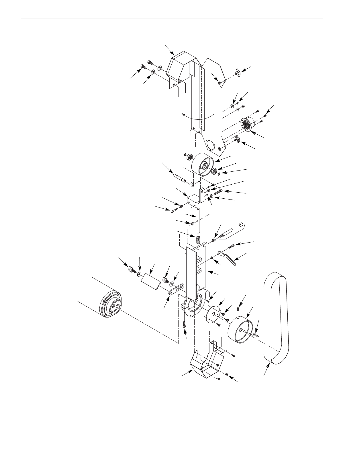
BELT I STALLATIO A D TRACKI G
Refer to Figure 8, page 8.
•Sanding belt should be replaced when worn, torn, or glazed.
Loosen belt cover knobs (Ref. No. 36) and open belt cover.
•Release belt tension by pulling up on tension handle Ref. No. 19).
Slide old belt off the drive and tracking wheels.
•Slide new belt over the drive and tracking wheels, center belt
on wheels, and pull down on tension handle to tension belt.
•Replace belt cover and tighten knobs.
•Rotate belt by hand to check tracking, belt should ride centered
on drive and tracking wheels. Adjust socket head bolt (Ref. No.
30) at top of tracking bracket to track belt properly. Be sure to
secure socket head bolts with hex nut (Ref. No. 22).
ADJUST BELT ASSEMBLY POSITIO
Refer to Figure 8, page 8.
The belt assembly can be adjusted from vertical to horizontal position.
•Loosen the belt housing bolt (Ref. No. 7) that clamps belt hous-
ing to motor
assembly.
•Tilt belt assembly to desired position (from vertical to horizontal).
Secure belt assembly position by tightening belt housing bolt.
ABRASIVE BELT FI ISHI G
•Finishing flat surfaces: Hold workpiece firmly with both hands,
keep fingers away from abrasive belt.
Use tool rest. Tool rest is used to position and stabilize work.
Keep end butted against tool rest and move work evenly across
abrasive belt. Use extra caution when finishing very thin pieces.
For finishing long pieces: remove tool rest. Apply only enough
pressure to allow abrasive belt to remove material.
•Finishing curved edges: Finish outside curves on flat portion of
abrasive belt.
ABRASIVE GRI DI G
•Keep a steady, moderate pressure on the work and keep it
moving at an even pace for smooth grinding.
•Pressing too hard overheats the motor and prematurely wears
down the grinding wheels.
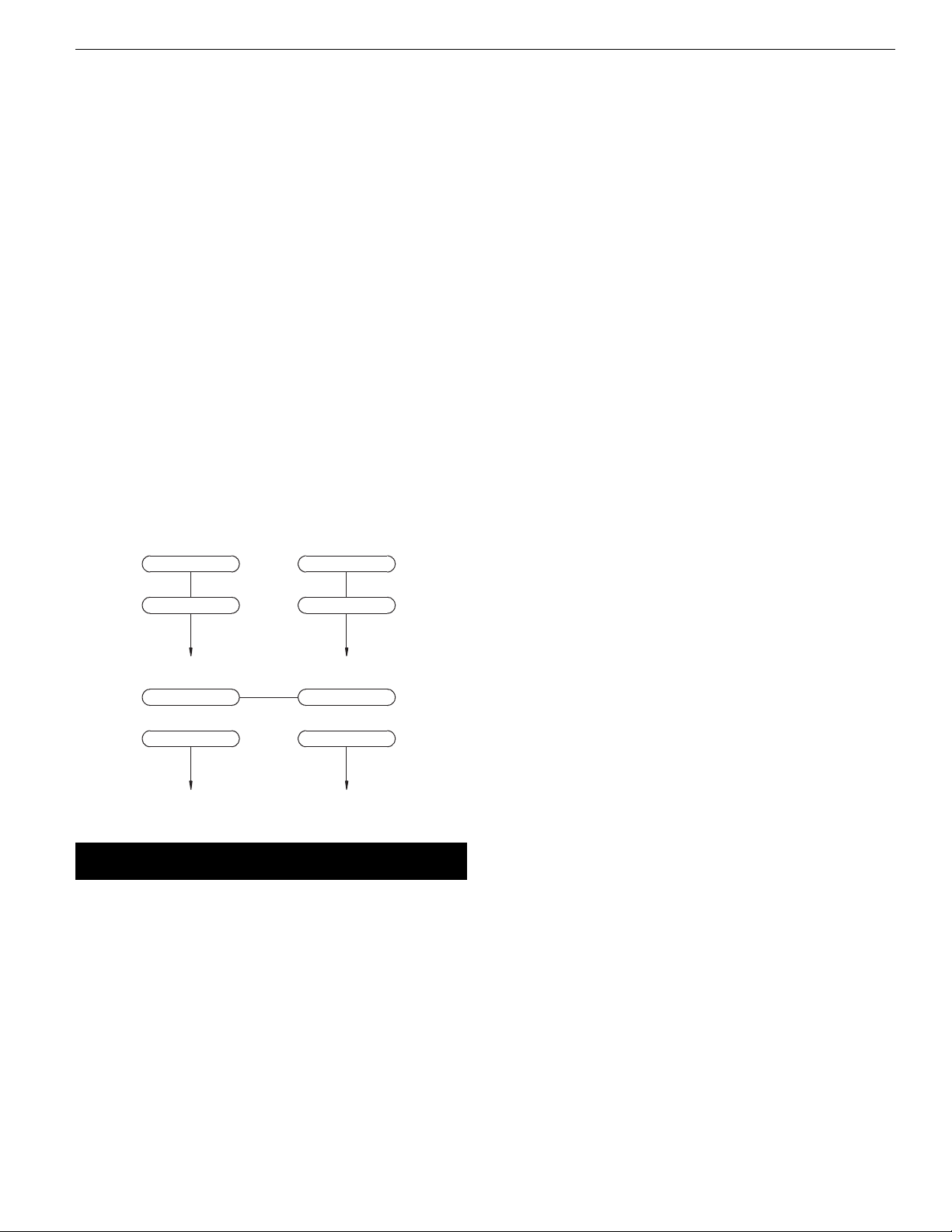
Figure 7 – Wiring Diagram
3-Red 2- ray
4-Yellow
1-Black
120V
240V
3-Red
1-Black
2- ray
4-Yellow
Palmgren Operating Manual & Parts List 82088

6
Palmgren Operating Manual & Parts List 82088
OPERATIO (CO TI UED)
•Note the original bevel angle on the item to be sharpened and
try to maintain that angle. Sharpening a cutting edge requires
removing burrs from edge.
•Deburring edge is done best by using the grinder to pull burr
from edge across the bevel angle.
•The grinding wheel should rotate into object being sharpened.
•Dip work into a coolant regularly to prevent overheating.
Overheating can weaken metals.
MAINTENANCE
WAR I G: Make certain that the unit is disconnected from
power source before attempting to service or remove any
component.
CLEA I G
•Keep machine and workshop clean. Do not allow sawdust to
accumulate on the tool.
•Keep wheels clean. Dirt on wheels will cause poor tracking and
belt slippage.
•Operate tool with dust collector to keep dust from
accumulating.
WAR I G: After sanding wood or non-metallic material, always
clean dust collector and guards of sawdust before grinding metal.
Sparks could ignite debris and cause a fire.
•Be certain motor is kept clean and is frequently vacuumed free
of dust.
•Use soap and water to clean painted parts, rubber parts and
plastic guards.
LUBRICATIO
•The shielded ball bearings in this tool are permanently
lubricated at the factory. They require no further lubrication.
•When operation seems stiff, a light coat of paste wax applied to
the belt table and disc table will make it easier to feed the work
while finishing.
•Do not apply wax to the belt platen. Belt could pick up wax and
deposit it on wheels causing belt to slip.
KEEP TOOL I REPAIR
•If power cord is worn, cut or damaged, have it replaced
immediately.
•Replace worn abrasives when needed.
•Replace any damaged or missing parts. Use parts list to order
parts.
•Any attempt to repair motor may create a hazard unless repair
is done by a qualified service technician.
GRI DI G WHEEL MAI TE A CE
•As wheels wear, tool rests should be positioned closer to the
face of the wheels.
•The gap between the wheel and the tool rest should not be
greater than 1/16”. When the wheels are worn to the extent that
the 1/16” maximum gap cannot be maintained, the wheels
should be replaced.
•Replacement wheels should have a minimum rated speed of at
least 3600 RPM.
•Maximum wheel diameter is 8”.
•To loosen nuts holding the wheels, disconnect power and push
a wood wedge between the tool rest and the wheel to keep
the shaft from turning. The threads on the right side of the
grinder (facing unit) are right hand; threads on the left side are
left hand. Tighten nuts securely before operating the grinder.
•For grinding efficiency, wheels should be dressed periodically,
especially if they become clogged from grinding soft metals.

7
Palmgren Operating Manual & Parts List 82088
SYMPTOM POSSIBLE CAUSE(S) CORRECTIVE ACTIO
Motor will not start
Motor will not start; fuses blown or
circuit breakers tripped
Motor fails to develop full power
(power output of motor decreases
rapidly with decrease in voltage at
motor terminals)
Motor overheats
Motor stalls
(resulting in blown fuses or
tripped circuit breakers)
Machine slows down while operating
Abrasive belt runs off top wheel
Excessive vibration
1. Blown line fuse or tripped circuit breaker
2. Low line voltage
3. Defective switch
4. Defective, blown capacitor
1. Overloading due to binding
2. Defective plug
3. Defective cord
4. Defective switch
1. Power line overloaded with lights,
appliances and other motors
2. Undersized wires or circuits too long
3. eneral overloading of power
company’s facilities
Motor overloaded
1. Short circuit in motor or loose
connections
2. Low voltage
3. Motor wired for different line voltage
4. Incorrect fuses or circuit breakers in power
line
5. Motor overloaded
Applying too much pressure to workpiece
Not tracking properly
1. Improper mounting of grinder or acces-
sories
2. rinding wheel out of balance
3. Improper wheel mounting
1. If fuse is blown, replace with fuse of
proper size. If breaker tripped, reset it
2. Check power supply for voltage and
correct as needed
3. Replace switch
4. Replace capacitor
1. Clean around wheels and shaft and/or
replace bearings
2. Replace plug
3. Replace cord
4. Replace switch
1. Reduce load on power line
2. Increase wire sizes, or reduce length
of wiring
3. Request a voltage check from power
company
Reduce load on motor.
1. Inspect connections in motor for loose or
shorted terminals or worn insulation on
lead wires
2. Correct the low line voltage conditions
3. Rewire motor as per line voltage
4. Install correct fuses or circuit breakers
5. Reduce load on motor
Ease up on pressure
See operation section
“Tracking Abrasive Belt”
1. Remount
2. Dress wheels or replace wheels
3. Remount wheels, but rotate one wheel
90º with respect to its previous position.
Other wheel should remain in its original
position
TROUBLESHOOTING

8
Palmgren Operating Manual & Parts List 82088
2
2
26
21
23
20
18
18
37
39
40
36
35
34
33
32
31 24
30
36
38
41
15
16
19
22
29
22
25
24
14
1
17
11
6
13
7
12
3
28
27
4
5
9
9
810
Figure 8 – Repair Parts Illustration for Belt Housing

9
1 5/16-18 x 1” Knob 25812.00 1
2 5/16” Flat washer *3
3 Tool rest 28670.00 1
4 3/8-16 x 1/2” Knob 25817.00 1
5 3/8” Flat washer *1
6 Bracket 31459.00 1
7 5/16-18 x 1” Socket head bolt *1
8 Lower guard 28664.00 1
9 #10-24 x 1/4” Flange screw 03210.00 7
10 Abrasive belt (80 grit) 30788.00 1
11 Key 28665.00 1
12 Drive pulley 28666.00 1
13 1/4-20 x 3/8” Set screw *1
14 1/4-20 x 1/2” Flange screw *3
15 Pivot stop bracket 28667.00 1
16 5 x 14mm Spring pin 15991.00 1
17 Platen 28668.00 1
18 1/4” Flat washer *4
19 Tension lever 28684.00 1
20 1/4-20 x 11⁄8” Socket head bolt *1
21 Stop rod with cap 28682.00 1
22 5/16”-18 Hex nut *2
23 Spring 28672.00 1
24 1/4”-20 Fiber hex nut *2
25 Bracket shaft 28681.00 1
26 1/4-20 x 11⁄4” Socket head bolt *1
27 Spring 28673.00 1
28 Idler bracket 28674.00 1
29 1/4-20 x 1/4” Set screw *1
30 5/16-18x11⁄4” Socket head bolt *1
31 #10-24 x 1/4” Set screw *2
32 Idler shaft 28675.00 1
33 Retaining ring 28680.00 2
34 6201LL Ball bearing 03862.00 2
35 Idler pulley 28679.00 1
36 1/4-20 x 3/8” Knob 25816.00 2
37 Dust chute 28678.00 1
38 1/4-20 x 1/4” Hex head bolt *2
39 uard 28676.00 1
40 5/16-18 x 3/8” Hex head bolt *2
41 5mm Push nut 31460.00 2
∆ Operator’s manual 37115.00 1
Recommended Accessories
∆ Heavy Duty Floor Stand 70102
REPLACEMENT PARTS LIST FOR BELT HOUSING
∆Not shown
* Standard hardware item, available locally.
Ref.
o. Description Part o. Qty.
Palmgren Operating Manual & Parts List 82088

10
Palmgren Operating Manual & Parts List 82088
2
26
21
23
20
15
15
18
1
16
16
17
38
39 35
36
37
32
34
33
31
30
40
29
29
29
29
29
22
25
24
19
14
41
42
43
9
6
11
8
13
13
78
12
3
28
27
4
4
5
8
10
Figure 9 – Repair Parts Illustration for Grinding Wheel and Motor

11
Palmgren Operating Manual & Parts List 82088
1 #10-24 x 7/8” Pan head screw *5
2 Wheel guard cover 24496.02 1
3 5/8”-11 Hex nut (LH) 00088.00 1
4 Wheel flange 24497.00 2
5 rinding wheel (36 grit) 02037.00 1
6 Switch 08066.01 2
7 Upper eye shield bracket (left) 25177.00 1
8 Eye shield kit 32290.00 1
9 Switch plate 28662.00 1
10 Spark guard 31456.00 1
11 Base bumper 23391.00 4
12 1/4-20 x 1/2” Knob 25816.00 1
13 3/8” Flat washer *1
14 3/8-16 x 1/2” Knob 25817.00 1
15 1/4-20 x 1/2” Hex head bolt *5
16 1/4” Lock washer *5
17 Wheel guard 26056.00 1
18 1/4-20 x 5/8” Hex head bolt *2
19 Bracket 31447.00 1
20 Tool rest 25813.00 1
21 5/16” Flat washer *3
22 5/16-18 x 1” Knob 25812.00 1
23 5-0.8mm Hex nut *4
24 #10 Serrated washer *4
25 End shield 16627.02 1
26 Wavy washer 16640.00 1
27 6203ZZ Ball bearing 01901.00 1
28 Centrifugal switch 25172.00 1
29 #10-24 x 1/4” Flange screw 03210.00 11
30 Stationary switch 25171.00 1
31 Armature †1
32 Stator with housing †1
33 6204ZZ Ball bearing 00989.00 1
34 End shield 28654.00 1
35 5-0.8 x 215mm Pan head screw 28655.00 4
36 Line cord 00090.00 1
37 Base †1
38 Strain relief 04055.00 1
39 Strain relief plate 28657.00 1
40 Capacitor clamp 16655.00 1
41 Capacitor cap 31472.00 1
42 Capacitor 26642.00 1
43 Base cover 24500.00 1
REPLACEMENT PARTS LIST FOR GRINDING WHEEL AND MOTOR
Ref.
o. Description Part o. Qty.
∆Not shown
* Standard hardware item, available locally.
† Not available as repair part.

Palmgren Operating Manual & Parts List 82088
WARRANTY
Palmgren warrants their products to be free of defects in material or workmanship. This warranty does not cover defects due
directly or indirectly to misuse, abuse, normal wear and tear, failure to properly maintain the product, heated, ground or otherwise altered, or
used for a purpose other than that for which it was intended. The warranty does not cover expendable and/or wear parts (i.e. v-belts, coated
screws, abrasives), damage to tools arising from alteration, abuse or use other than their intended purpose, packing and freight. The duration
of this warranty is expressly limited to one year parts and labor, unless otherwise noted below beginning from the date of delivery to the
original user. The Palmgren products carry the following warranties on parts with a 1 year warranty on labor:
•USA Machine vises – Lifetime
•IQ Machine vises – Lifetime
•Bench vises – Lifetime
•Positioning tables – Lifetime
•Bench grinders & buffers – 3 years
•Tapping machines – 2 years
•Drilling machines – 2 years
•Finishing machines – 2 years
•Band saws – 2 years
•Work stands – 2 years
•Arbor presses – 2 years
•Metal forming equipment – 2 years
•Accessories – 1 year
The obligation of Palmgren is limited solely to the repair or replacement, at our option, at its factory or authorized repair agent of any part
that should prove deficient. Purchaser must lubricate and maintain the product under normal operating conditions at all times. Prior to
operation
become familiar with product and the included materials, i.e. warnings, cautions and manuals. Failure to follow these instructions will
void the warranty.
This warranty is the purchaser’s exclusive remedy against Palmgren for any deficiency in its products. Under no circumstances is Palmgren
liable for any direct, indirect, incidental, special or consequential damages including lost profits in any way related to the use or inability to
use our products. This warranty gives you specific legal rights which may vary from state to state.
SERVICE & REPAIR
1. If a Palmgren product requires a repair or warranty service DO OT return the product to the place of purchase.
2. All warranty related work must be evaluated and approved by Palmgren.
3. Prior to returning any item the user must obtain factory approval and a valid R A number.
4. For instructions and R A number call toll free (800) 621-6145.
Table of contents
Other Palmgren Grinder manuals

Palmgren
Palmgren 82064 User manual

Palmgren
Palmgren 9682905 Instructions for use

Palmgren
Palmgren 82401 User manual

Palmgren
Palmgren 9682096 User manual

Palmgren
Palmgren 82066 User manual

Palmgren
Palmgren 82061C User manual

Palmgren
Palmgren 82121 User manual

Palmgren
Palmgren 82064A User manual

Palmgren
Palmgren 82102A User manual

Palmgren
Palmgren 9682096A User manual