Palmgren 9682096 User manual

Operating Manual & Parts List 9682096, 9682097 and 9682098
6˝, 8˝ and 10˝
variable speed
Bench Grinders
Read carefully and follow all safety rules and operating
instructions before first use of this product.
9642040.01-0117
9682096_9682097_9682098_oipm_En012_9642040.01 01/31/17 12:19 PM Page 1

DESCRIPTION
Palmgren’s variable speed bench grinders with inverter is equipped
with a totally enclosed ball bearing motor. Armature assembly is
dynamically balanced for smooth operation. Motor housing is
compact so long pieces of work can press against both wheel with-
out touching the motor frame. Removable wheel guard covers
allow for easy changing of wheels. Tool rests are adjustable for
wheel wear and angle grinding. Grinder comes complete with
spark guards, safety Eyeshields, and dust collection hose.
SPECIFICATIONS
9682096 9682097 9682098
Horsepower 1/2 1 1.5
Voltage 115/240 115/240 115/240
Amperes 7/3.5 12/6 14/7
Hertz 50-60 50-60 50-60
Phase Single Single Single
RPM 900-3600 900-3600 900-2400
Rotation (viewed from left) Clockwise Clockwise Clockwise
Wheel Diameter 6˝ 8˝ 10˝
Wheel Bore 1/2˝ 5/8˝ 1˝
Wheel Face 3/4˝ 1˝ 1˝
Aluminum Oxide Vitrified Wheels
36 Coarse and 60 Medium Yes Yes Yes
CSA US 180264 Yes Yes Yes
STRUCTURAL REQUIREMENTS
Make sure all supporting structures and load attaching devices are
strong enough to hold your intended loads. If in doubt, consult a
qualified structural engineer.
ELECTRICAL REQUIREMENTS
9682096 115/240 Volts 7/3.5 Amps 1Φ50-60 Hz
9682097 115/240 Volts 12/6 Amps 1Φ50-60 Hz
9682098 115/240 Volts 14/7 Amps 1Φ50-60 Hz
The standard allowable voltage variation is plus or minus 10%.
TOOLS NEEDED:
Standard mechanic’s hand tool set.
UNPACKING
Carton should be handled with care to avoid damage from drop-
ping, bumping,etc. Store and unpack carton with correct side up.If
any damage or loss has occurred, claim must be filed with carrier
immediately. Check for completeness. Immediately report missing
parts to dealer.
To be certain the grinding wheels have not been damaged in ship-
ment, strike the edges slightly with a metal object. A ringing sound
indicates a good wheel, but a dull noise may signal a fracture.
WARNING: If you suspect a wheel of being fractured, replace it
immediately. Fractured wheels may shatter, causing serious injury.
CONTENTS:
• Bench Grinder
A 3/8˝-16 x 3/4˝ Hex Bolt (2)
B 3/8˝ Flat Washer (4)
C Tool Rest Bracket (2)
D Tool Rest (2)
E 5/16˝ Flat Washer (2)
F 5/16˝-18 x 1˝ Knob (2)
G #10-24 x 3/8˝ Pan Head Screw (4)
H Upper Eyeshield Bracket (2)
I Eyeshield (2)
J Lower Eyeshield Bracket (2)
K 1/4˝-20 x 1/2˝ Knob (2)
L Spark Guard (2)
M 3/8˝-16 x 1/2˝ Knob (2)
• Dust Collector Hose (1)
• Operating Instructions & Parts Manual (1)
UNPACK:
• Open carton and carefully remove Bench Grinder components
from packing material. Do not discard packing materials until
after unit has been inspected for damage and completeness.
Locate loose parts and set aside.
INSPECT:
• After unpacking the unit, carefully inspect for any damage that
may have occurred during transit. Check for loose, missing or
damaged parts. Shipping damage claims must be filed with the
carrier.
• All tools should be visually inspected before use, in addition to
regular periodic maintenance inspections.
• Be sure that the voltage labeled on the unit matches your
power supply.
2
Palmgren Operating Manual & Parts List 9682096, 9682097 and 9682098
Figure 1 – Left Tool Rest and Eyeshield Assembly
J
G
L
M
C
B
B
D
E
F
A
K
I
H
9682096_9682097_9682098_oipm_En012_9642040.01 01/31/17 12:19 PM Page 2

3
SAFETY RULES
WARNING: For your own safety, read all of the instructions and
precautions before operating tool.
PROPOSITION 65 WARNING: Some dust created by using power
tools contain chemicals known to the state of California to cause
cancer, birth defects or other reproductive harm.
Some examples of these chemicals are:
• Lead from lead-based paints.
• Crystalline silica from bricks and cement and other masonry
products.
• Arsenic and chromium from chemically-treated lumber.
Your risk from these exposures varies, depending on how often you
do this type of work.To reduce your exposure to these chemicals:
work in a well ventilated area and work with approved safety
equipment. Always wear OSHA/NIOSH approved, properly fitting
face mask or respirator when using such tools.
WARNING: Always follow proper operating procedures as defined
in this manual even if you are familiar with the use of this or similar
tools. Remember that being careless for even a fraction of a second
can result in severe personal injury.
BE PREPARED FOR JOB
• Wear proper apparel. Do not wear loose clothing,gloves, neck-
ties, rings, bracelets or other jewelry which may get caught in
moving parts of machine.
• Wear protective hair covering to contain long hair.
• Wear safety shoes with non-slip soles.
• Wear safety glasses complying with United States ANSI Z87.1.
Everyday glasses have only impact resistant lenses.They are
NOT safety glasses.
• Wear face mask or dust mask if operation is dusty.
• Be alert and think clearly.Never operate power tools when tired,
intoxicated or when taking medications that cause drowsiness.
PREPARE WORK AREA FOR JOB
• Keep work area clean. Cluttered work areas invite accidents.
• Do not use power tools in dangerous environments. Do not use
power tools in damp or wet locations. Do not expose power
tools to rain.
• Work area should be properly lighted.
• Proper electrical plug should be plugged directly into properly
grounded, three-prong receptacle.
• Extension cords should have a grounding prong and the three
wires of the extension cord should be of the correct gauge.
• Keep visitors at a safe distance from work area.
• Keep children out of workplace. Make workshop childproof. Use
padlocks, master switches or remove switch keys to prevent any
unintentional use of power tools.
TOOL SHOULD BE MAINTAINED
• Always unplug tool prior to inspection.
• Consult manual for specific maintaining and adjusting proce-
dures.
• Keep tool lubricated and clean for safest operation.
• Remove adjusting tools.Form habit of checking to see that ad-
justing tools are removed before switching machine on.
• Keep all parts in working order.Check to determine that the
guard or other parts will operate properly and perform their
intended function.
• Check for damaged parts. Check for alignment of moving parts,
binding, breakage, mounting and any other condition that may
affect a tool’s operation.
• A guard or other part that is damaged should be properly re-
paired or replaced. Do not perform makeshift repairs. (Use parts
list provided to order repair parts.)
KNOW HOW TO USE TOOL
• Use right tool for job. Do not force tool or attachment to do a
job for which it was not designed.
• Disconnect tool from power when changing accessories such as
grinding wheels, buffing wheels and the like.
• Avoid accidental start-up.Make sure that the switch is in the off
position before plugging in.
• Do not force tool.It will work most efficiently at the rate for
which it was designed.
• Keep hands away from moving parts and grinding surfaces.
• Never leave a tool running unattended.Turn the power off and
do not leave tool until it comes to a complete stop.
• Do not overreach.Keep proper footing and balance.
• Never stand on tool. Serious injury could occur if tool is tipped
over.
• Know your tool. Learn the tool’s operation, application and spe-
cific limitations.
• Use recommended accessories.Understand and obey all safety
instructions supplied with accessories.The use of improper ac-
cessories may cause risk of injury to persons.
• Do not over tighten wheel nut. Replace cracked wheel immedi-
ately. Use only flanges supplied with the grinder.
• Adjust distance between wheel and tool rest to maintain 1/16”
or less gap.
• Handle the workpiece correctly.Whenever possible, use tool
rest to support workpiece during grinding operation.Turn tool
off if it jams.
• Always use guards and eyeshields.
• Clean grinding dust from beneath tool frequently.
CAUTION: Think safety! Safety is a combination of operator com-
mon sense and alertness at all times when tool is being used.
ASSEMBLY
Refer to Figure 1, page 2.
Parts to be fastened to the unit should be located and accounted
for (See content list and figure 1, page 2).
CAUTION: Do not attempt assembly if parts are missing.Use this
manual to order repair parts.
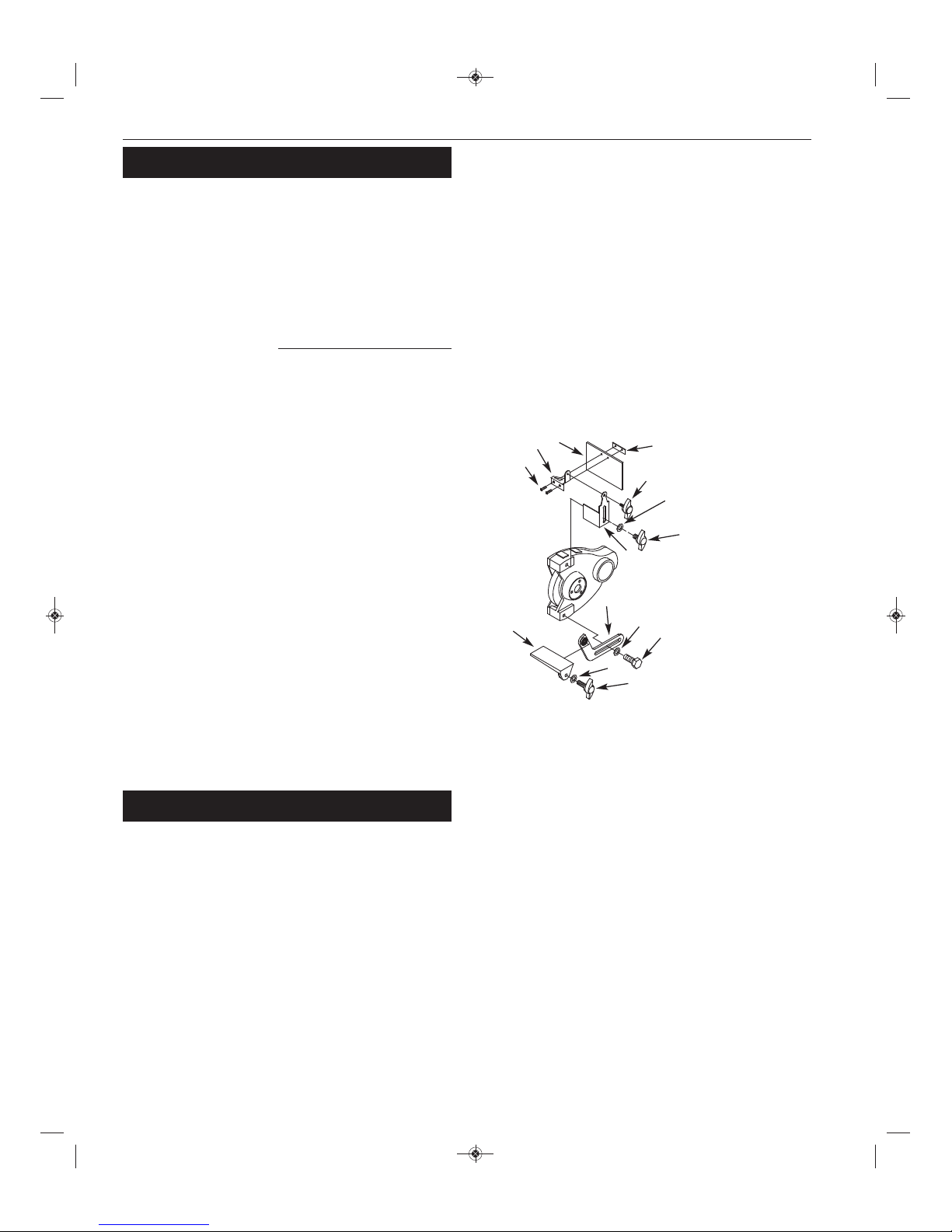
TOOL REST ASSEMBLY
1. Place tool rest (D) over tool rest bracket and secure in position
with 5/16˝ flat washer (E) and 5/16-18 x 1˝ knob (F).
2. Attach tool rest bracket to the bottom of the left wheel guard
using one 3/8˝-16 x 3/4˝ hex head bolt (A) and one 3/8˝ flat
washer (B). Make sure that the slot of the bracket is located over
the raised boss on the guard.Tighten bolts finger tight.
3. Position tool rest so that distance between tool rest and grind-
ing wheel is less than 1/16˝. Reposition angle of tool rest if
necessary.Secure all knobs and bolts.
4. Mount right tool rest in a similar manner.
Palmgren Operating Manual & Parts List 9682096, 9682097 and 9682098
9682096_9682097_9682098_oipm_En012_9642040.01 01/31/17 12:19 PM Page 3

4
ASSEMBLY (CONTINUED)
EYESHIELD ASSEMBLY
1. Attach spark guard (L) to left wheel guard using 3/8˝-16 x 1/2˝
knob (M) and 3/8˝ flat washer (B).
2. Mount left upper eyeshield bracket (H) to eyeshield (I) using
two #10-24 x 3/8˝ pan head screws (G) and lower eyeshield
bracket (J).
NOTE: Left upper eyeshield bracket is stamped “L”for
identification.
3. Slide 1/4˝-20 x 1/2˝ knob (K) through hole at top of left spark
guard (L) into upper eyeshield bracket (H) and secure in
position.
4. Locate eyeshield in desired position for protecting operator and
secure all knobs and bolts.
5. Mount right eyeshield assembly in a similar manner.
DUST COLLECTOR HOSE
A dust collector hose has been provided with grinder. Slide hoses
onto sides of T-connector and flanges. Mount the hose by sliding
the flanges at each end over the exhaust ports on the left and right
wheel guards. Attach 2½˝ shop vacuum hose to collector hose. Be
sure hose is mounted securely.
DANGER: Be sure to empty shop vacuum of all flammable mate-
rial (flammable liquids and vapors,paper,wood, plastic, etc.) before
connecting vacuum to grinder. Hot sparks from grinder may ignite
flammable materials in shop vacuum.
OPTIONAL GRINDER LIGHT (MODEL 9682904)
Position light bracket assembly over bosses provided on wheel
guard.Bosses are tapped to receive two 1/4˝-20 screws. Fasten
bracket assembly to wheel guard with two screws provided with
light.
INSTALLATION
MOUNT GRINDER
1. Mount grinder to a solid horizontal surface (hardware not pro-
vided). If mounted to metal pedestal, align mounting holes with
corresponding holes in pedestal. Insert a 1/4˝-20 x 1¼˝ hex head
bolt with flat washer through base of grinder. From bottom of
pedestal, place a 1/4˝ flat washer and 1/4˝-20 hex nut onto the
bolt.Tighten only until space between grinder base and
pedestal is 1/8˝. Using second nut on each bolt, jam tighten
against the first to prevent loosening by vibration.
2. To mount grinder to wooden bench top, use 1/4˝ x 1¼˝ wood
screws with flat washers beneath heads.Tighten screws until
space between grinder base and bench top is 1/8˝.
GROUNDING INSTRUCTIONS
WARNING: Improper connection of equipment grounding con-
ductor can result in the risk of electrical shock. Equipment should
be grounded while in use to protect operator from electrical shock.
Check with a qualified electrician if grounding instructions are not
understood or if in doubt as to whether the tool is properly
grounded.
This grinder is equipped with an approved 3-conductor cord rated
at 300V and a 3-prong,grounding type plug (See Figure 2) for your
protection against shock hazards.
Grounding plug should be plugged directly into a properly in-
stalled and grounded 3-prong grounding-type receptacle (See
Figure 2).
Do not remove or alter grounding prong in any manner. In the
event of a malfunction or breakdown, grounding provides a path of
least resistance for electrical shock.
WARNING: Do not permit fingers to touch the terminals of plug
when installing or removing from outlet.
Plug must be plugged into matching outlet that is properly in-
stalled and grounded in accordance with all local codes and ordi-
nances. Do not modify plug provided.If it will not fit in outlet, have
proper outlet installed by a qualified electrician.
Inspect tool cords periodically, and, if damaged, have repaired by an
authorized service facility.
Green (or green and yellow) conductor in cord is the grounding
wire. If repair or replacement of the electric cord or plug is neces-
sary,do not connect the green (or green and yellow) wire to a live
terminal.
Where a 2-prong wall receptacle is encountered, it must be re-
placed with a properly grounded 3-prong receptacle installed in
accordance with National Electric Code and local codes and
ordinances.
WARNING: This work should be performed by a qualified
electrician.
A temporary 3-prong to 2-prong grounding adapter (See Figure 3)
is available for connecting plugs to a two pole outlet if it is properly
grounded.
Do not use a 3-prong to 2-prong grounding adapter unless permit-
ted by local and national codes and ordinances.
(A 3-prong to 2-prong grounding adapter is not permitted in
Canada.) Where permitted, the rigid green tab or terminal on the
side of the adapter must be securely connected to a permanent
electrical ground such as a properly grounded water pipe,a prop-
erly grounded outlet box or a properly grounded wire system.
Many cover plate screws, water pipes and outlet boxes are not
properly grounded.To ensure proper ground, grounding means
must be tested by a qualified electrician.
Palmgren Operating Manual & Parts List 9682096, 9682097 and 9682098
Figure 3 – 2-Prong Receptacle with Adapter
Grounding Lug
Adapter
3-Prong Plug
2-Prong Receptacle
Make sure this is
Connected to a known
Grounded Receptacle
Figure 2 – 3-Prong Receptacle
Properly Grounded Outlet
Grounding Prong
3-Prong Plug
9682096_9682097_9682098_oipm_En012_9642040.01 01/31/17 12:19 PM Page 4


SYMPTOM POSSIBLE CAUSE(S) CORRECTIVE ACTION
TROUBLESHOOTING
6
Palmgren Operating Manual & Parts List 9682096, 9682097 and 9682098
Grinder won’t start
Excessive vibration
Motor overheating
Fuses are being blown or circuit
breakers are being tripped
Grinder will not operate in
variable speed mode
1. Blown line fuse or tripped circuit breaker
2. Low line voltage
3. Material wedged between wheel
and guard
4. Defective switch
5. Defective, blown capacitor
6. Defective circuit board
1. Improper mounting of grinder or
accessories
2. Grinding wheel out of balance
3. Improper wheel mounting
1. Excess pressure required to grind
material
2. Grinding on side of wheel
3. Motor not turning freely (without power)
1. Overloading due to binding
2. Defective plug
3. Defective cord
4. Defective switch
5. Faulty internal wiring
1. Defective variable speed switch
2. Defective sensor
3. Defective circuit board
1. If fuse is blown, replace with fuse of proper size.If
breaker tripped,reset it
2. Check power supply for voltage and
correct as needed
3. Turn grinder off and remove material
4. Replace switch
5. Replace capacitor
6. Replace circuit board
1. Remount
2. Dress wheels or replace wheels
3. Remount wheels, but rotate one wheel 90º with re-
spect to its previous position. Other wheel should
remain in its original position
1. Dress wheel or replace wheel with one of proper
grit
2. Grind only on face of wheel
3. Clean around wheels and shaft and/or replace
bearings
1. Clean around wheels and shaft and/or replace
bearings
2. Replace plug
3. Replace cord
4. Replace switch
5. Contact authorized Palmgren Service Center
1. Replace switch
2. Replace sensor
3. Replace circuit board
9682096_9682097_9682098_oipm_En012_9642040.01 01/31/17 12:19 PM Page 6

7
Palmgren Operating Manual & Parts List 9682096, 9682097 and 9682098
NOTES:
9682096_9682097_9682098_oipm_En012_9642040.01 01/31/17 12:19 PM Page 7


9
Palmgren Operating Manual & Parts List 9682096, 9682097 and 9682098
Repair Parts List for Bench Grinders
( ) Not shown.
(†) Not available as repair part.
(*) Standard hardware item,available locally.
1 1/4"-20 x 3/4" Pan Head Screw - * 10
1 #10-24 x 1/2" Pan Head Screw **- 10
2 Wheel Guard 9625959.01 9626056.01 9626057.01 2
3 Spark Guard (set of 2) 9625814.00 9625815.00 9625815.00 1
4 Wheel Guard Cover 9624464.03 9624496.03 9616911.03 2
210.292246900.708526900.6085269egnalF5
6 1/2"-12 Hex Nut (RH Thread) 9600548.00 - - 1
6 5/8"-11 Hex Nut (RH Thread) - 9600088.00 - 1
6 1"-8 Hex Nut (RH Thread) --9600110.00 1
7 Inner Wheel Flange 9617316.00 9624498.00 9624481.00 2
8 Grinding Wheel (36 Coarse Grit) * * * 1
9 Grinding Wheel (60 Medium Grit) * * * 1
10 5/16"-18 x 1" Knob 9625812.00 9625812.00 9625812.00 2
11 3/8"-16 x 3/4" Hex Head Bolt *** 2
12 3/8" Flat Washer * * * 4
13 5/16" Flat Washer *** 2
14 1/4"-20 x 1/2" Knob 9625816.00 9625816.00 9625816.00 2
15 Dust Collector Hose 9608070.01 9608070.00 9608070.02 1
16 Tool Rest (Left) 9625813.00 9625813.00 9625813.00 1
17 Bracket (Left) 9625810.00 9631447.00 9626290.00 1
19 3/8"-16 x 1/2" Knob 9625817.00 9625817.00 9625817.00 2
20 1/2"-12 Hex Nut (LH Thread) 9600064.00 - - 1
20 5/8"-11 Hex Nut (LH Thread) - 9600087.00 - 1
20 1"-8 Hex Nut (LH Thread) - - 960111.00 1
21 Upper Eyeshield Bracket (Left) 9625177.00 9625177.00 9625177.00 1
22 Upper Eyeshield Bracket (Right) 9625188.00 9625188.00 9625188.00 1
23 Eyeshield Kit (Set of 2) 9632290.00 9632290.00 9632290.00 1
25 Tool Rest (Right) 9625825.00 9625825.00 9625825.00 1
27 1/4"-20 x 3/8" Flange Screw * - - 6
27 1/4"-20 x 1/2" Hex Head Bolt - * - 6
27 5/16"-18 x 5/8" Hex Head Bolt --* 6
1†††rotoM33
200.619616900.660106900.6601069temmorG43
100.090006900.090006900.7600069droCeniL53
0.106106900.5504069feileRniartS63 0 9601601.00 1
37 #10-24 x 1/4" Flange Screw * * - 6
37 M6 x 10mm Flange Screw --* 6
1†††esaB83
100.919616900.005426900.8573269revoCesaB04
41 1/4" Lock Washer * * - 10
41 5/16" Lock Washer --* 10
42 1/4"-20 Hex Nut **- 4
42 5/16"-18 Hex Nut --* 4
43 M3 x 10mm Screw *** 4
44 Inverter & Control Panel Assembly 9640118.01 9640118.02 9640118.03 1
45 #10 Serrated Washer * * * 4
46 Base Bumper 9623391.00 9623991.00 9623991.00 4
48 Bracket (Right) 9625826.00 9631448.00 9626291.00 1
Recommended Accessories
Cast Iron Tool Stand 9670101 9670101 9670101
Grinder Light 9682904 9682904 9682904
Grinding Wheel Dresser 9682901 9682901 9682901
Large Grinding Wheel Dresser 9682902 9682902 9682902
rof.oNtraProf.oNtraProf.oNtraP.feR
.ytQ890286979028696902869noitpircseD.oN
rof.oNtraProf.oNtraProf.oNtraP.feR
.ytQ890286979028696902869noitpircseD.oN
9682096_9682097_9682098_oipm_En012_9642040.01 01/31/17 12:19 PM Page 9

10
Palmgren Operating Manual & Parts List 9682096, 9682097 and 9682098
NOTES:
9682096_9682097_9682098_oipm_En012_9642040.01 01/31/17 12:19 PM Page 10

11
Palmgren Operating Manual & Parts List 9682096, 9682097 and 9682098
NOTES:
9682096_9682097_9682098_oipm_En012_9642040.01 01/31/17 12:19 PM Page 11

WARRANTY
Palmgren warrants their products to be free of defects in material or workmanship.This warranty does not cover defects due directly or
indirectly to misuse, abuse, normal wear and tear, failure to properly maintain the product, heated, ground or otherwise altered, or used for a
purpose other than that for which it was intended. The warranty does not cover expendable and/or wear parts (i.e. v-belts, coated screws,
abrasives), damage to tools arising from alteration, abuse or use other than their intended purpose, packing and freight. The duration of this
warranty is expressly limited to one year parts and labor, unless otherwise noted below beginning from the date of delivery to the original
user. The Palmgren products carry the following warranties on parts with a 1 year warranty on labor:
•USA Machine vises – Lifetime
•IQ Machine vises – Lifetime
•Bench vises – Lifetime
•Positioning tables – Lifetime
•Bench grinders & buffers – 3 years
•Tapping machines – 2 years
•Drilling machines – 2 years
•Finishing machines – 2 years
•Band saws – 2 years
•Work stands – 2 years
•Arbor presses – 2 years
•Metal forming equipment – 2 years
•Accessories – 1 year
The obligation of Palmgren is limited solely to the repair or replacement, at our option, at its factory or authorized repair agent of any part
that should prove deficient. Purchaser must lubricate and maintain the product under normal operating conditions at all times. Prior to
operation become familiar with product and the included materials, i.e. warnings, cautions and manuals. Failure to follow these
instructions will void the warranty.
This warranty is the purchaser’s exclusive remedy against Palmgren for any deficiency in its products. Under no circumstances is Palmgren
liable for any direct, indirect, incidental, special or consequential damages including lost profits in any way related to the use or inability to
use our products.This warranty gives you specific legal rights which may vary from state to state.
SERVICE & REPAIR
1. If a Palmgren product requires a repair or warranty service DO NOT return the product to the place of purchase.
2. All warranty related work must be evaluated and approved by Palmgren.
3. Prior to returning any item the user must obtain factory approval and a valid RGA number.
4. For instructions and RGA number call toll free (800) 827-3398.
Palmgren Operating Manual & Parts List 9682096, 9682097 and 9682098
9682096_9682097_9682098_oipm_En012_9642040.01 01/31/17 12:19 PM Page 12
This manual suits for next models
2
Table of contents
Other Palmgren Grinder manuals

Palmgren
Palmgren 82061B User manual

Palmgren
Palmgren 82102A User manual

Palmgren
Palmgren 9682096A User manual

Palmgren
Palmgren 82121 User manual

Palmgren
Palmgren 82064 User manual

Palmgren
Palmgren 9682905 Instructions for use

Palmgren
Palmgren 82401 User manual

Palmgren
Palmgren 82088 User manual

Palmgren
Palmgren 82064A User manual

Palmgren
Palmgren 82061C User manual