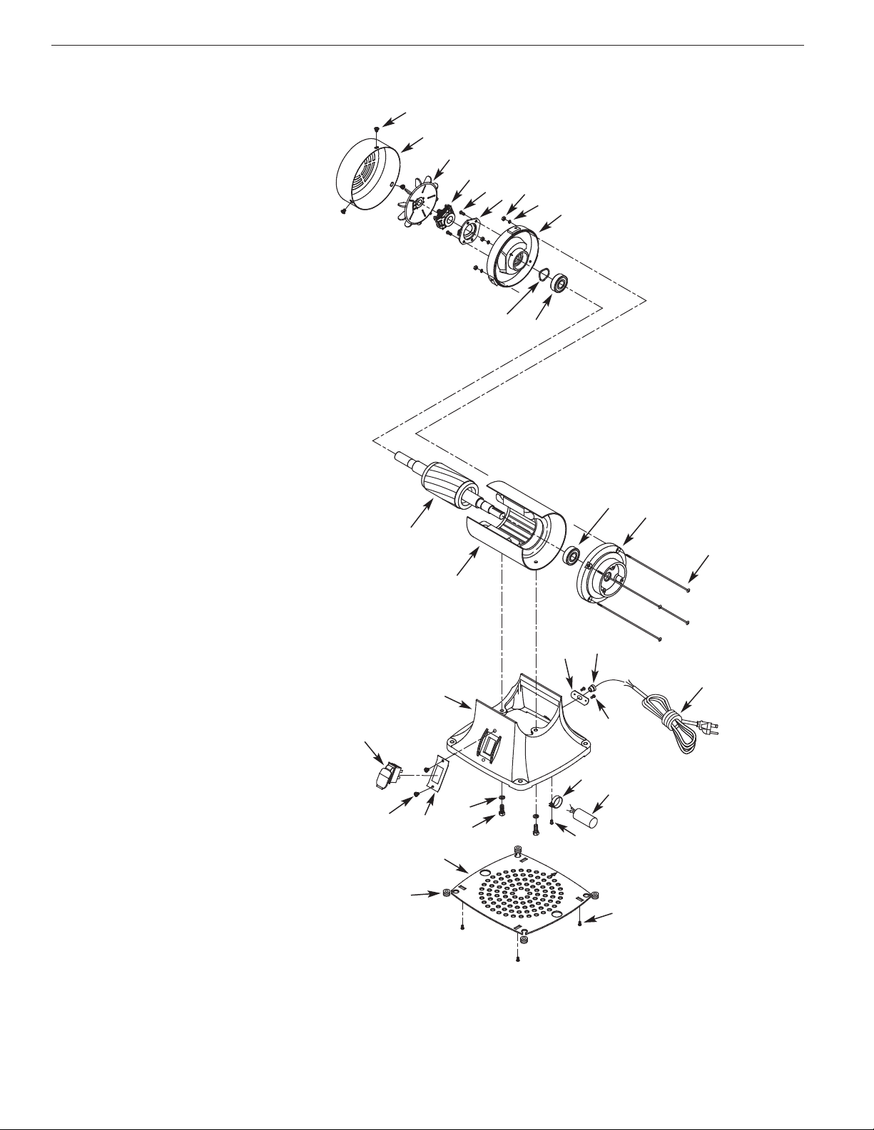
Palmgren 82401 User manual

operat ng manual & parts l st 82401, 82402 & 82404
1″, 2″ & 4″
BELT GRINDERS
Read carefully and follow all safety rules and operating instructions before
first use of this product.
37113.00-0213

DESCRIPTION
Palmgren Belt Grinders are used for grinding, deburring, squaring,
polishing and finishing metals, woods and plastics. Belt grinders
have totally enclosed, fan-cooled direct drive motors. Belt housing
swivels from vertical to horizontal for grinding long workpieces.
Features include a fully adjustable tool rest, quick release belt ten-
sion and tracking mechanism, OS A compliant safety guard with
dust collection port and easy opening side door for belt changes.
UNPACKING
Check for shipping damage. If damage has occurred, a claim must
be filed with the carrier immediately. Check for completeness.
Immediately report missing parts to dealer.
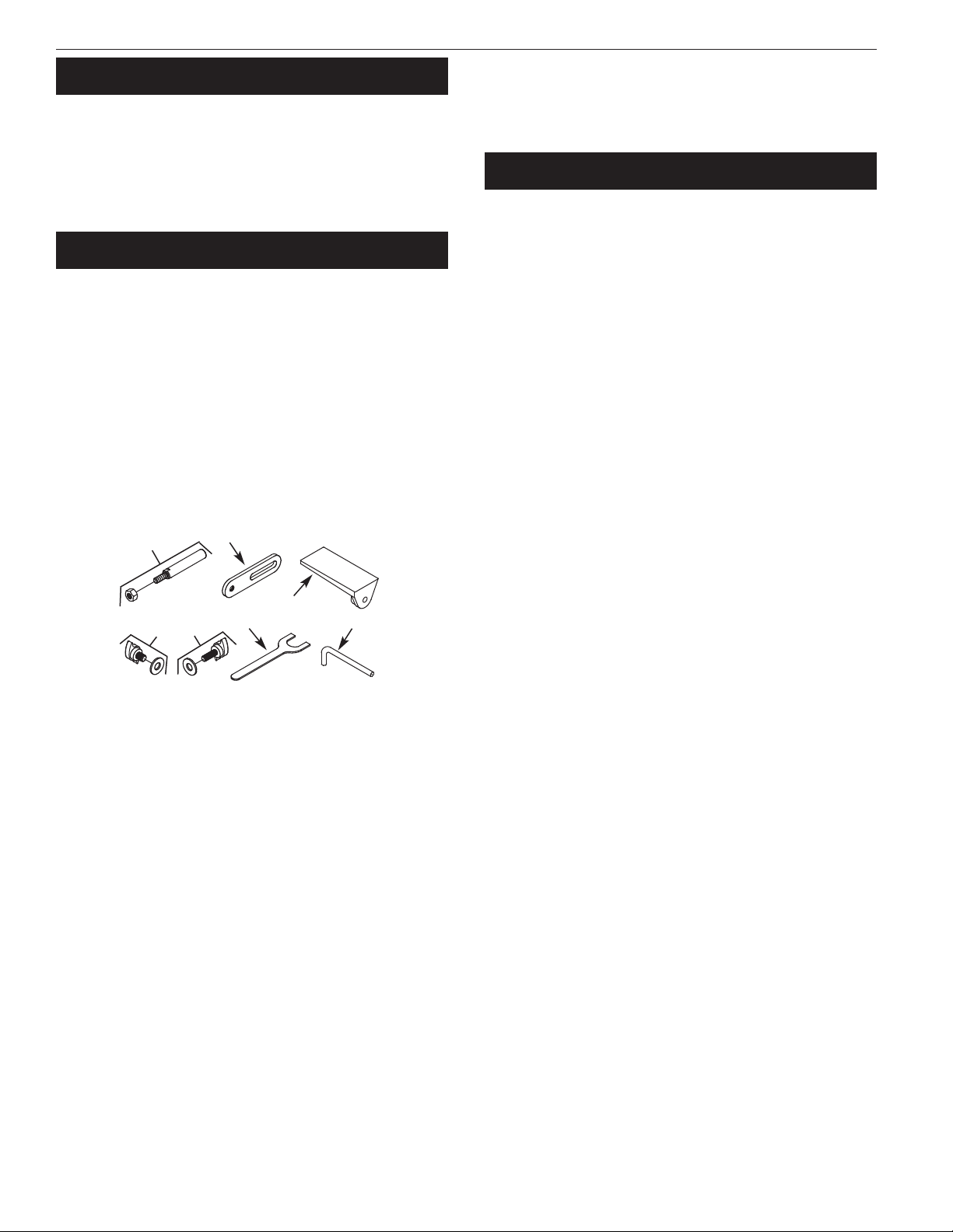
The grinder comes assembled as one unit. Additional parts which
need to be fastened to grinder should be located and accounted
for before assembling.
A Stop rod with hex nut
B Bracket
C Tool rest
D 3/8 x 16 x 1/2” Knob with flat washer
E 5/16-18 x 1“ Knob with flat washer
F 12mm Open end wrench
G 6mm ex wrench
SPECIFICATI NS
82401 - 1” Belt Grinder
Belt size . . . . . . . . . . . . . . . . . . . . . . . . . . . . . . . . . . . . . . . . . . . .1 x 42”, 80 grit
Belt platen area . . . . . . . . . . . . . . . . . . . . . . . . . . . . . . . . . . . . . . . . . .10 x 11
⁄2”
Belt speed . . . . . . . . . . . . . . . . . . . . . . . . . . . . . . . . . . . . . . . . . . . . . .1800 FPM
Dust collection chute . . . . . . . . . . . . . . . . . . . . . . . . . . . . . . . . .2” diameter
Dimensions (L x W x ) . . . . . . . . . . . . . . . . . . . . . . . . . . . . . . .22 x 16 x 24”
Switch . . . . . . . . . . . . . . . . . . . . . . . . . . . . . . . . . . . . . . . . .DP, Locking rocker
Motor . . . . . . . . . . . . . . . . . . . .1/2 p, 115/230V, 5/2.5 AMPS, 1725 RPM
Weight . . . . . . . . . . . . . . . . . . . . . . . . . . . . . . . . . . . . . . . . . . . . . . . . . . . . .46 lbs
82402 - 2” Belt Grinder
Belt size . . . . . . . . . . . . . . . . . . . . . . . . . . . . . . . . . . . . . . . . . . . .2 x 48”, 80 grit
Belt platen area . . . . . . . . . . . . . . . . . . . . . . . . . . . . . . . . . . . . . . .121
⁄4x 21
⁄2”
Belt speed . . . . . . . . . . . . . . . . . . . . . . . . . . . . . . . . . . . . . . . . . . . . . .4500 FPM
Dust collection chute . . . . . . . . . . . . . . . . . . . . . . . . . . . . . . . . .2” diameter
Dimensions (L x W x ) . . . . . . . . . . . . . . . . . . . . . . . . . . . . .25 x 161
⁄2x 26”
Switch . . . . . . . . . . . . . . . . . . . . . . . . . . . . . . . . . . . . . . . . .DP, Locking rocker
Motor . . . . . . . . . . . . . . . . . . . .3/4 p, 115/230V, 7/3.5 AMPS, 3450 RPM
Weight . . . . . . . . . . . . . . . . . . . . . . . . . . . . . . . . . . . . . . . . . . . . . . . . . . . . .56 lbs
82404 - 4” Belt Grinder
Belt size . . . . . . . . . . . . . . . . . . . . . . . . . . . . . . . . . . . . . . . . . . . .4 x 36”, 80 grit
Belt platen area . . . . . . . . . . . . . . . . . . . . . . . . . . . . . . . . . . . . . . . . .73
⁄8x 41
⁄2”
Belt speed . . . . . . . . . . . . . . . . . . . . . . . . . . . . . . . . . . . . . . . . . . . . . .3600 FPM
Dust collection chute . . . . . . . . . . . . . . . . . . . . . . . . . . . . . . . . .2” diameter
Dimensions (L x W x ) . . . . . . . . . . . . . . . . . . . . . . . . . . . . . . .19 x 20 x 21”
Switch . . . . . . . . . . . . . . . . . . . . . . . . . . . . . . . . . . . . . . . . .DP, Locking rocker
Motor . . . . . . . . . . . . . . . . . . . .3/4 p, 115/230V, 7/3.5 AMPS, 3450 RPM
Weight . . . . . . . . . . . . . . . . . . . . . . . . . . . . . . . . . . . . . . . . . . . . . . . . . . . . .55 lbs
SAFETY RULES
WARNING: For your own safety, read operating instructions man-
ual before operating tool.
CAUTI N: Always follow proper operating procedures as defined in
this manual even if you are familiar with use of this or similar tools.
Remember that being careless for even a fraction of a second can
result in severe personal injury.
WARNING: Some dust created by power sanding, sawing, grind-
ing, drilling and other construction activities contains chemicals
known to cause cancer, birth defects or other reproductive harm.
Some examples of these chemicals are:
•Lead from lead-based paints.
•Crystalline silica from bricks and cement and other masonry
products.
•Arsenic and chromium from chemically-treated lumber.
Your risk from these exposures vary, depending on how often you
do this type of work. To reduce your exposure to these chemicals:
work in a well ventilated area and work with approved safety
equipment. Always wear SHA/NI SH approved, properly fitting
face mask or respirator when using such tools.
BE PREPARED F R J B
•Wear proper apparel. Do not wear loose clothing, gloves, neck-
ties, rings, bracelets or other jewelry which may get caught in
moving parts of machine.
•Wear protective hair covering to contain long hair.
•Wear safety shoes with non-slip soles.
•Wear safety glasses complying with United States ANSI Z87.1.
Everyday glasses have only impact resistant lenses. They are
NOT safety glasses.
•Wear face mask or dust mask if operation is dusty.
•Be alert and think clearly. Never operate power tools when
tired, intoxicated or when taking medications that cause
drowsiness.
PREPARE W RK AREA F R J B
•Keep work area clean. Cluttered work areas and work benches
invite accidents.
•Do not use power tools in dangerous environments. Do not use
power tools in damp or wet locations. Do not expose power
tools to rain.
•Work area should be properly lighted.
•Proper electrical plug should be plugged directly into properly
grounded, three-prong receptacle.
•Extension cords should have a grounding prong and the three
wires of the extension cord should be of the correct gauge.
•Keep visitors at a safe distance from work area.
•Keep children out of the workplace. Make workshop childproof.
Use padlocks, master switches or remove switch keys to pre-
vent any unintentional use of power tools.
T L SH ULD BE MAINTAINED
•Always unplug tool prior to inspection.
•Consult manual for specific maintaining and adjusting proce-
dures.
2
Palmgren Operating Manual & Parts List 82401, 82402 & 82404
Figure 1 – Unpacking
AB
DEFG
C

3
SAFETY RULES (C NTINUED)
•Keep tool clean for safest operation.
•Remove adjusting tools. Form habit of checking to see that
adjusting tools are removed before turning machine on.
•Keep all parts in working order. Check to determine that the
guard or other parts will operate properly and perform their
intended function.
•Check for damaged parts. Check for alignment of moving parts,
binding of moving parts, breakage of parts, mounting and any
other condition that may affect a tool’s operation.
•A guard or other part that is damaged should be properly
repaired or replaced. Do not perform makeshift repairs. (Use
the parts list to order replacement parts.)
KN W H W T USE T L
•Use right tool for job. Do not force tool or attachment to do a
job for which it was not designed.
•Disconnect tool from power when changing accessories such
as grinding wheels, buffing wheels and the like.
•Avoid accidental start-up. Make sure that the switch is in the off
position before plugging in.
•Do not force tool. It will work most efficiently at the rate for
which it was designed.
•Keep hands away from moving parts and grinding surfaces.
•Never leave a tool running unattended. Turn the power off and
do not leave tool until it comes to a complete stop.
•Do not overreach. Keep proper footing and balance.
•Never stand on tool. Serious injury could occur if tool is tipped
over.
•Know your tool. Learn the tool’s operation, application and spe-
cific limitations.
•Use recommended accessories. Understand and obey all safety
instructions supplied with accessories. The use of improper
accessories may cause risk of injury to persons.
•Do not over tighten wheel nut. Replace cracked wheel immedi-
ately. Use only flanges supplied with the grinder.
•Adjust distance between wheel and tool rest to maintain 1/16” or
less gap.
•andle the workpiece correctly. Whenever possible, use tool
rest to support workpiece during grinding operation. Turn tool
off if it jams.
•Always use guards and eyeshields.
•Clean grinding dust from beneath tool frequently.
ASSEMBLY
Refer to Figure 7.
CAUTI N: Do not attempt assembly if parts are missing. Use
parts list to order repair parts.
ASSEMBLE T L REST
•Slide 5/16-18 x 1” knob (Ref. No. 15) and 5/16” flat washer (Ref.
No. 22) through hole in the belt tool rest (Ref. No. 14).
•Thread knob into the tool rest bracket (Ref. No 11). Tighten
finger tight.
•Attach the above assembly to slot on platen (Ref. No. 10) using
3/8” flat washer and 3/8-16 x 1/2” knob (Ref. Nos. 12 and 13).
•Position tool rest so that distance between tool rest and belt is
1/16” or less. Use square to set tool rest 90º to belt. Secure all
nuts and bolts tight.
ATTACH ST P BAR
Refer to Figure 7.
A stop bar with nut is provided for positive stop when the belt
assembly position is adjusted horizontally. To attach stop bar:
•Thread the stop bar (Ref. No. 36) into the threaded hole on the
rear side of platen (Ref. No. 10).
•Tighten hex nut. (Ref. No. 34).
INSTALLATION
M UNT GRINDER
Refer to Figure 2.
Choose a suitable location to mount the grinder. The grinder must
be installed in a place with ample lighting and correct power sup-
ply. To install grinder:
•The grinder must be bolted to a firm, level surface.
•Make sure there is plenty of room for moving the workpiece.
There must be enough room that neither operators nor
bystanders will have to stand in line with the workpiece while
using the tool. Allow room so that belt assembly can be posi-
tioned horizontally.
•Grinder can be installed on a workbench or a tool stand (see
Recommended Accessories, page 9) using bolts, lock washers
and hex nuts (not supplied).
•Figure 2 shows the base dimensions and mounting holes. See
Specifications for required space to allow belt assembly in hori-
zontal position.
GR UNDING INSTRUCTI NS
WARNING: Improper connection of equipment grounding con-
ductor can result in the risk of electrical shock. Equipment should
be grounded while in use to protect operator from electrical shock.
•Check with a qualified electrician if grounding instructions are
not understood or if in doubt as to whether the tool is properly
grounded.
•This grinder is equipped with an approved 3-conductor cord
rated at 300V and a 3-prong, grounding type plug (See Figure
3) for your protection against shock hazards.
•Grounding plug should be plugged directly into a properly
installed and grounded 3- prong grounding-type receptacle
(See Figure 3).
Palmgren Operating Manual & Parts List 82401, 82402 & 82404
Figure 2 – Base Dimension and Mounting Holes
3/8” Dia.
105
⁄8”
83
⁄4”
81
⁄4”
93
⁄4”
Figure 3 – 3-Prong Receptacle
Properly Grounded Outlet
Grounding Prong
3-Prong Plug

4
INSTALLATI N C NTINUED
•Do not remove or alter grounding prong in any manner. In the
event of a malfunction or breakdown, grounding provides a
path of least resistance for electrical shock.
WARNING: Do not permit fingers to touch the terminals of plug
when installing or removing from outlet.
•Plug must be plugged into matching outlet that is properly
installed and grounded in accordance with all local codes and
ordinances. Do not modify plug provided. If it will not fit in out-
let, have proper outlet installed by a qualified electrician.
•Inspect tool cords periodically, and, if damaged, have repaired
by an authorized service facility.
•Green (or green and yellow) conductor in cord is the grounding
wire. If repair or replacement of the electric cord or plug is nec-
essary, do not connect the green (or green and yellow) wire to
a live terminal.
•Where a 2-prong wall receptacle is encountered, it must be
replaced with a properly grounded 3-prong receptacle installed
in accordance with National Electric Code and local codes and
ordinances.
WARNING: This work should be performed by a qualified
electrician.
•A temporary 3-prong to 2-prong grounding adapter (See
Figure 4) is available for connecting plugs to a two pole outlet
if it is properly grounded.
•Do not use a 3-prong to 2-prong grounding adapter unless
permitted by local and national codes and ordinances.
(A 3-prong to 2-prong grounding adapter is not permitted in
Canada.) Where permitted, the rigid green tab or terminal on
the side of the adapter must be securely connected to a per-
manent electrical ground such as a properly grounded water
pipe, a properly grounded outlet box or a properly grounded
wire system.
•Many cover plate screws, water pipes and outlet boxes are not
properly grounded. To ensure proper ground, grounding means
must be tested by a qualified electrician.
EXTENSI N C RDS
•The use of any extension cord will cause some drop in voltage
and loss of power.
•Wires of the extension cord must be of sufficient size to carry
the current and maintain adequate voltage.
•Running the unit on voltages which are not within ±10% of the
specified voltage may cause overheating and motor burn-out.
•Use the table to determine the minimum wire size (A.W.G.)
extension cord.
•Use only 3-wire extension cords having 3-prong grounding
type plugs and 3-pole receptacles which accept the tool plug.
•If the extension cord is worn, cut or damaged in any way,
replace it immediately.
EXTENSI N C RD LENGTH
Wire Size . . . . . . . . . . . . . . . . . . . . . . . . . . . . . . . . . . . . . . . . . . . . . . . . . . .A.W.G.
Up to 25 ft . . . . . . . . . . . . . . . . . . . . . . . . . . . . . . . . . . . . . . . . . . . . . . . . . . . . .18
25 to 50 ft . . . . . . . . . . . . . . . . . . . . . . . . . . . . . . . . . . . . . . . . . . . . . . . . . . . . .16
50 to 100 ft . . . . . . . . . . . . . . . . . . . . . . . . . . . . . . . . . . . . . . . . . . . . . . . . . . . .14
N TE: Using extension cords over 100 ft. long is not recommended.
ELECTRICAL C NNECTI NS
WARNING: All electrical connections must be performed by a
qualified electrician. Make sure tool is off and disconnected from
power source while motor is mounted, connected, reconnected or
anytime wiring is inspected.
•Motor and wires are installed as shown in wiring diagram (See
Figure 5. Motor is assembled with approved, 3-conductor cord
to be used at 115/230 volts. Motor is prewired at the factory for
115 volts.
•To use the grinder with a 230V power supply, have a qualified
electrician rewire motor and attach a 230 volt, I5A three-prong
plug onto grinder line cord.
OPERATION
Refer to Figures 6 and 7.
WARNING: Operation of any power tool can result in foreign
objects being thrown into eyes which can result in severe eye
damage. Always wear safety goggles complying with United States
ANSI Z87.1 (shown on package) before commencing power tool
operation.
CAUTI N: Always observe the following safety precautions:
•Whenever adjusting or replacing any parts on the grinder turn
power off and remove the plug from power source.
•Recheck tool rest bolts, they must be tightened securely.
•Make sure all guards are properly attached. All guards should
be securely fastened.
•Make sure all moving parts are free and clear of any interfer-
ence.
•Make sure all fasteners are tight and have not vibrated loose.
•With power disconnected, test operation by hand for clearance
and adjust if necessary.
•Always wear eye protection or face shield.
•Make sure abrasive belt tracks properly. Correct tracking gives
optimum performance.
•After turning switch on, always allow belt to come up to full
speed before sanding or grinding.
•Abrasive belt must travel down.
Figure 5 – Wiring Diagram
3-Red 2-Gray
4-Yellow
1-Black
115V
230V
3-Red
1-Black
2-Gray
4-Yellow
Palmgren Operating Manual & Parts List 82401, 82402 & 82404
Figure 4 – 2-Prong Receptacle with Adapter
Grounding Lug
Adapter
3-Prong Plug
2-Prong Receptacle
Make sure this is
Connected to a known
Grounded Receptacle

5
PERATI N (C NTINUED)
•Avoid kickback by grinding in accordance with the directional
arrows.
•Keep your hands clear of abrasive belt and all moving parts.
•For optimum performance do not stall motor or reduce speed.
Do not force the work into the abrasive.
•Support workpiece with tool rest when grinding with belt.
•Never push a sharp corner of workpiece rapidly against belt.
Abrasive backing may tear.
•Replace abrasives when they become loaded (glazed) or frayed.
•When grinding metal, move workpiece across abrasive to pre-
vent heat build-up.
•Never attempt wet sanding. If work-piece becomes too hot to
handle, cool it in water.
BELT INSTALLATI N AND TRACKING
Refer to Figure 7.
•Sanding belt should be replaced when worn, torn, or glazed.
Loosen belt cover knobs (Ref. No. 25) and open belt cover.
•Release belt tension by pulling up on tension handle Ref. No.
38). Slide old belt off the drive and tracking wheels.
•Slide new belt over the drive and tracking wheels, center belt
on wheels, and pull down on tension handle to tension belt.
•Replace belt cover and tighten knobs.
•Rotate belt by hand to check tracking, belt should ride centered
on drive and tracking wheels. Adjust socket head bolt (Ref. No.
33) at top of tracking bracket to track belt properly. Be sure to
secure socket head bolts with hex nut (Ref. No. 34).
ADJUST BELT ASSEMBLY P SITI N
Refer to Figure 7.
The belt assembly can be adjusted from vertical to horizontal posi-
tion.
•Loosen the belt housing bolt (Ref. No. 9) that clamps belt hous-
ing to motor assembly.
•Tilt belt assembly to desired position (from vertical to horizon-
tal). Secure belt assembly position by tightening belt housing
bolt.
ABRASIVE BELT FINISHING
•Finishing flat surfaces: old workpiece firmly with both hands,
keep fingers away from abrasive belt.
Use tool rest. Tool rest is used to position and stabilize work.
Keep end butted against tool rest and move work evenly across
abrasive belt. Use extra caution when finishing very thin pieces.
For finishing long pieces: remove tool rest. Apply only enough
pressure to allow abrasive belt to remove material.
•Finishing curved edges: Finish outside curves on flat portion of
abrasive belt.
MAINTENANCE
WARNING: Make certain that the unit is disconnected from
power source before attempting to service or remove any compo-
nent.
CLEANING
•Keep machine and workshop clean. Do not allow sawdust to
accumulate.
•Keep the wheels clean. Dirt on wheels will cause poor tracking
and belt slippage.
•Operate grinder with dust collector to keep dust from accumu-
lating.
WARNING: After sanding wood or non-metallic material, always
clean dust collector and guards of sawdust before grinding metal.
Sparks could ignite debris and cause a fire.
•Be certain motor is kept clean and is frequently vacuumed free
of dust.
•Use soap and water to clean painted parts, rubber parts and
plastic guards.
LUBRICATI N
•The shielded ball bearings in this grinder are permanently
lubricated at the factory. They require no further lubrication.
•When operation seems stiff, a light coat of paste wax applied to
the tool rest will make it easier to feed the work while finishing.
•Do not apply wax to the belt platen. Belt could pick up wax and
deposit it on wheels causing belt to slip.
KEEP GRINDER IN REPAIR
•If power cord is worn, cut or damaged, have it replaced imme-
diately.
•Replace worn abrasives when needed.
•Replace any damaged or missing parts. Use parts list to order
parts.
Palmgren Operating Manual & Parts List 82401, 82402 & 82404

6
Palmgren Operating Manual & Parts List 82401, 82402 & 82404

7
SYMPT M P SSIBLE CAUSE(S) C RRECTIVE ACTI N
Motor will not start
Motor will not start; fuses blown or circuit
breakers tripped
Motor fails to develop full power (power out-
put of motor decreases rapidly with decrease
in voltage at motor terminals)
Motor overheats
Motor stalls
(resulting in blown fuses or
tripped circuit breakers)
Machine slows down while operating
Abrasive belt runs off top wheel
1. Blown line fuse or tripped circuit breaker
2. Low line voltage
3. Defective switch
4. Defective, blown capacitor
1. Overloading due to binding
2. Defective plug
3. Defective cord
4. Defective switch
5. Motor wired for different line voltage
6. Faulty internal wiring
1. Power line overloaded with lights,
appliances and other motors
2. Undersized wires or circuits too long
3. General overloading of power company’s
facilities
Motor overloaded
1. Short circuit in motor or loose
connections
2. Low voltage
3. Motor wired for different line voltage
4. Incorrect fuses or circuit breakers in power
line
5. Motor overloaded
Applying too much pressure to workpiece
Not tracking properly
1. If fuse is blown, replace with fuse of
proper size. If breaker tripped, reset it
2. Check power supply for voltage and
correct as needed
3. Replace switch
4. Replace capacitor
1. Clean around wheels and shaft and/or
replace bearings
2. Replace plug
3. Replace cord
4. Replace switch
5. Rewire motors as per line voltage (See
“Electrical Connections”, page 4)
6. Replace motor
1. Reduce load on power line
2. Increase wire sizes, or reduce length of
wiring
3. Request a voltage check from power
company
Reduce load on motor
1. Inspect connections in motor for loose or
shorted terminals or worn insulation on
lead wires
2. Correct the low line voltage conditions
3. Rewire motor as per line voltage
4. Install correct fuses or circuit breakers
(See “Electrical Connections”, page 4)
5. Reduce load on motor
Ease up on pressure
See “Belt Installation”, page 5
TROUBLESHOOTING
Palmgren Operating Manual & Parts List 82401, 82402 & 82404

2
5
5
5
26
21
23
20
18
1
15
16
19
22
25
24
14
1
17
11
6
13
7
12
3
28
27
45
9
8
10
8
Palmgren Operating Manual & Parts List 82401, 82402 & 82404
Figure 6 – Repair Parts Illustration for Motor

9
† Not available as repair part.
* Standard hardware item, available locally.
∆Not Shown
1 #10-24 x 1/4” Pan head screw *** 5
2 Fan cover 28649.00 28649.00 28649.00 1
3 Fan 28650.00 28650.00 28650.00 1
4 Centrifugal switch 28651.00 28651.00 28651.00 1
5 #10-24 x 3/8” Pan head screw *** 9
6 Stationary Switch 28652.00 28652.00 28652.00 1
7 5-0.8mm ex nut *** 4
8 5mm Serrated washer *** 4
9 End shield 28653.00 28653.00 28653.00 1
10 Wavy washer 16724.00 16724.00 16724.00 1
11 6203ZZ Ball bearing 01901.00 01901.00 01901.00 1
12 Armature ††† 1
13 Stator with housing ††† 1
14 6204ZZ Ball bearing 00989.00 00989.00 00989.00 1
15 End shield 28654.00 28654.00 28654.00 1
16 5-0.8 x 215mm Pan head screw 28655.00 28655.00 28655.00 4
17 Line cord 28656.00 28656.00 28656.00 1
18 Strain relief 04055.00 04055.00 04055.00 1
19 Strain relief plate 28657.00 28657.00 28657.00 1
20 Capacitor clamp 28658.00 28658.00 28658.00 1
21 Capacitor 28659.00 28659.00 28659.00 1
22 1/4” Lock washer *** 2
23 1/4-20 x 1/2” ex head bolt *** 2
24 Base cover 28660.00 28660.00 28660.00 1
25 Base bumper 28661.00 28661.00 28661.00 4
26 Switch plate 28662.00 28662.00 28662.00 1
27 Switch with key 26035.00 26035.00 26035.00 1
28 Base 28663.00 28663.00 28663.00 1
Reference Part Numbers For:
Number Description 82401 82402 82404 Quantity
Recommended Accessories
∆Universal stand 70102
REPLACEMENT PARTS LIST FOR MOTOR
Palmgren Operating Manual & Parts List 82401, 82402 & 82404

10
Palmgren Operating Manual & Parts List 82401, 82402 & 82404
Figure 7 – Repair Parts Illustration for Housing
2
26
21
23
20
15
18
1
16
17
41
38
39
35
36
37
32
34
34
33
31
30
29
22
22
25
25
24
19
14
40
11
6
13
7
8
12
3
28
27
4
5
9
10

11
1 Lower guard 28747.01 28664.01 28758.01 1
2 Abrasive belt 01345.00 30788.00 30787.00 1
3 Key 28748.00 28665.00 28759.00 1
4 Drive pulley 28749.00 28666.00 28760.00 1
5 1/4-20 x 3/8” Set screw *** 1
6 1/4-20 x 1/4” Pan head screw *** 3
7 Pivot stop bracket 28667.00 28667.00 28667.00 1
8 5 x 14mm Spring pin 15991.00 15991.00 15991.00 1
9 5/16-18 x 1” ex head bolt *** 1
10 Platen 28750.00 28668.00 28761.00 1
11 Bracket 28669.00 28669.00 28669.00 1
12 3/8” Flat washer *** 1
13 3/8-16 x 1/2” Knob 25817.00 25817.00 25817.00 1
14 Tool rest 28751.00 28670.00 28762.00 1
15 5/16-18 x 1” Knob 25812.00 25812.00 25812.00 1
16 Spring 28672.00 28672.00 28672.00 1
17 1/4”-20 ex nut *** 1
18 1/4-20 x 11⁄4” ex head bolt *** 1
19 Spring 28673.00 28673.00 28673.00 1
20 Idler bracket 28752.00 28674.00 28763.00 1
21 Idler shaft 28753.00 28675.00 28764.00 1
22 5/16” Flat washer *** 3
23 5/16-18 x 3/8” ex head bolt *** 2
24 Guard 28754.01 28676.01 28765.01 1
25 Knob 28677.00 28677.00 28677.00 2
26 1/4” Flat washer *** 2
27 1/4-20 x 1/4” ex head bolt *** 2
28 Dust chute 28678.00 28678.00 28678.00 1
29 Idler pulley 28755.00 28679.00 28766.00 1
30 6201ZZ Ball bearing 00520.00 00520.00 00520.00 2
31 Retaining ring 28680.00 28680.00 28680.00 2
32 #10-24 x 1/4” Set screw *** 3
33 5/16-18 x 11⁄4” ex head bolt *** 1
34 5/16-18 ex nut *** 2
35 Bracket shaft 28756.00 28681.00 28767.00 1
36 Stop rod with cap 28682.00 28682.00 28768.00 1
37 1/4-20 x 11⁄8” Socket head bolt *** 1
38 Tension lever 28684.00 28684.00 28684.00 1
39 1/4” Lock washer *** 1
40 #10-24 x 3/8” Pan head screw *** 7
* Standard hardware item, available locally.
Reference Part Numbers For:
Number Description 82401 82402 82404 Quantity
REPLACEMENT PARTS LIST FOR HOUSING
Palmgren Operating Manual & Parts List 82401, 82402 & 82404

Palmgren Operating Manual & Parts List 82401, 82402 & 82404
WARRANTY
Palmgren warrants their products to be free of defects in material or workmanship. This warranty does not cover defects due
directly or indirectly to misuse, abuse, normal wear and tear, failure to properly maintain the product, heated, ground or otherwise altered, or
used for a purpose other than that for which it was intended. The warranty does not cover expendable and/or wear parts (i.e. v-belts, coated
screws, abrasives), damage to tools arising from alteration, abuse or use other than their intended purpose, packing and freight. The duration
of this warranty is expressly limited to one year parts and labor, unless otherwise noted below beginning from the date of delivery to the
original user. The Palmgren products carry the following warranties on parts with a 1 year warranty on labor:
•USA Machine vises – Lifetime
•IQ Machine vises – Lifetime
•Bench vises – Lifetime
•Positioning tables – Lifetime
•Bench grinders & buffers – 3 years
•Tapping machines – 2 years
•Drilling machines – 2 years
•Finishing machines – 2 years
•Band saws – 2 years
•Work stands – 2 years
•Arbor presses – 2 years
•Metal forming equipment – 2 years
•Accessories – 1 year
The obligation of Palmgren is limited solely to the repair or replacement, at our option, at its factory or authorized repair agent of any part
that should prove deficient. Purchaser must lubricate and maintain the product under normal operating conditions at all times. Prior to oper-
ation
become familiar with product and the included materials, i.e. warnings, cautions and manuals. Failure to follow these instructions will void
the warranty.
This warranty is the purchaser’s exclusive remedy against Palmgren for any deficiency in its products. Under no circumstances is Palmgren
liable for any direct, indirect, incidental, special or consequential damages including lost profits in any way related to the use or inability to
use our products. This warranty gives you specific legal rights which may vary from state to state.
SERVICE & REPAIR
1. If a Palmgren product requires a repair or warranty service D N T return the product to the place of purchase.
2. All warranty related work must be evaluated and approved by Palmgren.
3. Prior to returning any item the user must obtain factory approval and a valid RGA number.
4. For instructions and RGA number call toll free (800) 621-6145.
This manual suits for next models
2
Table of contents
Other Palmgren Grinder manuals

Palmgren
Palmgren 9682122 Instructions for use

Palmgren
Palmgren 9682096A User manual

Palmgren
Palmgren 9682096 User manual

Palmgren
Palmgren 9682905 Instructions for use

Palmgren
Palmgren 82102A User manual

Palmgren
Palmgren 82064A User manual

Palmgren
Palmgren 82064 User manual

Palmgren
Palmgren 82121 User manual

Palmgren
Palmgren 82088 User manual

Palmgren
Palmgren 82066 User manual