Paloma 1858043 Series User manual

1
USER INSTRUCTIONS
For
Vertical Lifeline
Comply with ANSI Z359.15-2014
THIS INSTRUCTIONS APPLY TO FOLLOWING MODELS:
1858043 …

2
Workplace
Your workplace should be assessed for the following hazards: heat, flames, chemicals, electrical,
environmental, sharp objects, unstable/uneven or slippery surfaces or moving equipment. Identify the
potential hazards and plan the installation of the lifelines to avert dangerous areas, zones and obstructions.
Always have an emergency rescue plan in the event that an accident occurs.
Components
This product is twisted rope with one eye termination and made of the following three parts:
Energy absorbing lanyard (1858007-ANSI) + Rope Grab (N-630) + Lifeline (1858043-xx)
WARNING:
n These instructions must be provided to the end user of this product.
n It is the responsibility of the user to read and understand these instructions before using this
equipment or to have them explained. Failure to do so could result in serious injury or death.
n Certified fall protection and product training is highly recommended before using this equipment
and may be required by local Occupational Health and Safety Regulations.
n Any alteration or misuse of this product is forbidden and may result in serious injury or death.
n Only PALOMA, or entities authorized in writing by PALOMA, shall make repairs or alterations to the
equipment.
n Only use components rated for the same weight capacity. Not all fall protection components are
rated for the same user weight capacity.
n Only use combinations of fall arresters, lanyards, and lifelines approved by the manufacturer. Affect
or interfere with the safe function of each other may result in serious injury or death.
n Proper precautions should always be taken to remove any obstructions, debris, material, or other
recognized hazards from the work area that could cause injuries or interfere with the effective
operation of the system.
n Do not use this equipment around moving machinery and electrical hazards.
n Protect all synthetic materials from slag, hot sparks, open flames and other wear and tear.
n Do not expose equipment to environmental hazards and chemicals which may produce a harmful
effect.
n Do not allow equipment to come in contact with anything that will damage it including: sharp
edges, abrasive surfaces, or high-temperature applications like welding, heat sources, and electrical
areas.
n Evaluate space below work area to ensure potential fall path is clear of obstructions.
n Allow adequate fall clearance below the work surface.
n Do not expose the equipment to any hazard which it is not designed to withstand. Consult PALOMA
in cases of doubt.

3
Instructions of LANYARD
The Energy Absorbing Lanyard (1858007-ANSI) shall be used in combination with the Rope Grab (N-630) and
the lifeline (1858043-xx).
1. Application and Usage
A complete Personal Fall Arrest System (PFAS) is constructed from the following 3 components:
Anchor Point - This is described as a secure point of attachment for attaching your connecting device. The
anchor point can also be referred to as the “tie-off” point. This anchor point must be capable of supporting
5,000 lbf (22.5 kN) per worker. Recommended anchor points consist of an I-beam or other support structure.
They should never consist of mobile devices or guard rail systems.
Body Wear - This equipment is worn by the worker while performing the job. This could be described as any
of the following; full body harness, positioning belt, or body belts. Each piece of equipment is used in
different applications of fall arrest. A full body harness must be used for all fall arrest systems.
Connecting Device - The connecting device can be any of the following: a shock absorbing lanyard, an energy
absorbing lanyard, or a self-retracting lifeline. If you are using a rope, web, or cable lanyard then they MUST
be used in conjunction with a shock absorber.
2. PERSONAL FALL ARREST SYSTEM (PFAS) COMPONENT WARNINGS AND
LIMITATIONS
2.1 Anchor Point
l Each PFAS must be anchored to a suitable structure capable of resisting a static load of 3600 lbf (16 kN)
if certified, or 5000 lbf (22.5 kN) if not certified; per employee attached. If more than one PFAS is
anchored to the structure, the structure must be capable of resisting static loads equal to the above
values multiplied by the number of PFAS’s attached to it.
l Anchorage must be solid, rigid, and stable. Do not anchor to flexible structures or to mobile structures
that could overturn when subjected to a fall. It is recommended that a professional engineer certify any
anchorage on a mobile structure, and a strict lockout procedure must be in place to prevent
unintentional operation/movement of the mobile structure.
l Ensure that the anchorage point is at a height that will not allow the worker to strike an object or
ground in the case of a fall.
l User must also allow for 4.0 ft (1.22m) extension distance beyond the stated length of a shock absorbing
lanyard.
l Ensure the anchorage point is at a height that limits the free fall distance to 6.0 ft (1.83m) or less.
However, local regulations may limit the maximum free fall distance to a lower value. Always consult
with your regulatory requirements.
l Never use an anchorage that will not allow a snap hook or carabiner keeper to close.
l Always select an anchorage that is located above the user’s harness attachment point. Do not work
above the anchorage level as this increases free fall. Work as directly below the anchorage as possible to
minimize swing fall hazards. Do not work more than 30 degree from the anchorage.
l Working directly under the anchorage point will prevent a swing-fall injury.
l The force of striking an object while swinging can be severe and cause serious injury or death.

4
2.2 Body Wear
l Fall arrest equipment should be inspected before each use and be checked by a competent individual on
a regular basis.
l Fall protection equipment should be attached to the back D-ring of a full body harness. If need be, a
front D-ring may be used for rescue, work positioning, ladder climbing, suspension and controlled
descent.
l Never attach non-locking snap hooks to a harness D-ring.
2.3 Connecting Devices
The lanyard connectors (snap hooks) must be compatible with the anchorage, or anchorage connector in
terms of size, shape, and strength. Non-compatible connectors may unintentionally disengage (roll-out). The
snap hook keeper must fully close and lock. Avoid any connection that will result in loading the gate of the
snap hook.
l Make only compatible connections.
l Shock absorbers can elongate up to 4.0 ft (1.22m). The maximum elongation distance must be
considered when determining your anchorage point.
l Use only connecting devices that contain a snap hook or auto-locking carabiner.
l Snap hooks and carabiners shall not be connected to each other unless specifically designed for such
connections.
l Always visually check that the snap hook or carabiner freely engages the D-ring, and anchor point, and
that the keeper is completely closed and locked.
l Shock absorbers are required to reduce the fall arrest force if a fall takes place.
l Rig lanyard to allow a maximum free fall distance of not more than 6.0 ft (1.83m). User must also allow
4.0 ft (1.22m) extension distance beyond the stated length of the lanyard.
l Do not allow lanyard to contact sharp, abrasive surfaces, sparks, or temperature above 82°C.
l Snap hooks with gate openings larger than one inch must not be connected to D-rings on body
harnesses or belts.
Warning
l Never alter the connecting device in any shape, way or form. This can cause serious injury or even
death.
l Never reduce the length of a lanyard by creating a knot.
l Never attempt to increase the length of the lanyard by joining two lanyards together.
l Never allow a retractable lanyard or lifeline to become slack.
l Never allow the lanyard to wrap around the users neck, arms, legs or other obstacle.
l Never remove important labels which include information for authorized or competent individuals.
3. CAPACITY
Shock absorbing lanyards are limited to one person only with a maximum total combined weight of 130-310
lbs (59-140 kg) including tools and equipment.
4. MAXIMUM FREE FALL
Maximum free fall (MFF) distance must be no greater than 6ft, however, local regulations may limit the MFF
to a lower value. Consult your local regulatory requirements.

5
5. MAXIMUM ARREST FORCE
Shock absorbing lanyards have a maximum arrest force of 1800 lbf (8 kN) when tested in accordance with the
applicable ANSI standards. The average arrest force is 900 lbf (4 kN) and cannot be less based on the ambient
dry conditions.
6. MAXIMUM ELONGATION
The maximum permanent elongation of shock absorber is 4 ft (1.22m) after fall.
7. LANYARD LENGTH
Select a shock absorbing lanyard with the proper length for intended application. Do not join two lanyards
together or use knots as a means to adjust lanyard length. If you are unsure as to the length of lanyard
required for your application, consult the supplier or a trained competent / qualified person for assistance in
selecting the proper lanyard.
8. ENVIRONMENTAL HAZARDS
Avoid use near sharp edges, abrasive surfaces, moving machinery, and electrical hazards.
Avoid exposure to harmful chemicals, heat, and direct sunlight (UV rays).
9. AFTER FALL
After a fall, the fall indicator tag will be visible and the shock absorbing lanyard must be immediately
removed from service and destroyed.
10. RESCUE
It is the responsibility of the user and purchaser of this lanyard to ensure that a rescue plan is in place to
immediately detect and safely retrieve a fallen worker. Please contact the supplier or a trained professional if
you require assistance in formulating a rescue plan.
11. INSPECTION
Before each use visually inspect the entire lanyard for any obvious signs of damage, deterioration or distress.
Inspect webbing for frayed, cut, or broken fibers. Check for tears, abrasion, burns, discoloration, kinking,
knotting, roping, excessive soiling, needed or excessive lubrication and excessive aging.
l Inspect for broken stitches or pulled thread.
l Inspect connectors and adjuster for corrosion and/or distortion.
l Inspect ID label to ensure that it is present and fully legible.
l Inspect equipment for evidence of defects or damage to hardware elements including cracks, sharp
edges, deformation, chemical attack, excessive heating, alteration, and excessive wear.
l Check and ensure that fall indicator tag is present and not deployed.
l Measure the length of the lanyard, ensure it matches the initial length indicated on the label ± 1’’. If
length is greater than initial length, it may have been subjected to fall arrest forces, remove from service
and destroy. If inspection reveals any of the above conditions the lanyard must be immediately removed
from service and destroyed. If in doubt about safety or condition of the unit, have it inspected by a
competent/qualified person or return it to supplier or authorized agent for a detailed inspection.
l Inspect all other components of the fall arrest system according to supplier instructions. Before using
any fall arrest system ensure that a rescue plan is in place to immediately detect and to safely retrieve a
fallen worker.

6
Instructions of ROPE GRAB
The Rope Grab (N-630) shall be used in combination with the Energy Absorbing Lanyard (1858007-ANSI) and
the lifeline (1858043-xx).
1. DESCRIPTION
This rope grab is constructed of a long-wearing non-corrosive stainless steel, brass and bronze material.
Inspected for reliability in material, construction and function, it meets applicable ANSI requirements. A
permanently attached 2 ft (0.61m) lanyard certified to meet ANSI Z359.15-2014 standards when used with
polyester or nylon 5/8 inches (16mm) rope and when properly installed and maintained. The capacity is
130-310 lbs, including equipment.
2. INTENDED PURPOSE
A rope grab is a deceleration device which travels on a lifeline. The rope grab automatically engages the
lifeline and locks to arrest the fall of an individual. Sewing through the webbing between the rope grab and
PALOMA energy absorbing lanyard (1831007-ANSI) which absorbs the energy of a fall when attached to a full
body harness.
NOTE: This rope grab is to be used as part of a complete personal fall protection system. Any other
components, subsystems or connectors used with or attached to the rope grab should be supplied by
PALOMA and be compatible and meet the correct ANSI requirements for the application. Components that
are substandard or not approved could compromise the reliability of the system and put the safety of the
user at risk. These instructions are not an appropriate substitute for a proper climbing and fall arrest training
program but are intended to inform the user on care and use of this rope grab. Users must be completely
trained in and familiar with all regulations that apply to the workplace in which the fall arrest equipment is
being used. If you need clarification on any of the regulations, contact your local ANSI office. Information
regarding local circumstances, rules and regulations that apply to the work situation, an opportunity to learn
hands-on how to wear and attach the equipment properly should be included in the training program.
3. BEFORE EACH USE
Open and inspect unit. Ensure all parts are free of dirt and debris. Inspect components for damage or wear
that may restrict the movement and/or effectiveness of the mechanism. If the condition of the equipment is
in doubt, do not use.
l PALOMA does not authorize repairs, therefore repairs shall not be made to this equipment.
l The locking screw should easily thread and tighten against the body with body parts touching.
l The locking clip should easily rotate and pass over the detent and into the notch of the body with
resistance sufficient enough to hold it in a locked position.
l To ensure the gripping mecha nism is f unctioning properly, pivot the ring and gripper back and forth. The
spring resistance should be noticeable and the movement should be smooth, without binding.
l While the tension roller is in it’s slot under spring tension, it should rotate and move freely.
l All other workings of the fall protection system used with this rope grab should be inspected as per the
manufacturer’s instructions and ANSI guidelines.
l Inspection results should be recorded and kept on file.
l This fall arrest system should be immediately discarded if the product has been involved in a fall arrest.
Additionally, items which have failed inspection should be removed from service. Those items which
have failed due to excessive wear and tear, damage, or malfunction should be discarded.

7
4. STORAGE
This equipment should be stored in a cool, dry environment away from direct sunlight.
5. INSTALLATION AND USE
l Pivot the locking clip away from the body and then turn the locking screw counter- clockwise until it is
disengaged. The rope grab can now be pivoted open. Inspect as previously outlined.
l When the rope grab is positioned properly, the arrow will be facing up. (The roller attached to the hinge
pin will be pointing down.)
l Lifeline can now be inserted. Only 5/8 inches (16mm) diameter rope should be used.
l Pivot the ring until the gripper does not press against the rope, then close the unit around the rope.
l Tighten the locking screw, it should thread easily and tighten against the rope grab body. The body parts
should be touching. Rotate the locking clip over the dimple into the notch in the body. The locking clip
should rotate easily and stay in the locked position with the help of the detent and bronze thrust washer.
Check that the screw is tight and the clip is totally in the locked position.
l Test mobility: This rope grab is designed to work with minimum effort. To move upward, pull up on the
ring, it should move easily. To move downward, lift up on the ring to release the gripper. The weight of
the unit should move it downwards. To ensure you have proper freedom of movement, repeat the
above steps.
l To test the installation, pull down sharply on the ring. Th e mechanism will lock onto the rope if it is
functioning properly.
6. MAINTENANCE
To clean, use water and a mild soap. Wipe dry with a clean cloth or use low-pressure compressed air.
To lubricate, use light oil such as WD-40. A small amount of oil can be used on pivot and roller bearing points.
Take care to remove any excess oil from the body and surfaces of the rollers to ensure no transfer of oil to
the rope.
7. WARNING
When in use, do not manipulate or hold the fall arrester body or lever. If the user should fall while holding
the rope grab, they could restrict the locking mechanism. This would prevent the device from arresting the
fall. Serious injury or death could result. Maintain the lever of the fall arrester is forced upward by lanyard,
the fall arrester will be able to move freely up/down on the lifeline.
l Rope grabs are designed to be attached to no more than one lifeline.
l Rope grabs are designed to be a part of a fall arrest system for one person with weight (equipment and
person) of 130-310 lbs (59-140 kg).
l Make sure your path is free and clear of obstructions and hazards and that the rope grab does not come
in contact with any outside objects when in use.
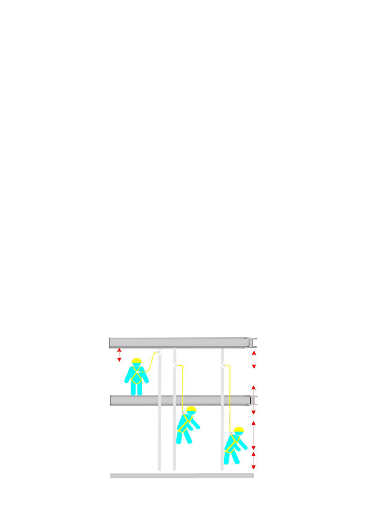
l To minimize falling distance, position the rope grab above the user on the lifeline.
l Rope grabs should be removed from service and discarded once it is subject to a fall.
l After each use, the rope grab should be inspected as mentioned above, then cleaned and stored.
l Avoid exposure to chemical substances or hazards which the fall arrester is not designed to withstand;
failing to do so may result in compromising the material, allowing for the potential of personal injury or
death.
l This product is neither intended for, nor is it suitable for use when the user is positioned on an unstable
surface such as fine grain materials or particulates.
l Users shall not alter the equipment, doing so may result in serious death or injury.
l Care should be taken when using equipment near machines and electrical hazards.
l Contact should be avoided with sharp edges and abrasive surfaces.

8
Instructions of LIFELINE
The Lifeline (1858043-xx) shall be used in combination with the Rope Grab (N-630) and the Energy Absorbing
Lanyard (1858007-ANSI).
1. INTENDED PURPOSE
A lifeline is a component of a complete fall arrest system consisting of a flexible lifeline which is fed through a
rope grab. The rope grab travels along the vertical line which locks into the flexible line when it is subjected
to a fall or travels along the line quickly. The lifeline is also connected to an anchorage point. Any other
components, subsystems or connectors used with this lifeline should be supplied by PALOMA and meet the
applicable ANSI regulations.
2. SIZE
A 5/8 inches (16mm) diameter three-strand lifeline. Rope that is smaller than 5/8 inches diameter may not
allow the rope grab to lock properly and may cause an excessive stopping distance. Rope that is larger than
5/8 inches diameter will reduce mobility.
3. TYPE
It is recommended to use ropes made from polyester fibers as they stretch less due to moisture absorption
than nylon fibers. Ropes made entirely of polypropylene, polyethylene or other olefins are not to be used. It
is not advised to use ropes made from cotton, sisal, hemp, manila or other plant fibers. Kernmantel rope is
not recommended.
4. PERFORMANCE
Breaking strength: 5000 lbf (22.5 kN)
Elongation: 8% Dry / 10% Wet
Melting point: 220 °C
Capacity: 130-310 lbs including equipment
5. WARNING
l Only use one fall arrester be attached to the single anchor lifeline.
l Only one user can be attached to the single anchor lifeline.
l Do not allow lifeline to come in contact with anything that will damage it including: sharp edges,
abrasive surfaces, environmental hazards and chemicals, moving machinery or high-temperature
applications like welding, heat sources, and electrical areas.
l A lifeline may no longer have its rated strength and should be replaced if it is “fluffed” by wear and/or is
discolored to black in the interior of the strands.
l To minimize t he possibili ty of a swing fall, work as directly under the anchorage connector as poss ible.
Striking objects horizontally, due to the pendulum effect, may cause serious injury. Swing falls also
increase the vertical fall distance of a worker, compared to a fall directly below the anchorage connector.
Swing falls may be reduced by using overhead anchorage connectors that move with the worker.
l Only PALOMA, or entities authorized in writing by PALOMA, shall make repairs or alterations to the
equipment.

9
6. INSPECTION
l It is the end-users responsibility to ensure that the anchorage point provides adequate protection to
handle maximum load protection. Anchor points should be capable of supporting 5000 blf (22.5 kN) per
worker and also should be above the worker to avoid a pendulum fall.
l This unit meets ANSI Z359.15-2014 regulations. The user shall understand and adhere to applicable
governing occupational safety standards and/or regulations.
l The arresting distance for the vertical life line shall not exceed 1m.
l The end of the lifeline must have stopper knot to prevent the fall arrester inadvertently traveling off the
lifeline.
l A lifeline should be immediately discarded if the product has been involved in a fall arrest. Additionally,
items which have failed due to excessive wear and tear, damage, or malfunction should be discarded.
l All users or companies should have a developed rescue plan in place and the means to implement such
a plan when using the equipment.
l Misusing the equipment by not following the manufacturer’s instructions may result in serious injury or
death.
l Avoid exposure of this until to chemical substances, such as acids, bases, caustic. Failure to do so may
result in compromising the material and allowing for the potential of personal injury or death.
l The vertical lifeline should be held taut by attaching a 6 to 10 lbs weight or by securing the lifeline from
below to allow for free trailing movement of the rope grab. Job site conditions and trained personnel
should determine the safest method of securing the lifeline.
l Users shall not alter the equipment, doing so may result in serious death or injury.
7. CLEANING & MAINTENANCE
The lifeline should be stored in a cool, dry environment away from direct sunlight. To clean product wipe
down with a damp sponge. The use of a mild soap solution can be used for stubborn dirt and/or debris.
NOTE: Refer to ANSI Z359.15-2014 standards regulating lifelines.
8. CALCULATING TOTAL FALL CLEARANCE DISTANCE
It is important to understand this extension known as the “Deceleration Distance” when calculating the total
fall clearance distance to avoid contact with a lower level.
CONNECTION
2FT (0.61m)
ROPE GRAB DECELERATION
DISTANCE 3.3FT (1.0m)
SHOCK ABSORBER
DECELERATION DISTANCE
4FT (1.22m)
6FT (1.83m) HEIGHT
OF WORKER
3.3FT (1.0m) SAFETY
FACTOR (harness stretch)

10
1. When using a full body harness and a rope grab system, you must add the connector length 2.0ft (0.6m) to
the deceleration distance of rope grab 3.3ft (1.0m) to deceleration distance of energy absorber 4.0ft (1.2m)
to the height of the worker (6ft average height).
2. Add an additional 3.3ft (1.0m) to the total as safety clearance including harness stretch.
3. Total i s 18.6ft (5.66m). This is the estimated height that you must attach your anchorage to reduce the risk
of coming in contact with the lower level. This is the safe fall clearance distance.
4. Arresting distance for the vertical lifeline is not to exceed 3.3 ft (1.0m).
WARNING: Before using the lifeline, calculate your fall distance and select the proper equipment to meet
estimated fall clearance. Failure to select proper equipment and calculate fall distances may result in serious
personal injury, illness or death.
Care should be taken when joining the complete fall arrest system together. The following steps should be
followed:
1. Fit a harness.
2. Attach the snap hook from the lifeline to the anchorage point. (Warning: Ensure anchorage point can
support 5000 lbf).
3. Attach the snap hook from the lanyard/rope grab combo to attachment D-ring of the harness.
4. Unlock rope grab, by unlocking safety and then turning knob counter clockwise until unit opens.
5. With the arrow(s) point towards the anchorage point, insert lifeline.
6. Secure lifeline by closing hinge, turning knob clockwise until securely in place, close safety.
NOTE: To ensure a correct connec tion has been made, it should be noted that the lifeline wil l ONLY travel
towards the anchorage point. To test this move the lanyard back and forth a few inches to ensure a correct
connection. If the lifeline travels in the opposite direction the lifeline may have been position incorrectly into
the rope grab. Disassemble and return to step 5 and follow through until step 6.
9. LABELLING
Label 1,2,3
Label 5
Label 4

11
Label 1
Label 2
Label 3
Label 4
Label 5

12
Checking Card
Equipment Record
Reference
Serial number
Year of manufacture
Date of purchase
Date of first put into operation
User name
Comments
Inspection Log
Date
Reason for entry (periodic
examination or repair)
Competent person name
+ signature
Comments
Next Due date for
periodic
examination
Ningbo Paloma Fall Protection Equipments Co., Ltd
Block 3, No.367 Buzheng East Road, Haishu District, Ningbo City,
Zhejiang-315176, China
Tel: +86-574-87641582
Fax: +86-574-87641584
Web: www.palomasafety.com
This manual suits for next models
1
Table of contents
Popular Safety Equipment manuals by other brands

Lalizas
Lalizas SOLAS manual

ETI Solid State Lighting
ETI Solid State Lighting EM-ELC-R Use and care guide

Clevertronics
Clevertronics LP GIGANTOR 80 METER LED EXIT Installation & maintenance instructions

CMC Rescue
CMC Rescue Pro Series manual

Yoke
Yoke Extreme-100 X-A05-06 Assembly

Vimar
Vimar Plana instruction sheet