manuals.online logo
Brands
  1. Home
  2. •
  3. Brands
  4. •
  5. Panasonic
  6. •
  7. Air Conditioner
  8. •
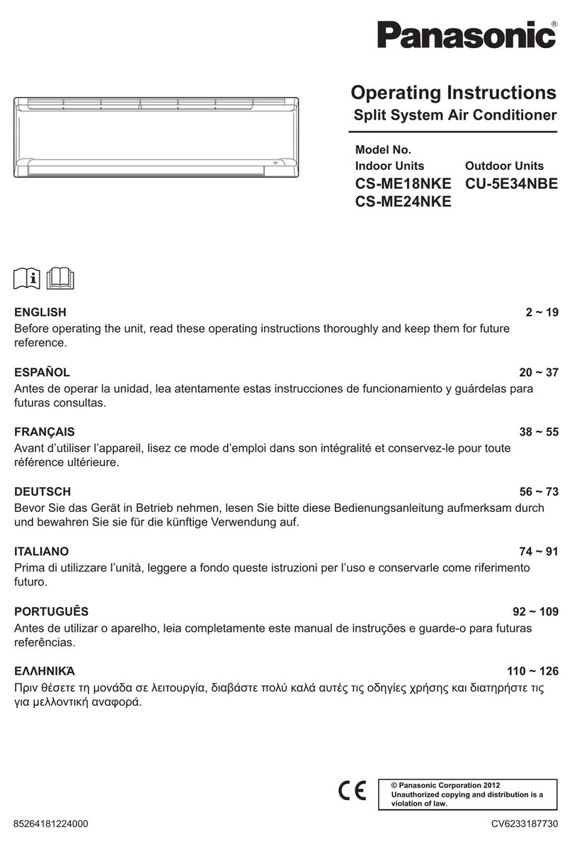
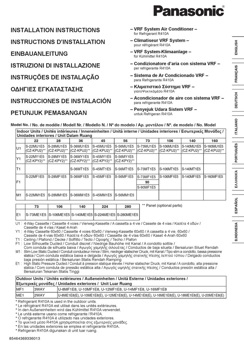
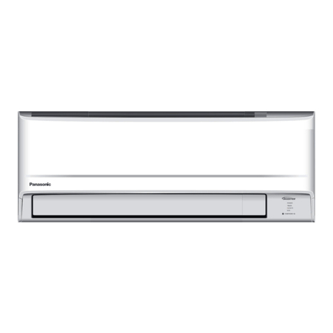
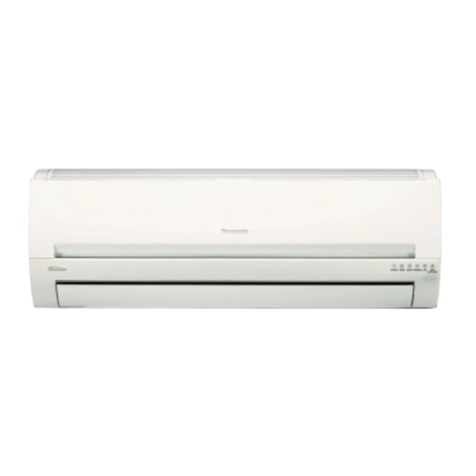
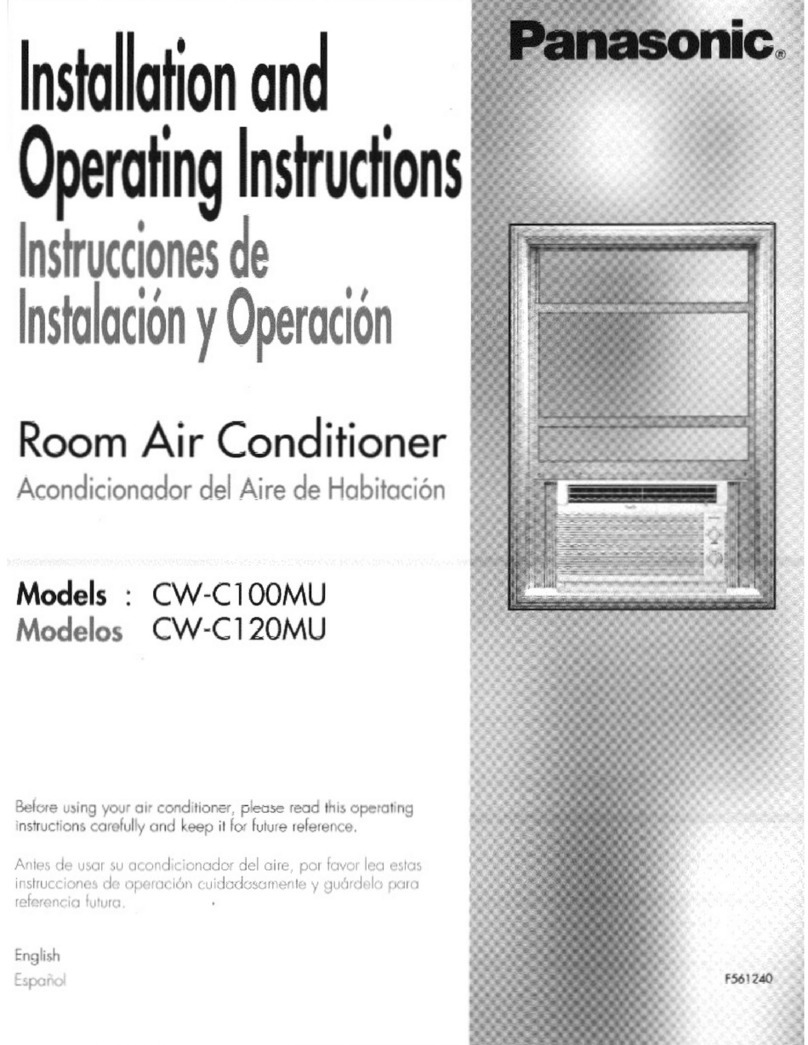
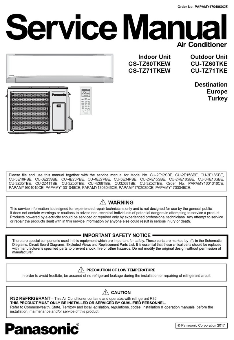
  9. Panasonic S-22MU1E5A Instruction manual

Panasonic S-22MU1E5A Instruction manual

85464869272000 REFERENCE NO.TD831172-00
Indoor Unit
Class 2215 28 36 45 56 60 73 90 106
K1
Wall Mounted
140
T2
Ceiling
160
U1
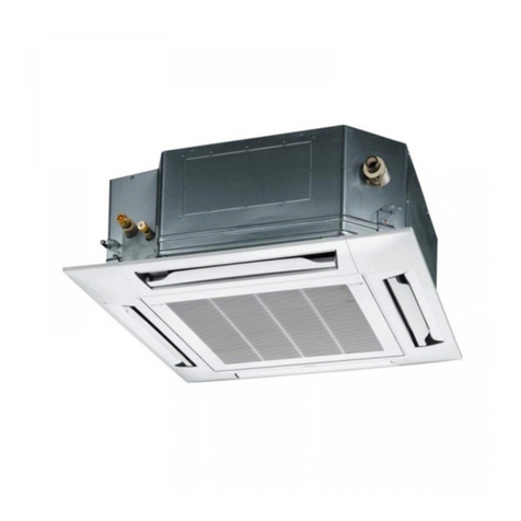
4-Way Cassette
K2
Wall Mounted
Y2
4-Way Cassette
60×60
F2
Low Silhouette
Ducted
S-22MU1E5A
S-22MK2E5AS-15MK2E5A
S-22MY2E5AS-15MY2E5A
S-22MF2E5AS-15MF2E5A
S-28MU1E5A
S-28MK2E5A
S-28MY2E5A
S-28MF2E5A
S-36MT2E5A
S-36MU1E5A
S-36MK2E5A
S-36MY2E5A
S-36MF2E5A
S-45MK1E5A
S-45MT2E5A
S-45MU1E5A
S-45MY2E5A
S-45MF2E5A
S-56MK1E5A
S-56MT2E5A
S-56MU1E5A
S-56MY2E5A
S-56MF2E5A
S-60MU1E5A
S-60MF2E5A
S-73MK1E5A
S-73MT2E5A
S-73MU1E5A
S-73MF2E5A
S-90MU1E5A
S-90MF2E5A
S-106MK1E5A
S-106MT2E5A
S-106MU1E5A
S-106MF2E5A
S-140MT2E5A
S-140MU1E5A
S-140MF2E5A
S-160MU1E5A
S-160MF2E5A
Order No. SBPAC1403010CE
VRF SYSTEMS INDOOR UNIT
4-Way Cassette
(U1 type)
Low Silhouette Ducted
(F2 type)
Ceiling
(T2 type)
TD831172-00VRFSYSINDOOR.indb1TD831172-00VRFSYSINDOOR.indb1 2014/06/1910:37:482014/06/1910:37:48
●Connectable outdoor unit lineup
This document is the Service Manual of the indoor unit.
For outdoor unit, refer to the Service Manual of the outdoor unit.
■For Europe
■For Asia
■For Oceania
Type Outdoor Unit Type 4 hp 5 hp 6 hp 8 hp 10 hp
ME1 2WAY VRF System U-8ME1E81 U-10ME1E81
MF2 3WAY VRF System U-8MF2E8 U-10MF2E8
LE1 Mini VRF System U-4LE1E5 U-5LE1E5 U-6LE1E5
U-4LE1E8 U-5LE1E8 U-6LE1E8
Type Outdoor Unit Type 4 hp 5 hp 6 hp 8 hp 10 hp
ME1 2WAY VRF System U-8ME1H7 U-10ME1H7
U-8ME1H7E* U-10ME1H7E*
LE1 Mini VRF System
U-4LE1H4 U-5LE1H4 U-6LE1H4
U-4LE1H4E* U-5LE1H4E* U-6LE1H4E*
U-4LE1H7 U-5LE1H7 U-6LE1H7
U-4LE1H7E* U-5LE1H7E* U-6LE1H7E*
Type Outdoor Unit Type 4 hp 5 hp 6 hp 8 hp 10 hp
ME1 2WAY VRF System
U-8ME1R8 U-10ME1R8
U-8ME1R8B U-10ME1R8B
U-8ME1R8BE* U-10ME1R8BE*
MF2 3WAY VRF System
U-8MF2R7 U-10MF2R7
U-8MF2R7B U-10MF2R7B
U-8MF2R7BE* U-10MF2R7BE*
LE1 Mini VRF System
U-4LE1R5 U-5LE1R5 U-6LE1R5
U-4LE1R5E* U-5LE1R5E* U-6LE1R5E*
U-4LE1R8 U-5LE1R8 U-6LE1R8
U-4LE1R8E* U-5LE1R8E* U-6LE1R8E*
Type Outdoor Unit Type 12 hp 14 hp 16 hp 18 hp 20 hp
ME1 2WAY VRF System U-12ME1E81 U-14ME1E81 U-16ME1E81 U-18ME1E81 U-20ME1E81
MF2 3WAY VRF System U-12MF2E8 U-14MF2E8 U-16MF2E8
Type Outdoor Unit Type 12 hp 14 hp 16 hp 18 hp 20 hp
ME1 2WAY VRF System U-12ME1H8 U-14ME1H8 U-16ME1H8 U-18ME1H8 U-20ME1H8
U-12ME1H8E* U-14ME1H8E* U-16ME1H8E* U-18ME1H8E* U-20ME1H8E*
* Salt-Air Damage Resistant Specifications.
April 2014
Type Outdoor Unit Type 12 hp 14 hp 16 hp 18 hp 20 hp
ME1 2WAY VRF System
U-12ME1R8 U-14ME1R8 U-16ME1R8 U-18ME1R8 U-20ME1R8
U-12ME1R8B U-14ME1R8B U-16ME1R8B U-18ME1R8B U-20ME1R8B
U-12ME1R8BE* U-14ME1R8BE* U-16ME1R8BE* U-18ME1R8BE* U-20ME1R8BE*
MF2 3WAY VRF System
U-12MF2R8 U-14MF2R8
U-12MF2R8B U-14MF2R8B
U-12MF2R8BE* U-14MF2R8BE*
* Salt-Air Damage Resistant Specifications.
i
SM830232-00欧州向けVRFIndoor201404.indb2 2014/04/1715:03:54
TD831172-00VRFSYSINDOOR.indb2TD831172-00VRFSYSINDOOR.indb2 2014/06/1910:37:582014/06/1910:37:58
2-2
Design of VRF SYSTEM
1
2
3
4
5
6
7
8
9
1. Electrical Wiring
1-1. General Precautions on Wiring
(1)
(2)
(3)
(4)
(5)
(6)
Before wiring, confirm the rated voltage of the unit as shown
on its nameplate, then carry out the wiring closely following
the wiring diagram.
Provide a power outlet to be used exclusively for each
unit, and a power supply disconnect, circuit breaker and
earth leakage breaker for overcurrent protection should be
provided in the exclusive line.
To prevent possible hazards from insulation failure, the unit
must be grounded.
Each wiring connection must be done in accordance with
the wiring system diagram. Wrong wiring may cause the
unit to misoperate or become damaged.
Do not allow wiring to touch the refrigerant tubing,
compressor, or any moving parts of the fan.
Unauthorized changes in the internal wiring can be very
dangerous. The manufacturer will accept no responsibility
for any damage or misoperation that occurs as a result of
such unauthorized changes.
(7)
(8)
The remote control wiring and the inter-unit control wiring
should be wired apart from the inter-unit power wiring.
Use shielded wires for inter-unit control wiring between
units and ground the shield on both sides.
(9)
1-2. Recommended Wire Length and Wire Diameter for Power Supply System
Control wiring
(C) Inter-unit control wiring
(between outdoor and indoor units)
0.75 mm² (AWG #18)
Use shielded wiring*
Max. 1,000 m
(D) Remote control wiring
0.75 mm² (AWG #18)
Max. 500 m
NOTE * With ring-type wire terminal.
(E) Control wiring for group control
0.75 mm² (AWG #18)
Max. 200 m (Total)
(10)
Regulations on wire diameters differ from locality to
locality. For field wiring rules, please refer to your LOCAL
ELECTRICAL CODES before beginning. You must
ensure that installation complies with all relevant rules and
regulations.
To prevent malfunction of the air conditioner caused by
electrical noise, care must be taken when wiring as follows:
If the power supply cord of this appliance is damaged,
it must be replaced by a repair shop appointed by the
manufacturer, because special purpose tools are required.
Use a waterproof conduit for outdoor unit wiring to avoid
damaging the wire and to prevent accumulation of liquid
inside the unit.
Indoor unit
Type (B) Power supply Time delay fuse or
circuit capacity
2.5 mm²Minimum 2 mm²
Max. 150 m
Max. 130 m
Max. 150 m 10 – 16 A
15 A
15 A
K1
K2
Y2
U1 10 – 16 A
Max. 130 m
F2 10 – 16 A
Max. 130 m
T2 10 – 16 A
Max. 130 m
TDxxxxxx-002WAYVRF.indb2TDxxxxxx-002WAYVRF.indb2 2014/01/3017:52:302014/01/3017:52:30
2-3
Design of VRF SYSTEM
1
2
3
4
5
6
7
8
9
1. Electrical Wiring
1-3. Wiring System Diagrams
(1) Refer to Section 1-2. “Recommended Wire Length and
Wire Diameter for Power Supply System” for the
explanation of “B”, “C”, “D” and “E” in the above
diagram.
(2) The basic connection diagram of the indoor unit shows
the 7P terminal board, so the terminal boards in your
equipment may differ from the diagram.
(3) Refrigerant Circuit (R.C.) address should be set before
turning the power on.
(4) Address setting can be executed by remote controller
automatically. Refer to Section 5.
U2
U1
R2
R1
L
N
R2
R1
R2
R1
R2
R1
2
1
2
1
U2
U1
L
N
U2
U1
L
N
U2
U1
L
N
2
1
2
1
2
1
D
E
C
B
L
N
L
N
L
N
L
N
2
1
B
B
B
C
D
D
C
C
Power supply
220/230/240V ~50/60Hz
Remote
controller
Remote
controller
Remote
controller
WHT
BLK
WHT
BLK
WHT
BLK
Power supply
220/230/240V ~50/60Hz
Power supply
220/230/240V ~50/60Hz
Power supply
220/230/240V ~50/60Hz
Ground
Ground
Ground
Ground
Ground
Ground
To outdoor unit
Outdoor unit
Ground
Ground
Ground
Ground
Ground
Indoor unit
(No. 1)
Indoor unit
(No. 2)
Indoor unit
(No. n)
Indoor unit
(No. 3)
Group control:
LN U1U2
5P terminal board
Power
supply
K1 Type
K2 Type
Unit
control
line
L N U1 U2 R1 R2
LNU1 U2 R1 R2
6P terminal board
Power
supply
Unit
control
line
Remote
control
line
U1 Type
6P terminal board
F2 Type
Power
supply
Remote
control
line
Unit
control
line
6P terminal board
Power
supply
cable
Inter-unit
control
wiring
Remote
control
wiring
Y2 Type
Terminal Board
Power supply
cable
Inter-unit con-
trol wiring
Inter-unit con-
trol wiring
Fig. 2-1
L N U1 U2 R1 R2
6P terminal board
T2 Type
Power
supply
Remote
control
line
Unit
control
line
TDxxxxxx-002WAYVRF.indb3TDxxxxxx-002WAYVRF.indb3 2014/01/3017:52:302014/01/3017:52:30
2-4
Design of VRF SYSTEM
1
2
3
4
5
6
7
8
9
1. Electrical Wiring
(1)
(2)
When linking the outdoor units in a network, disconnect the terminal extended from the short plug from
all outdoor units except any one of the outdoor units.
(When shipping: In shorted condition.)
For a system without link (no wiring connection between outdoor units), do not remove the short plug.
Do not install the inter-unit control wiring in a way that forms a loop.
Outdoor unit
Indoor unit
Indoor unit
Indoor unit
Indoor unit
NO
Branch point
Outdoor unit Outdoor unit Outdoor unit
Prohibited
Prohibited
Indoor unit
Indoor unit
Indoor unit Indoor unit Indoor unit
CAUTION
(3) Do not install inter-unit control wiring such as star branch wiring. Star branch wiring causes mis-address
setting.
(4) If branching the inter-unit control wiring, the number of branch points should be 16 or fewer.
Fig. 2-2
Fig. 2-3
Fig. 2-4
Central Controller
Outdoor unit
Outdoor unit
Outdoor unit
Indoor unit Indoor unit Indoor unit
Indoor unit Indoor unit
Indoor unit
Indoor unit
: Branch point
More than 2m required
TDxxxxxx-002WAYVRF.indb4TDxxxxxx-002WAYVRF.indb4 2014/01/3017:52:302014/01/3017:52:30
2-5
Design of VRF SYSTEM
1
2
3
4
5
6
7
8
9
1. Electrical Wiring
Shielded wire
Ground Ground
Screw and
Special washer
Ring
pressure
terminal
Terminal board
Ring pressure
terminal
Screw
Special
washer
Wire
Wire
Insulation tape
8mm
Insulation tape
Shield mesh
Shield mesh
Fig. 2-5
Stranded wire
Ring
pressure
terminal
Strip 10 mm
Fig. 2-6
Fig. 2-7
Fig. 2-8
Fig. 2-9
Fig. 2-10
Fig. 2-11
(5)
Use shielded wires for inter-unit control wiring (c) and
ground the shield on both sides, otherwise misoperation
from noise may occur. (Fig. 2-5)
Connect wiring as shown in Section “1-3. Wiring System
Diagrams”.
(6) Connecting cable between indoor unit and outdoor unit shall be approved polychloroprene sheathed
5 or 3 *1.5 mm2flexible cord. Type designation 60245 IEC 57 (H05RN-F, GP85PCP etc.) or heavier
cord.
WARNING
Loose wiring may cause the terminal to overheat or result in unit malfunction.
A fire hazard may also occur.
Therefore, ensure that all wiring is tightly connected.
When connecting each power wire to the terminal, follow the instructions on “How to connect wiring to the terminal”
and fasten the wire securely with the fixing screw of the terminal board.
How to connect wiring to the terminal
For stranded wiring
(1)
then strip the insulation to expose
the stranded wiring about 10 mm and
tightly twist the wire ends. (Fig. 2-6)
(2)
remove the terminal screw(s) on the
terminal board.
(3)
pliers, securely clamp each stripped
wire end with a ring pressure terminal.
(4)
Cut the wire end with cutting pliers,
Using a Phillips head screwdriver,
Using a ring connector fastener or
Place the ring pressure terminal,
and replace and tighten the removed
terminal screw using a screwdriver.
(Fig. 2-7)
Examples of shield wires
(1)
(2)
together.
Coat with insulation tube or wrap insulation tape after
putting tightly. (Fig. 2-9)
(3)
(4)
Remove cable coat not to scratch braided shield. (Fig. 2-8)
Ravel braided shield carefully and put tightly braided shield
Remove coat of signal wire. (Fig. 2-10)
Connect signal wire removed coat and shield wire with
pressure terminal. (Fig. 2-11)
Earth wire for power supply
The earth wire should be longer than the other lead wires for
electrical safety.
Use the standard power supply cables for Europe (such as H05RN-F or H07RN-F which conform to
CENELEC (HAR) rating specifications) or use the cables based on IEC standard. (60245 IEC57, 60245
IEC66)
TDxxxxxx-002WAYVRF.indb5TDxxxxxx-002WAYVRF.indb5 2014/01/3017:52:302014/01/3017:52:30
2-8
Design of VRF SYSTEM
1
2
3
4
5
6
7
8
9
1. Electrical Wiring
Wiring sample
K2 Type
K1 Type
L1 L2 N U1 U2
R1 R2
Remote Control Wiring
Inter-unit Control Wiring
Power Supply
Power Supply
Resin cover
Fixture screw for resin cover
* As to functional ground screw and protective ground screw, remove the fixture screw and resin cover.
Then, carry out earth ground work.
Functional ground screw (External Electronic
Expansion Valve Kit and Schedule Timer) *
Protective ground screw
(External Solenoid Valve Kit for 3WAY) *
Protective ground screw
(External Solenoid Valve Kit for 3WAY)
Use this screw when connecting to ground
the shield for the Inter-unit control wiring.
Functional ground screw (Schedule Timer)
Remote Control Wiring
Use this screw when connecting the shield
for the Inter-unit control wiring to ground.
Inter-unit Control Wiring
TDxxxxxx-002WAYVRF.indb8TDxxxxxx-002WAYVRF.indb8 2014/01/3017:52:302014/01/3017:52:30
4-1
VRF SYSTEMS Indoor Unit Specifications
1
2
3
4
5
6
7
8
9
Contents
4. VRF SYSTEMS INDOOR UNIT SPECIFICATIONS
1. 4-Way Cassette Type (U1 Type) .........................................................................................
1-1. Specifications .................................................................................................................4-2
4-6
4-17
4-20
4-22
4-25
4-29
4-41
4-43
4-45
4-49
4-51
4-57
4-58
4-60
4-2
4-25
4-49
4-63
4-65
4-69
4-70
4-71
4-63
1-2. Major Component Specifications....................................................................................
1-3. Dimensional Data ........................................................................................................
1-4. Noise Criterion Curves ................................................................................................
1-5. Air Flow Distance / Temperature Chart .......................................................................
2. Low Silhouette Ducted Type (F2 Type) ...........................................................................
2-1. Specifications ...............................................................................................................
2-2. Major Component Specifications..................................................................................
2-3. Dimensional Data ........................................................................................................
2-4. Noise Criterion Curves ................................................................................................
2-5. External Static Pressure Setting ..................................................................................
3. 4-Way Cassette 60×60 Type (Y2 Type) ............................................................................
3-1. Specifications ...............................................................................................................
3-2. Major Component Specifications..................................................................................
3-3. Dimensional Data ........................................................................................................
3-4. Noise Criterion Curves ................................................................................................
3-5. Air Flow Distance / Temperature Chart .......................................................................
4. Wall Mounted Type (K2 Type) ..........................................................................................
4-1. Specifications ..............................................................................................................
4-2. Major Component Specifications..................................................................................
4-3. Dimensional Data ........................................................................................................
4-4. Noise Criterion Curves ................................................................................................
4-5. Air Flow Distance / Temperature Chart .......................................................................
4-73
4-77
4-81
4-82
4-83
4-735. Wall Mounted Type (K1 Type) ..........................................................................................
5-1. Specifications ...............................................................................................................
5-2. Major Component Specifications..................................................................................
5-3. Dimensional Data ........................................................................................................
5-4. Noise Criterion Curves ................................................................................................
5-5. Air Flow Distance / Temperature Chart .......................................................................
4-85
4-87
4-93
4-94
4-95
4-85
4-98
6. Ceiling Type (T2 Type) ......................................................................................................
6-1. Specifications ..............................................................................................................
6-2. Major Component Specifications..................................................................................
4-98
4-99
7-1. Precautions Regarding External Air Intake .................................................................
7-2. External Air Intake Volume & Resistance Within Unit /
Operation Noise Characteristics.........................
6-3. Dimensional Data ........................................................................................................
6-4. Noise Criterion Curves ................................................................................................
6-5. Air Flow Distance / Temperature Chart .......................................................................
7. Fresh Air Intake ................................................................................................................
4-Way Cassette (U1 Type)
Ceiling (T2 Type)
Low Silhouette Ducted (F2 Type)
4-Way Cassette 60×60 (Y2 Type)
TD831172-00VRFSYSINDOOR.indb1TD831172-00VRFSYSINDOOR.indb1 2014/04/2416:48:422014/04/2416:48:42
4-73
VRF SYSTEMS Indoor Unit Specifications
1
2
3
4
5
6
7
8
9
5. Wall Mounted Type (K1 Type)
Unit specifications (A)
MODEL No. Indoor Unit S-45MK1E5A
POWER SOURCE 220 - 230 - 240 V, single-phase, 50/60 Hz
PERFORMANCE TEST CONDITION ISO15042 / AS / NZS3823 / EN14511 / EN12102
PERFORMANCE Cooling Heating
Capacity kW 4.5 5.0
BTU / h 15,000 17,000
Air circulation (Hi / Me / Lo) m3/ h 720 / 630 / 510
Moisture removal (High) Liters / h 1.6 –
ELECTRICAL RATINGS
Voltage rating V 220 230 240 220 230 240
Available voltage range V 198 - 264 198 - 264
Running amperes A 0.27 0.26 0.23 0.27 0.26 0.23
20 20 21 20 20 21
34 33 38 34 33 38
1111 1 1
Power input W
Power factor %
Max. starting amperes A
FEATURES
Controls Microprocessor
Timer ON / OFF Timer (Max. 72 h)
Fan speeds 3 and Automatic control
Air filter Washable, easy access
Refrigerant control Electronic expansion valve
Operation sound (
Hi / Me / Lo
) dB-A 38 / 34 / 30
Refrigerant tubing connections Flare type
Refrigerant tube
diameter
Liquid tube mm (in.) 6.35 (1 / 4)
Gas tube mm (in.) 12.7 (1 / 2)
Drain connection 13 A, OD18 mm
Remote controller Optional (Wired / Wireless)
Refrigerant tubing kit / Accessories Optional / Hanging wall bracket
Color (Approximate value) Munsell N9.1
DIMENSIONS & WEIGHT
Unit dimensions
Package dimensions
Unit dimensions
Height mm (in.) 300 (11-13 / 16) 310 (12-7 / 32)
Width mm (in.) 1065 (41-15 / 16) 1140 (44-7 / 8)
Depth mm (in.) 230 (9-1 / 16) 380 (14-31 / 32)
Net weight kg(lbs.) 13 (29)
Shipping weight kg(lbs.) 17 (38)
Shipping volume m3(cu.ft) 0.13 (4.6)
DATA SUBJECT TO CHANGE WITHOUT NOTICE.
Rated conditions
Cooling: Indoor air temperature 27°C DB / 19°C WB; Outdoor air temperature 35°C DB
Heating: Indoor air temperature 20°C DB; Outdoor air temperature 7°C DB / 6°C WB
5-1. Specifications
TD831172-00VRFSYSINDOOR.indb73TD831172-00VRFSYSINDOOR.indb73 2014/04/2416:49:272014/04/2416:49:27
4-74
VRF SYSTEMS Indoor Unit Specifications
1
2
3
4
5
6
7
8
9
5. Wall Mounted Type (K1 Type)
Unit specifications (B)
MODEL No. Indoor Unit S-56MK1E5A
POWER SOURCE 220 - 230 - 240 V, single-phase, 50/60 Hz
PERFORMANCE Cooling Heating
Capacity kW 5.6 6.3
BTU / h 19,000 21,000
Air circulation (Hi / Me / Lo) m3/ h 840 / 720 / 630
Moisture removal (High) Liters / h 2.3 –
ELECTRICAL RATINGS
Voltage rating V 220 230 240 220 230 240
Available voltage range V 198 - 264 198 - 264
Running amperes A
Power input W
Power factor %
Max. starting amperes A
FEATURES
Controls Microprocessor
Timer ON / OFF Timer (Max. 72 h)
Fan speeds 3 and Automatic control
Air filter Washable, easy access
Refrigerant control Electronic expansion valve
Operation sound (
Hi / Me / Lo
) dB-A 40 / 36 / 32
Refrigerant tubing connections Flare type
Refrigerant tube
diameter
Liquid tube mm (in.) 6.35 (1 / 4)
Gas tube mm (in.) 12.7 (1 / 2)
Drain connection 13 A, OD18 mm
Remote controller Optional (Wired / Wireless)
Refrigerant tubing kit / Accessories Optional / Hanging wall bracket
Color (Approximate value)
DIMENSIONS & WEIGHT
Unit dimensions
Package dimensions
Unit dimensions
Height mm (in.) 300 (11-13 / 16) 310 (12-7 / 32)
Width mm (in.) 1065 (41-15 / 16) 1140 (44-7 / 8)
Depth mm (in.) 230 (9-1 / 16) 380 (14-31 / 32)
Net weight kg(lbs.) 13 (29)
Shipping weight kg(lbs.) 17 (38)
Shipping volume m3(cu.ft) 0.13 (4.6)
DATA SUBJECT TO CHANGE WITHOUT NOTICE.
Rated conditions
Cooling: Indoor air temperature 27°C DB / 19°C WB; Outdoor air temperature 35°C DB
Heating: Indoor air temperature 20°C DB; Outdoor air temperature 7°C DB / 6°C WB
0.36 0.35 0.32 0.36 0.35 0.32
29 30 30 29 30 30
37 37 39 37 37 39
1111 1 1
Munsell N9.1
PERFORMANCE TEST CONDITION ISO15042 / AS / NZS3823 / EN14511 / EN12102
TD831172-00VRFSYSINDOOR.indb74TD831172-00VRFSYSINDOOR.indb74 2014/04/2416:49:272014/04/2416:49:27
4-75
VRF SYSTEMS Indoor Unit Specifications
1
2
3
4
5
6
7
8
9
5. Wall Mounted Type (K1 Type)
Munsell N9.1
Unit specifications (C)
MODEL No. Indoor Unit S-73MK1E5A
POWER SOURCE 220 - 230 - 240 V, single-phase, 50/60 Hz
PERFORMANCE Cooling Heating
Capacity kW 7.3 8.0
BTU / h 25,000 27,000
Air circulation (Hi / Me / Lo) m3/ h 1080 / 870 / 690
Moisture removal (High) Liters / h 3.0 –
ELECTRICAL RATINGS
Voltage rating V 220 230 240 220 230 240
Available voltage range V 198 - 264 198 - 264
Running amperes A
Power input W
Power factor %
Max. starting amperes A
FEATURES
Controls Microprocessor
Timer ON / OFF Timer (Max. 72 h)
Fan speeds 3 and Automatic control
Air filter Washable, easy access
Refrigerant control Electronic expansion valve
Operation sound (
Hi / Me / Lo
) dB-A 47 / 44 / 40
Refrigerant tubing connections Flare type
Refrigerant tube
diameter
Liquid tube mm (in.) 9.52 (3 / 8)
Gas tube mm (in.) 15.88 (5 / 8)
Drain connection 13 A, OD18 mm
Remote controller Optional (Wired / Wireless)
Refrigerant tubing kit / Accessories Optional / Hanging wall bracket
Color (Approximate value)
DIMENSIONS & WEIGHT
Unit dimensions
Package dimensions
Unit dimensions
Height mm (in.) 300 (11-13 / 16) 310 (12-7 / 32)
Width mm (in.) 1065 (41-15 / 16) 1140 (44-7 / 8)
Depth mm (in.) 230 (9-1 / 16) 380 (14-31 / 32)
Net weight kg(lbs.) 14.5 (32)
Shipping weight kg(lbs.) 18 (40)
Shipping volume m3(cu.ft) 0.13 (4.6)
DATA SUBJECT TO CHANGE WITHOUT NOTICE.
Rated conditions
Cooling: Indoor air temperature 27°C DB / 19°C WB; Outdoor air temperature 35°C DB
Heating: Indoor air temperature 20°C DB; Outdoor air temperature 7°C DB / 6°C WB
0.59 0.58 0.52 0.59 0.58 0.52
56 57 57 56 57 57
43 43 46 43 43 46
1111 1 1
PERFORMANCE TEST CONDITION ISO15042 / AS / NZS3823 / EN14511 / EN12102
TD831172-00VRFSYSINDOOR.indb75TD831172-00VRFSYSINDOOR.indb75 2014/04/2416:49:272014/04/2416:49:27
4-76
VRF SYSTEMS Indoor Unit Specifications
1
2
3
4
5
6
7
8
9
5. Wall Mounted Type (K1 Type)
Unit specifications (D)
MODEL No. Indoor Unit S-106MK1E5A
POWER SOURCE 220 - 230 - 240 V, single-phase, 50/60 Hz
PERFORMANCE Cooling Heating
Capacity kW 10.6 11.4
BTU / h 36,000 39,000
Air circulation (Hi / Me / Lo) m3/ h 1140 / 990 / 780
Moisture removal (High) Liters / h 4.9 –
ELECTRICAL RATINGS
Voltage rating V 220 230 240 220 230 240
Available voltage range V 198 - 264 198 - 264
Running amperes A
Power input W
Power factor %
Max. starting amperes A
FEATURES
Controls Microprocessor
Timer ON / OFF Timer (Max. 72 h)
Fan speeds 3 and Automatic control
Air filter Washable, easy access
Refrigerant control Electronic expansion valve
Operation sound (
Hi / Me / Lo
) dB-A 49 / 45 / 42
Refrigerant tubing connections Flare type
Refrigerant tube
diameter
Liquid tube mm (in.) 9.52 (3 / 8)
Gas tube mm (in.) 15.88 (5 / 8)
Drain connection 13 A, OD18 mm
Remote controller Optional (Wired / Wireless)
Refrigerant tubing kit / Accessories Optional / Hanging wall bracket
Color (Approximate value)
DIMENSIONS & WEIGHT
Unit dimensions
Package dimensions
Unit dimensions
Height mm (in.) 300 (11-13 / 16) 310 (12-7 / 32)
Width mm (in.) 1065 (41-15/ 16) 1140 (44-7 / 8)
Depth mm (in.) 230 (9-1 / 16) 380 (14-31 / 32)
Net weight kg(lbs.) 14.5 (32)
Shipping weight kg(lbs.) 18 (40)
Shipping volume m3(cu.ft) 0.13 (4.6)
DATA SUBJECT TO CHANGE WITHOUT NOTICE.
Rated conditions
Cooling: Indoor air temperature 27°C DB / 19°C WB; Outdoor air temperature 35°C DB
Heating: Indoor air temperature 20°C DB; Outdoor air temperature 7°C DB / 6°C WB
0.63 0.62 0.55 0.70 0.70 0.62
59 60 60 67 68 68
43 42 45 44 42 46
1111 1 1
Munsell N9.1
PERFORMANCE TEST CONDITION ISO15042 / AS / NZS3823 / EN14511 / EN12102
TD831172-00VRFSYSINDOOR.indb76TD831172-00VRFSYSINDOOR.indb76 2014/04/2416:49:272014/04/2416:49:27
4-77
VRF SYSTEMS Indoor Unit Specifications
1
2
3
4
5
6
7
8
9
5. Wall Mounted Type (K1 Type)
5-2. Major Component Specifications
Indoor unit (A)
MODEL No. S-45MK1E5A
Power source 220 - 230 - 240 V, single-phase, 50/60 Hz
Controller P.C.B. Ass'y CR-K186XH (Microprocessor)
Fan (Number...diameter) mm Cross-flow ø100 / L838
Fan motor
Model...Nominal output W SIC-39CVL-D847-10...47 W
Power source 220 - 230 - 240 V / single-phase / 50 Hz
No. of pole...r.p.m. (230V, High) rpm 8P... 1,650
Electronic expansion valve
Coil UKV-A052
Coil resistance (at 20°C) ΩORG – GRY : 46 YEL – GRY : 46
RED – GRY : 46 BLK – GRY : 46
Valve body UKV-25D32
Heat exchanger
Coil Aluminium plate fin / Copper tube
Rows...fin pitch mm 2...1.3
Face area m20.325
TD831172-00VRFSYSINDOOR.indb77TD831172-00VRFSYSINDOOR.indb77 2014/04/2416:49:282014/04/2416:49:28
4-78
VRF SYSTEMS Indoor Unit Specifications
1
2
3
4
5
6
7
8
9
5. Wall Mounted Type (K1 Type)
Indoor unit (B)
MODEL No. S-56MK1E5A
Power source 220 - 230 - 240 V, single-phase, 50/60 Hz
Controller P.C.B. Ass'y
Fan (Number...diameter) mm Cross-flow ø100 / L838
Fan motor
Model...Nominal output W SIC-39CVL-D847-10...47 W
Power source 220 - 230 - 240 V / single-phase / 50 Hz
No. of pole...r.p.m. (230V, High) rpm 8P... 1,650
Electronic expansion valve
Coil UKV-A052
Coil resistance (at 20°C) ΩORG – GRY : 46 YEL – GRY : 46
RED – GRY : 46 BLK – GRY : 46
Valve body UKV-25D32
Heat exchanger
Coil Aluminium plate fin / Copper tube
Rows...fin pitch mm 2...1.3
Face area m20.325
CR-K186XH (Microprocessor)
TD831172-00VRFSYSINDOOR.indb78TD831172-00VRFSYSINDOOR.indb78 2014/04/2416:49:282014/04/2416:49:28
4-79
VRF SYSTEMS Indoor Unit Specifications
1
2
3
4
5
6
7
8
9
5. Wall Mounted Type (K1 Type)
Indoor unit (C)
MODEL No. S-73MK1E5A
Power source 220 - 230 - 240 V, single-phase, 50/60 Hz
Controller P.C.B. Ass'y
Fan (Number...diameter) mm Cross-flow ø100 / L838
Fan motor
Model...Nominal output W SIC-39CVL-D847-10...47 W
Power source 220 - 230 - 240 V / single-phase / 50 Hz
No. of pole...r.p.m. (230V, High) rpm 8P... 1,650
Electronic expansion valve
Coil UKV-A052
Coil resistance (at 20°C) ΩORG – GRY : 46 YEL – GRY : 46
RED – GRY : 46 BLK – GRY : 46
Valve body UKV-25D32
Heat exchanger
Coil Aluminium plate fin / Copper tube
Rows...fin pitch mm 2+1...1.3
Face area m20.334
CR-K186XH (Microprocessor)
TD831172-00VRFSYSINDOOR.indb79TD831172-00VRFSYSINDOOR.indb79 2014/04/2416:49:282014/04/2416:49:28
4-80
VRF SYSTEMS Indoor Unit Specifications
1
2
3
4
5
6
7
8
9
5. Wall Mounted Type (K1 Type)
Indoor unit (D)
MODEL No. S-106MK1E5A
Power source 220 - 230 - 240 V, single-phase, 50/60 Hz
Controller P.C.B. Ass'y
Fan (Number...diameter) mm Cross-flow ø100 / L838
Fan motor
Model...Nominal output W SIC-39CVL-D847-10...47 W
Power source 220 - 230 - 240 V / single-phase / 50 Hz
No. of pole...r.p.m. (230V, High) rpm 8P... 1,650
Electronic expansion valve
Coil UKV-A052
Coil resistance (at 20°C) ΩORG – GRY : 46 YEL – GRY : 46
RED – GRY : 46 BLK – GRY : 46
Valve body UKV-25D32
Heat exchanger
Coil Aluminium plate fin / Copper tube
Rows...fin pitch mm 2+1...1.3
Face area m20.334
CR-K186XH (Microprocessor)
TD831172-00VRFSYSINDOOR.indb80TD831172-00VRFSYSINDOOR.indb80 2014/04/2416:49:282014/04/2416:49:28
4-81
VRF SYSTEMS Indoor Unit Specifications
1
2
3
4
5
6
7
8
9
5. Wall Mounted Type (K1 Type)
5-3. Dimensional Data
Indoor unit: S-45MK1E5A / 56MK1E5A / 73MK1E5A / 106MK1E5A
1065
230 (2.5) 197.4
140
158 415
439.8
496.8
415
448.2
568.2
132
95 95 200
384.3 450
68
300
48
(Ø80)
17.9
37.3
48
230.7
148.7
60
870
115.9
115.9
300
11 67
60
86
67
(Ø80)
Wall Mounted Type
Front view
50 50
75
A
A
B
B
C
C
Refrigerant tubing (liquid tube) 45-56 type 6.35 (flared)
Drain hose VP13 (outer dia. 18)
D
D
Rear panel (PL BACK)
Refrigerant tubing (gas tube)
E
E
73-106 type 9.52 (flared)
45-56 type 12.7 (flared)
73-106 type 15.88 (flared)
Tubing and wiring holes ( 80)
unit: mm
TD831172-00VRFSYSINDOOR.indb81TD831172-00VRFSYSINDOOR.indb81 2014/04/2416:49:282014/04/2416:49:28
4-82
VRF SYSTEMS Indoor Unit Specifications
1
2
3
4
5
6
7
8
9
5. Wall Mounted Type (K1 Type)
5-4. Noise Criterion Curves
S-73MK1E5A
47 dB(A)
LOW
HIGH
40 dB(A)
44 dB(A)
S-106MK1E5A
49 dB(A)
LOW
HIGH
42 dB(A)
45 dB(A)
4000 800025012563 20001000500
60
50
40
30
20
10
STRONG
Frequency at center of sound pressure band (Hz)
Overall
NC-20
NC-30
NC-40
NC-50
60
50
40
30
10
20
Approximate
minimum audible
limit for
continuous noise
4000 800025012563 20001000500
Overall
Frequency at center of sound pressure band (Hz)
NC-20
NC-30
NC-40
NC-50
Approximate
minimum audible
limit for
continuous noise
STRONG
Sound pressure level (dB)
(0dB = 0.0002 bar)
Sound pressure level (dB)
(0dB = 0.0002 bar)
MODEL
SOUND
LEVEL
:
:
CONDITION :
1m in front of air discharge and then 1m below
MODEL
SOUND
LEVEL
:
:
CONDITION :
1m in front of air discharge and then 1m below
MODEL
S-45MK1E5A S-56MK1E5A
SOUND
LEVEL
38 dB(A)
LOW
HIGH
30 dB(A)
34 dB(A)
NC-20
NC-30
NC-40
NC-50
60
50
40
30
10
20
Approximate
minimum audible
limit for
continuous noise
4000 800025012563 20001000500
Overall
Frequency at center of sound pressure band (Hz)
STRONG
Sound pressure level (dB)
(0dB = 0.0002 bar)
40 dB(A)
LOW
HIGH
32 dB(A)
36 dB(A)
4000 800025012563 20001000500
60
50
40
30
20
10
STRONG
Frequency at center of sound pressure band (Hz)
Overall
NC-20
NC-30
NC-40
NC-50
Approximate
minimum audible
limit for
continuous noise
Sound pressure level (dB)
(0dB = 0.0002 bar)
Both 50Hz and 60Hz
Strong
Weak
:
:
:
CONDITION :
1m in front of air discharge and then 1m below
MODEL
SOUND
LEVEL
:
:
CONDITION :
1m in front of air discharge and then 1m below
TD831172-00VRFSYSINDOOR.indb82TD831172-00VRFSYSINDOOR.indb82 2014/04/2416:49:282014/04/2416:49:28
4-83
VRF SYSTEMS Indoor Unit Specifications
1
2
3
4
5
6
7
8
9
5. Wall Mounted Type (K1 Type)
5-5. Air Flow Distance / Temperature Chart
012345 012345
012345 012345
012345 012345
012345 012345
1
0
2
3
1
0
2
3
1.5m/s
1.2m/s0.9m/s
0.3m/s
0.6m/s
0.3m/s
33
27 24
30
1
0
2
3
1
0
2
3
1.5m/s 1.2m/s
0.9m/s
0.3m/s
0.6m/s
0.6m/s
0.3m/s 20
24
26
26
22
Heating : Distribution of wind velocity Heating : Distribution of temperature
Cooling : Distribution of wind velocity Cooling : Distribution of temperature
Vertical air flow distance (m)
Horizontal air flow distance (m)Horizontal air flow distance (m)
S-45MK1E5A
S-56MK1E5A
(Strong wind :
Discharge angle app.60°) (Rm. temp.app.20°C) (Strong wind :
Discharge angle app.60°) (Rm. temp.app.20°C)
(Strong wind :
Discharge angle app.30°) (Rm. temp.app.27°C) (Strong wind :
Discharge angle app.30°) (Rm. temp.app.27°C)
1
0
2
3
1
0
2
3
1.5m/s
1.2m/s0.9m/s
0.3m/s
0.6m/s
0.3m/s
33
27 24
30
1
0
2
3
1
0
2
3
1.5m/s 1.2m/s
0.9m/s
0.3m/s
0.6m/s
0.6m/s
0.3m/s 20
24
26
26
22
Heating : Distribution of wind velocity Heating : Distribution of temperature
Vertical air flow distance (m)
(Strong wind :
Discharge angle app.60°) (Rm. temp.app.20°C) (Strong wind :
Discharge angle app.60°) (Rm. temp.app.20°C)
(Strong wind :
Discharge angle app.30°) (Rm. temp.app.27°C) (Strong wind :
Discharge angle app.30°) (Rm. temp.app.27°C)
TD831172-00VRFSYSINDOOR.indb83TD831172-00VRFSYSINDOOR.indb83 2014/04/2416:49:282014/04/2416:49:28
4-84
VRF SYSTEMS Indoor Unit Specifications
1
2
3
4
5
6
7
8
9
5. Wall Mounted Type (K1 Type)
1
0
2
3
1
0
2
3
1.5m/s
1.2m/s 0.9m/s 0.3m/s
0.6m/s
0.3m/s
33
27 24
30
1
0
2
3
1
0
2
3
1.5m/s
1.2m/s
0.9m/s
0.9m/s
0.3m/s
0.6m/s
0.6m/s
0.3m/s 20
24
26
26
22
S-73MK1E5A
Heating : Distribution of wind velocity Heating : Distribution of temperature
Vertical air flow distance (m)Vertical air flow distance (m)
Vertical air flow distance (m)
(Strong wind :
Discharge angle app.60°) (Rm. temp.app.20°C) (Strong wind :
Discharge angle app.60°) (Rm. temp.app.20°C)
(Strong wind :
Discharge angle app.30°) (Rm. temp.app.27°C) (Strong wind :
Discharge angle app.30°) (Rm. temp.app.27°C)
012345 012345
012345 012345
Cooling : Distribution of wind velocity Cooling : Distribution of temperature
Horizontal air flow distance (m)Horizontal air flow distance (m)
1
0
2
3
1
0
2
3
1.5m/s
1.2m/s 0.9m/s 0.3m/s
0.6m/s
0.3m/s
33
27 24
30
1
0
2
3
1
0
2
3
1.5m/s
1.2m/s
0.9m/s
0.9m/s
0.3m/s
0.6m/s
0.6m/s
0.3m/s 20
24
26
26
22
S-106MK1E5A
Heating : Distribution of wind velocity Heating : Distribution of temperature
Vertical air flow distance (m)Vertical air flow distance (m)
Vertical air flow distance (m)
(Strong wind :
Discharge angle app.60°) (Rm. temp.app.20°C) (Strong wind :
Discharge angle app.60°) (Rm. temp.app.20°C)
(Strong wind :
Discharge angle app.30°) (Rm. temp.app.27°C) (Strong wind :
Discharge angle app.30°) (Rm. temp.app.27°C)
012345 012345
012345 012345
Cooling : Distribution of wind velocity Cooling : Distribution of temperature
Horizontal air flow distance (m)Horizontal air flow distance (m)
TD831172-00VRFSYSINDOOR.indb84TD831172-00VRFSYSINDOOR.indb84 2014/04/2416:49:292014/04/2416:49:29

Other manuals for S-22MU1E5A

6

This manual suits for next models

42

Other Panasonic Air Conditioner manuals

Panasonic CS-20KM1HPK User manual

Panasonic

Panasonic CS-20KM1HPK User manual

Panasonic CU-QZ9SKE User manual

Panasonic

Panasonic CU-QZ9SKE User manual

Panasonic CS-E12GKEW User manual

Panasonic

Panasonic CS-E12GKEW User manual

Panasonic S-19PU1H5B User manual

Panasonic

Panasonic S-19PU1H5B User manual

Panasonic CSC9CKPG - SPLIT A/C IN DOOR User manual

Panasonic

Panasonic CSC9CKPG - SPLIT A/C IN DOOR User manual

Panasonic CS-NE9PKE User manual

Panasonic

Panasonic CS-NE9PKE User manual

Panasonic CS-F14DB4E5 User manual

Panasonic

Panasonic CS-F14DB4E5 User manual

Panasonic CU-3KE19NBU Operating manual

Panasonic

Panasonic CU-3KE19NBU Operating manual

Panasonic U-16GE2E5 Use and care manual

Panasonic

Panasonic U-16GE2E5 Use and care manual

Panasonic S-15MK2E5A User manual

Panasonic

Panasonic S-15MK2E5A User manual

Panasonic S-36PU1E5 Manual

Panasonic

Panasonic S-36PU1E5 Manual

Panasonic Panasonic MAC0105011C3 User manual

Panasonic

Panasonic Panasonic MAC0105011C3 User manual

Panasonic CU-RE24JKE User manual

Panasonic

Panasonic CU-RE24JKE User manual

Panasonic CS-RE18PKR User manual

Panasonic

Panasonic CS-RE18PKR User manual

Panasonic CU-Z18SKE User manual

Panasonic

Panasonic CU-Z18SKE User manual

Panasonic cs-s9pkzw User manual

Panasonic

Panasonic cs-s9pkzw User manual

Panasonic CS-E18FKR User manual

Panasonic

Panasonic CS-E18FKR User manual

Panasonic CS-C18KKS User manual

Panasonic

Panasonic CS-C18KKS User manual

Panasonic CS-Z25UFEAW User manual

Panasonic

Panasonic CS-Z25UFEAW User manual

Panasonic CS-E9SD3RW User manual

Panasonic

Panasonic CS-E9SD3RW User manual

Panasonic CU-V7CKP5 User manual

Panasonic

Panasonic CU-V7CKP5 User manual

Panasonic CS-N18XKH-8 User manual

Panasonic

Panasonic CS-N18XKH-8 User manual

Panasonic CW-XC145HU User manual

Panasonic

Panasonic CW-XC145HU User manual

Panasonic CS-QN12UKY Series User manual

Panasonic

Panasonic CS-QN12UKY Series User manual

Popular Air Conditioner manuals by other brands

American Standard 4A6V8024A1000B Service facts

American Standard

American Standard 4A6V8024A1000B Service facts

Mitsubishi Electric PUHZ-RP50VHA4 Service manual

Mitsubishi Electric

Mitsubishi Electric PUHZ-RP50VHA4 Service manual

LG I27TTC owner's manual

LG

LG I27TTC owner's manual

Argo SWAN EVO operating instructions

Argo

Argo SWAN EVO operating instructions

Samsung AR**HV5D series User's installation guide

Samsung

Samsung AR**HV5D series User's installation guide

Daikin FTKS40JVLT Service manual

Daikin

Daikin FTKS40JVLT Service manual

EIC Solutions AAC-145A-4XT Series Installation and operation manual

EIC Solutions

EIC Solutions AAC-145A-4XT Series Installation and operation manual

Sharp AU-1802Y Operation manual

Sharp

Sharp AU-1802Y Operation manual

Dimplex DCEVP5WG instruction manual

Dimplex

Dimplex DCEVP5WG instruction manual

DEVOLA DVCO60P user manual

DEVOLA

DEVOLA DVCO60P user manual

Hitachi RAD-25NH4 Service manual

Hitachi

Hitachi RAD-25NH4 Service manual

Rohnson R-894 user manual

Rohnson

Rohnson R-894 user manual

Daikin Super Multi NX 3MKS50E3V1B Service manual

Daikin

Daikin Super Multi NX 3MKS50E3V1B Service manual

GE AEZ10AVL1 Owner's manual and installation instructions

GE

GE AEZ10AVL1 Owner's manual and installation instructions

Seeley CP18CW1 owner's manual

Seeley

Seeley CP18CW1 owner's manual

Daikin FXFQ07TVJU Operation manual

Daikin

Daikin FXFQ07TVJU Operation manual

Berner DTU1018 instructions

Berner

Berner DTU1018 instructions

HomeTech FL-1701R instructions

HomeTech

HomeTech FL-1701R instructions

manuals.online logo
manuals.online logoBrands
  • About & Mission
  • Contact us
  • Privacy Policy
  • Terms and Conditions

Copyright 2025 Manuals.Online. All Rights Reserved.