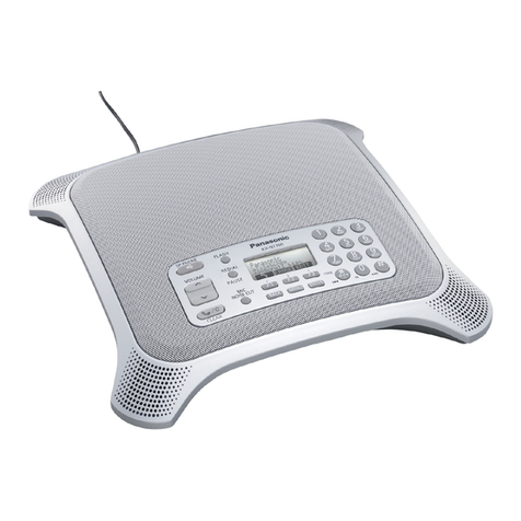
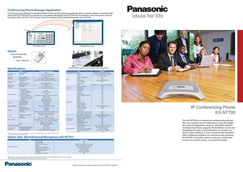
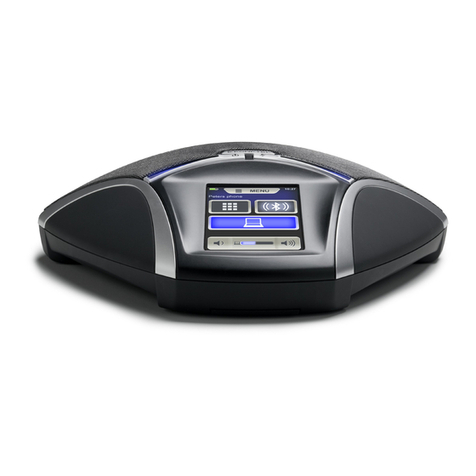
Panasonic VoiceSonic KX-NT700 User manual

Thank you for purchasing this Panasonic product.
This document briefly describes how to connect the unit and introduces commonly used features.
See the Operating Instructions (found on the included CD-ROM) for complete safety information, instructions,
and troubleshooting.
Note: In this manual, the suffix of each model number is omitted unless necessary.
KX-NT700: Version 2.1 or later
Document Version 2010/02
PC Cable (1)
PS Cable (1)
USB Cable (1)
SD Memory Card (1)
KX-NT700NE Only
AC Adaptor (1)
AC Cord
KX-NT700NE/UK/RU/ML: 1 KX-NT700BX: 2
KX-NT700C: PQLV206
KX-NT700AL/NZ: PQLV206AL
(ferrite core added)
KX-NT700NE/UK/RU/BX/ML: PQLV216
KX-NT700NE/RU/BX
KX-NT700UK/BX/ML
Included Accessories
Quick Reference Guide
IP Conferencing Phone
KX-NT700Model No.

For Your Safety
To reduce the risk of injury, loss of life, electric shock,
fire, malfunction, and damage to equipment or property,
always observe the following safety precautions.
WARNING
General Safety
•Do not disassemble this unit. Only qualified
personnel should service this unit. Disassembling
the unit may expose you to dangerous voltages or
other risks. Incorrect reassembly can cause electric
shock.
•Do not insert foreign objects into the unit.
•Do not connect or disconnect the AC plug with wet
hands.
•Disconnect the unit from the AC outlet, disconnect
the LAN cable, and contact the dealer if:
–The AC adaptor cord, AC cord, or AC plug
becomes damaged or frayed.
–The unit is exposed to rain, water, or any other
liquid.
–The unit is dropped or damaged.
–Internal components are exposed due to
damage.
–The unit does not operate properly.
–Performance deteriorates.
•Disconnect the unit from the AC outlet and
disconnect the LAN cable if the unit emits smoke, an
abnormal smell, or makes unusual noise. These
conditions can cause fire or electric shock. Confirm
that smoke has stopped and contact an authorised
service centre.
•Clean the AC plug periodically with a soft, dry cloth
to remove dust and other debris.
Installation
•Do not connect the unit to the AC outlet, AC
extension cords, etc., in a way that exceeds the
power rating of, or does not comply with the
instructions provided with, the AC outlet, AC
extension cords, etc.
•Do not touch the unit, AC adaptor, AC adaptor cord,
AC cord, or telephone cord during a lightning storm.
•Do not install telephone jacks in wet locations unless
the jack is specifically designed for wet locations.
•Do not touch uninsulated telephone wires or
terminals unless the telephone line has been
disconnected at the network interface.
•If using an AC adaptor, use only the included AC
adaptor.
•The AC adaptor should be connected to a vertically
oriented or floor-mounted AC outlet. Do not connect
the AC adaptor to a ceiling-mounted AC outlet, as
the weight of the adaptor may cause it to become
disconnected.
•Only connect the unit to the type of electric power
specified on the label affixed to the unit. Confirm the
type of electric power supplied to the installation site
if necessary.
•Use caution when installing or modifying telephone
lines.
Placement
•Do not expose the unit to contact with liquids (rain,
water, moisture, oil, etc.) or excessive smoke or
dust. Do not subject the unit to excessive shock.
•Do not allow anything to rest on the AC adaptor cord,
AC cord, or LAN cable. Do not locate this unit where
the AC adaptor cord, AC cord, or LAN cable may be
stepped on or tripped on.
•Place this unit on a flat surface. Serious damage
and/or injury may result if the unit falls.
•Allow 10 cm clearance around the unit for proper
ventilation.
CAUTION
•Do not place heavy objects on top of this unit.
•When the unit receives power from the AC adaptor,
the AC adaptor is the main disconnect device.
Ensure that the AC outlet is installed near the unit
and is easily accessible, so that the unit can be
disconnected from the AC outlet if necessary.
•Disconnect the AC adaptor cord and all cables from
the unit before cleaning. Clean the unit with a soft,
dry cloth. Do not use liquid, aerosol cleaners,
abrasive powders, or chemical agents to clean the
unit.
•The SD memory card poses a choking hazard. Keep
the SD memory card out of reach of children.
•When left unused for a long period of time,
disconnect the unit from the AC outlet. When the unit
receives power from a PoE power supply,
disconnect the LAN cable.
For Users in the United Kingdom
For your safety, please read the following text
carefully.
This appliance is supplied with a moulded three-pin
mains plug for your safety and convenience. A 3 amp
fuse is fitted in this plug. Should the fuse need to be
replaced, please ensure that the replacement fuse has
a rating of 3 amps and that it is approved by ASTA or
BSI to BS1362.
2 Quick Reference Guide Document Version 2010/02
Quick Reference Guide

Check for the ASTA mark or the BSI mark on
the body of the fuse. If the plug contains a removable
fuse cover, you must ensure that it is refitted when the
fuse is replaced. If you lose the fuse cover, the plug must
not be used until a replacement cover is obtained. A
replacement fuse cover can be purchased from your
local Panasonic dealer.
IF THE FITTED MOULDED PLUG IS UNSUITABLE
FOR THE AC OUTLET IN YOUR PREMISES, THEN
THE FUSE SHOULD BE REMOVED AND THE PLUG
CUT OFF AND DISPOSED OF SAFELY. THERE IS A
DANGER OF SEVERE ELECTRICAL SHOCK IF THE
CUT-OFF PLUG IS INSERTED INTO ANY 13 AMP
SOCKET.
If a new plug is to be fitted, please observe the wiring
code as shown below. If in any doubt, please consult a
qualified electrician.
IMPORTANT
The wires in the mains lead are coloured as follows:
Blue: Neutral
Brown: Live
As the colours of the wires in the mains lead of this
apparatus may not correspond with the coloured
markings identifying the terminals in your plug, proceed
as follows.
The wire that is coloured BLUE must be connected to
the terminal that is marked with the letter N or coloured
BLACK.
The wire that is coloured BROWN must be connected
to the terminal that is marked with the letter L or coloured
RED.
Under no circumstances should either of these wires be
connected to the earth terminal of the three pin plug,
marked with the letter E or the Earth Symbol .
How to Replace the Fuse
Open the fuse compartment with a screwdriver and
replace the fuse and fuse cover.
or
For Best Performance
•Use the unit in a quiet room. Ambient noise of less
than 50 dBA is recommended.
•Use the unit in a room with minimal echoing. Do not
place the unit near walls, windows, partitions, etc.
•During the first 30 seconds of a TEL call, the unit
adjusts itself for optimal sound quality. Speak in
turns with the other party at the beginning of a
conversation. (The time required varies depending
on the condition of the telephone line and the audio
characteristics of the room.) During this time, sound
may cut out or fade in and out. This is normal.
•Do not obstruct the unit during calls. Keep your
hands, as well as common objects such as folders,
cups, and coffee pots away from the unit during
calls.
Unit Overview
Main View
Unit appearance varies by country or area.
C B
C
G H I J G
B
B
C
E
F
A
B
C
D
Speaker
Indicators (4 locations)
Built-in Microphones (4 locations)
USB Port (USB)
SD Memory Card Slot
AUDIO IN/OUT Jack
External Wired MIC Jacks (EXT MIC1, EXT MIC2)
Telephone Jack (LINE)
LAN Port (LAN)
DC Input (DC IN)
Document Version 2010/02 Quick Reference Guide 3
Quick Reference Guide

Front Panel
KX-NT700C/UK/AL/NZ/BX/ML
A
B
C
DE GF
HIJK L
KX-NT700NE
A
B
C
DE GF
HIJK L
KX-NT700RU
A
B
C
DE GF
HIJK L
Button (Speakerphone Button)
Navigator/Volume Button ([ ] and [ ])
Button (Mute/Clear Button)
FLASH/R Button
REDIAL/PAUSE/ Button
Display
Function Buttons ([F1], [F2], and [F3])
Press a function button to select the function
displayed directly above it. For example, in the
illustration here, press [F3] to select
(phonebook).
MIC NOISE CUT/ Button
BACK Button
MENU Button
ENTER Button
Playback Control Buttons
Basic Connections
E
D
D
A
LINE
LAN DC IN
B
CF
KX-NT700NE
KX-NT700UK
KX-NT700RU
KX-NT700BX
KX-NT700ML
AC Adaptor Cord
LAN Cable
Telephone Cord
To AC Outlet
KX-NT700NE/UK/RU/BX/ML: use the included AC
cord
To Switching Hub
Telephone Jack or PBX
Note
•If "Select Country" is displayed after the unit
turns on, press [] or [ ] repeatedly to select
the country of use, then press
SAVE
.
•If using an AC adaptor, use only the included AC
adaptor.
•To use PoE (Power over Ethernet), connect the
LAN cable to a PoE-compatible (IEEE802.3af)
switching hub. The included AC adaptor does
not need to be connected when using PoE.
Connecting a Portable Station (PS)
A
B
C
AUDIO IN/OUT Jack
PS Cable
Headset jack of PS
Connecting a Computer
Connecting using the USB cable
USB
A
B
4 Quick Reference Guide Document Version 2010/02
Quick Reference Guide
USB Port
USB Cable
Connecting using the PC cable
A
B
C
D
AUDIO IN/OUT Jack
PC Cable
Microphone jack (red) of computer
Headphone jack (green) of computer
Connecting an External Wired MIC
An optional KX-NT701 External Wired MIC can be
connected to the unit using the EXT MIC1 (A) or EXT
MIC2 (B) jacks. 2 mics can be connected.
A
B
Changing the Language
1. Press [MENU].
2. Press [ ] or [ ] repeatedly to select "Basic
Settings".
3. Press [ENTER] two times.
4. Press [ ] or [ ] repeatedly to select the desired
language.
5. Press [ENTER].
6. Press [MENU].
Operation Mode
By selecting an operation mode, the unit operates as a
SIP extension of the PBX, peer to peer IP conferencing
phone or USB audio device of a computer.
1. Press [MENU].
2. Select "Operation Mode", then press
SELECT
.
3. Select the desired setting. (default: "IP-PBX")
•"IP-PBX": The unit can make and receive IP
calls as a SIP extension of the PBX.
•"Peer to Peer": Peer to peer IP calls are
possible. To make a call, the other party’s IP
address is specified.
•"USB Audio": The unit operates as the USB
audio device of a computer.
4. Press
SAVE
.
5. For the new setting to take effect, disconnect the AC
adaptor from the AC outlet, then connect it again to
restart the unit.
•When you are using PoE, disconnect the LAN
cable from the unit, then connect it again.
Line Selection
Whether the TEL line, PS line, or PC line is available is
determined by the "Line Selection" setting.
1. Press [MENU].
2. Press
LINE
.
3. Select the desired setting.
•"IP + TEL": The IP and TEL lines are available.
•"IP + PS": The IP and PS lines are available.
•"IP + PC": The IP and PC lines are available.
4. Press
SAVE
.
5. Press [MENU].
Note
•When the operation mode is set to "USB
Audio", the "Line Selection" cannot be
selected.
•If you select "IP + TEL", change the dial mode
(default: "Tone") if necessary:
[MENU]®select "TEL Settings"®select
"Dial Mode"®select "Pulse" or "Tone"®
SAVE
®[MENU]
IP Network, SIP Settings
To properly connect the unit to an IP network, the
following settings must be set to match the settings of
the IP network.
–IP address mode: Automatic (DHCP) or manual
(static) IP address assignment (default: static)
–IP address (when static connection mode is
selected; default: 192.168.0.2)
–Subnet mask (when static connection mode is
selected; default: 255.255.255.0)
–Default gateway (when static connection mode is
selected; default: 0.0.0.0)
To use the unit as a SIP extension of the PBX, the unit
must be registered as a SIP extension through PBX
programming, the "Operation Mode" setting must be
set to "IP-PBX" (this is the default setting), and the
following settings must be set to match the settings of
the PBX.
Document Version 2010/02 Quick Reference Guide 5
Quick Reference Guide
–SIP Ext. No.
–SIP Password
–SIP User Domain Name
–SIP Proxy Server IP Address
–SIP Proxy Server Port Number
–SIP Registrar IP Address
–SIP Registrar Port Number
Consult your system administrator for the appropriate
settings.
Note
•If these settings are changed, the unit must be
restarted before the new settings become
effective. See the Operating Instructions for
details.
•To confirm the SIP extension number, press
[MENU]®"SIP Ext. No."®
SELECT
.
Making Calls
1. Confirm that the desired line is selected. Change the
selected line by pressing the centre function button
[F2].
A
B
The TEL line is selected (A). The IP line will be
selected when
IP
(B) is pressed.
2. Press [ ].
3. For TEL calls: Enter the phone number.
For IP calls with IP-PBX connection: Enter the
phone number.
For IP calls with peer to peer connection: Enter
the IP address, then press [#] or [ENTER].
•IP addresses can be entered using the keypad.
[0]–[9] are used to enter numbers and [ ] is
used to enter a period.
4. To end the call, press [ ].
Making Calls with a PS or Computer
1. Make or answer a call using the PS or computer, and
confirm that you can talk to and hear the other party.
2. Connect the unit to the PS or computer (see
page 4).
3. Confirm that the desired setting ("PS", "PC" or
"USB-AUDIO") is selected.
•You can change the setting from "Line
Selection" (see page 5) or "Operation
Mode" (see page 5).
A
B
The PS line is selected (A). The IP line will be
selected when
IP
(B) is pressed.
4. Press [ ].
5. End the call with the PS or computer, then press
[ ].
Making Calls from the Phonebook
To add entries to the phonebook, see the Operating
Instructions.
1. Press .
2. Press [ ] or [ ] repeatedly to scroll through the
phonebook entries.
3. When the desired entry is displayed, press [ ] or
.
Note
•The line that was selected when the entry was
stored in the phonebook ("IP" or "TEL") is
shown in the lower-right corner of the display.
This line will be used when the entry is called.
The TEL line will
be used when
you call this
number.
•If the "Line Selection" setting is not set to
"IP + TEL" (see page 5), TEL line numbers
cannot be called.
Making Conference Calls
1. Press
CONF
.
•The current call is put on hold.
2. Confirm that the desired line ("IP" or "TEL") is
selected.
3. Call the party you want to add to the conversation.
4. After the called party answers, press
CONF
to
begin the conference call.
6 Quick Reference Guide Document Version 2010/02
Quick Reference Guide
Note
•When the "Operation Mode" setting is set to
"IP-PBX", only 1 IP call is possible. To have a
conference call, you must use the IP line for 1
party, and the TEL, PS, or PC line for the other
party.
Ending a Conference Call
Press [ ] to disconnect both parties.
or
1. Press
END
.
2. Press [ ] or [ ] to select the party you would like
to remove from the conference, then press
SELECT
.
Answering Calls
1. Press [ ] or
ANSWER
.
2. To end the call, press [ ].
Note
•When "Line Selection" is set to "IP +
PC" or "IP + PS", TEL calls cannot be made or
received.
Receiving a Second Call
While on a call, you can receive a second call, and then
join the 2 calls and establish a conference call.
Confirming the caller then creating a
conference call
1. Press
ANSWER
.
•The first call is put on hold, and you can talk to
the second caller.
•To end the second call, press
END
, then
continue the first call.
2. Press
CONF
to establish a conference call.
Refusing a second call
Press
REJECT
. The second caller is disconnected and
the current call continues.
Note
•When the "Operation Mode" setting is set to
"IP-PBX", only 1 IP call is possible. To have a
conference call, you must use the IP line for 1
party, and the TEL, PS, or PC line for the other
party.
Useful Features
Conferencing Phone Manager (CPM)
CPM is computer software that can be used in
conjunction with the unit. It includes the following useful
features:
•Video conferencing
•Sharing applications
•Making calls using the phonebook or call history
See the Operating Instructions for Conferencing Phone
Manager for more details.
Recording
Conversations and voice memos can be recorded to an
SD memory card (32 MB–2 GB). Insert the SD memory
card with the label side facing up.
To record a conversation, press
REC
during the
conversation.
Speech Speed Conversion
You can adjust the speed of the other party's speech
down during a call by pressing
SPEED
. Press repeatedly
to change the current setting or turn the feature off.
"Slow" is shown on the display while this feature is
active.
Mic Noise Reduction
You can press the [MIC NOISE CUT/ ] button
during a call to reduce the ambient noise that is picked
up by the microphones and sent to the other party. Press
repeatedly to change the current setting or turn the
feature off.
"Noise Cut ON" is shown on the display while this
feature is active.
Document Version 2010/02 Quick Reference Guide 7
Quick Reference Guide

The KX-NT700UK and KX-KT700NE are designed to interwork with the:
•Analogue Public Switched Telephone Network (PSTN) of European countries
Panasonic System Networks Co., Ltd. declares that this equipment is in compliance with the essential requirements
and other relevant provisions of Radio & Telecommunications Terminal Equipment (R&TTE) Directive 1999/5/EC.
Declarations of Conformity for the relevant Panasonic products described in this manual are available for download
by visiting:
http://www.doc.panasonic.de
Contact to Authorised Representative:
Panasonic Testing Centre
Panasonic Marketing Europe GmbH
Winsbergring 15, 22525 Hamburg, Germany
1-62, 4-chome, Minoshima, Hakata-ku, Fukuoka 812-8531, Japan
Copyright:
This material is copyrighted by Panasonic System Networks Co., Ltd., and may be reproduced for internal use only.
All other reproduction, in whole or in part, is prohibited without the written consent of Panasonic System Networks
Co., Ltd.
© Panasonic System Networks Co., Ltd. 2010
PSQX4831WA-UF KK1108HF3020
Other manuals for VoiceSonic KX-NT700
9
Table of contents
Other Panasonic Conference Phone manuals

Panasonic
Panasonic VoiceSonic KX-NT700 User manual

Panasonic
Panasonic KX-TS730AZ User manual

Panasonic
Panasonic KX -T7230 User manual

Panasonic
Panasonic KX-MB2062CXB User manual

Panasonic
Panasonic VoiceSonic KX-NT700 User manual

Panasonic
Panasonic VoiceSonic KX-NT700 User manual

Panasonic
Panasonic KX-FKN510 User manual

Panasonic
Panasonic VoiceSonic KX-NT700 User manual