manuals.online logo
Brands
  1. Home
  2. •
  3. Brands
  4. •
  5. Panasonic
  6. •
  7. DVR
  8. •
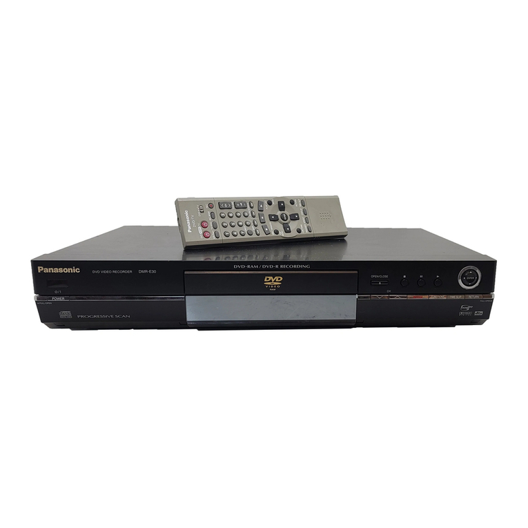
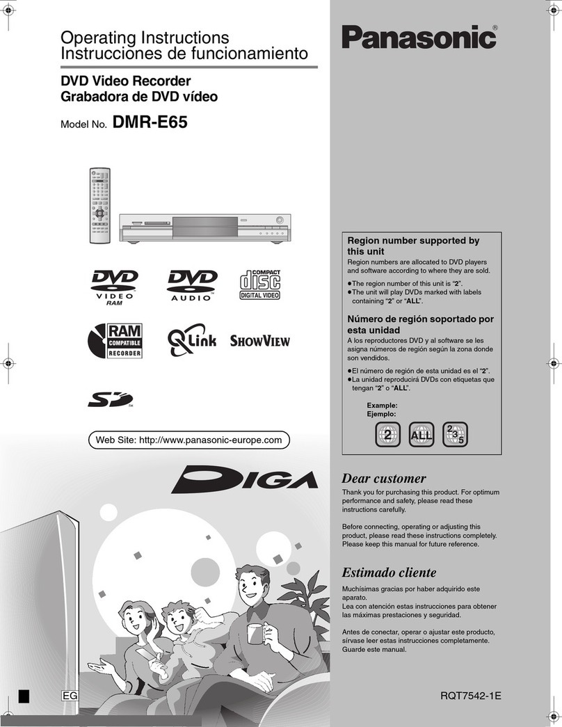
  9. Panasonic DMR-E85HP User manual

Panasonic DMR-E85HP User manual

Other manuals for DMR-E85HP

1

This manual suits for next models

1

Other Panasonic DVR manuals

Panasonic WJ-ND400K Manual

Panasonic

Panasonic WJ-ND400K Manual

Panasonic DMRE80HP Building instructions

Panasonic

Panasonic DMRE80HP Building instructions

Panasonic DMR-E85HEP User manual

Panasonic

Panasonic DMR-E85HEP User manual

Panasonic WJND200 - NETWORK DISK RECORDER Manual

Panasonic

Panasonic WJND200 - NETWORK DISK RECORDER Manual

Panasonic WJ-NT104 User manual

Panasonic

Panasonic WJ-NT104 User manual

Panasonic BB-HNP11CE User manual

Panasonic

Panasonic BB-HNP11CE User manual

Panasonic TU-CTH100 User manual

Panasonic

Panasonic TU-CTH100 User manual

Panasonic DMRHS2 - DVD RECORD.W/HD DRIV User manual

Panasonic

Panasonic DMRHS2 - DVD RECORD.W/HD DRIV User manual

Panasonic WJ-ND300A/10000V User manual

Panasonic

Panasonic WJ-ND300A/10000V User manual

Panasonic LQ-MD800 User manual

Panasonic

Panasonic LQ-MD800 User manual

Panasonic DMRE75VP User manual

Panasonic

Panasonic DMRE75VP User manual

Panasonic WJ-HD616/1000 User manual

Panasonic

Panasonic WJ-HD616/1000 User manual

Panasonic DMR-E85HP User manual

Panasonic

Panasonic DMR-E85HP User manual

Panasonic PocketProDVR MDVR-12 User manual

Panasonic

Panasonic PocketProDVR MDVR-12 User manual

Panasonic DMR-E500HS User manual

Panasonic

Panasonic DMR-E500HS User manual

Panasonic WJ-HDG5 User manual

Panasonic

Panasonic WJ-HDG5 User manual

Panasonic DMRE100HP User manual

Panasonic

Panasonic DMRE100HP User manual

Panasonic WJ-ND200/G User manual

Panasonic

Panasonic WJ-ND200/G User manual

Panasonic DMRE500H - DVD RECORDER DECK User manual

Panasonic

Panasonic DMRE500H - DVD RECORDER DECK User manual

Panasonic AG-CPD20P User manual

Panasonic

Panasonic AG-CPD20P User manual

Panasonic AG6124 User manual

Panasonic

Panasonic AG6124 User manual

Panasonic WJ-NV200K User manual

Panasonic

Panasonic WJ-NV200K User manual

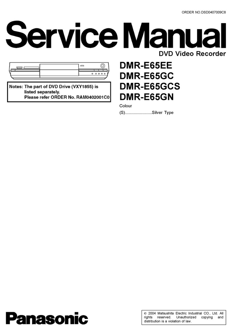
Panasonic DMR-E65EE User manual

Panasonic

Panasonic DMR-E65EE User manual

Panasonic DMR-EH50EB User manual

Panasonic

Panasonic DMR-EH50EB User manual

Popular DVR manuals by other brands

Pace TDC577X manual

Pace

Pace TDC577X manual

Zavio NQ2040 user manual

Zavio

Zavio NQ2040 user manual

KGuard Security KG-SHA104 user manual

KGuard Security

KGuard Security KG-SHA104 user manual

SanDisk V-Mate Quick manual

SanDisk

SanDisk V-Mate Quick manual

Hunt Electronic HVRM-T1600Q Install & user's guide

Hunt Electronic

Hunt Electronic HVRM-T1600Q Install & user's guide

Portwell PIVS-6104 user manual

Portwell

Portwell PIVS-6104 user manual

AVer EXR6004 Mini Quick user guide

AVer

AVer EXR6004 Mini Quick user guide

Security Labs SLD261 owner's manual

Security Labs

Security Labs SLD261 owner's manual

Swann DIGITAL VIDEO RECORDER instruction manual

Swann

Swann DIGITAL VIDEO RECORDER instruction manual

EverFocus ECOR 4 instruction manual

EverFocus

EverFocus ECOR 4 instruction manual

Xoro HRK 7550 user manual

Xoro

Xoro HRK 7550 user manual

FLIR M3100E Series instruction manual

FLIR

FLIR M3100E Series instruction manual

VTRACKPRO FPRO300 user manual

VTRACKPRO

VTRACKPRO FPRO300 user manual

Swann NVR-7085 models instruction manual

Swann

Swann NVR-7085 models instruction manual

RMRC FPV1000 manual

RMRC

RMRC FPV1000 manual

urmet domus 1093/004AHD instructions

urmet domus

urmet domus 1093/004AHD instructions

Toshiba D-VR3SU Service manual

Toshiba

Toshiba D-VR3SU Service manual

CMOS DOTCOM ANX-1670 manual

CMOS DOTCOM

CMOS DOTCOM ANX-1670 manual

manuals.online logo
manuals.online logoBrands
  • About & Mission
  • Contact us
  • Privacy Policy
  • Terms and Conditions

Copyright 2025 Manuals.Online. All Rights Reserved.

ORDERNO.DSD0403003C1
B24
DVDVideoRecorder
DMR-E85HP/ DMR-E85HPC
Colour
(S).......................SilverType
SPECIFICATIONS
1
1. Safetyprecautions
1.1. General guidelines
1. Whenservicing, observetheoriginal leaddress. Ifashortcircuit
isfound, replace all parts whichhavebeenoverheatedor
damagedbytheshortcircuit.
2. Afterservicing, see toitthat all theprotectivedevices suchas
insulation barriers, insulation papersshieldsareproperlyinstalled.
2
3. Afterservicing, make thefollowing leakagecurrentchecks to
preventthecustomerfrombeing exposedtoshock hazards.
1.1.1. Leakagecurrentcoldcheck
1. Unplug theACcordand connect ajumperbetweenthetwoprongs
on theplug.
2. Measuretheresistance value, withanohmmeter, betweenthe
jumperedACplug and eachexposedmetalliccabinet parton the
equipmentsuchas screwheads, connectors, control shafts, etc.
Whentheexposedmetallicparthas areturnpathtothechassis,
thereading shouldbebetween1M and 5.2M . / Whenthe
exposedmetal does nothaveareturnpathtothechassis, the
reading must be . Figure1
1.1.2. Leakagecurrenthotcheck / (See Figure 1 .)
1. Plug theACcorddirectlyintotheACoutlet. Donotuse an
isolation transformerforthischeck.
2. Connect a1.5k , 10 watts resistor, inparallel witha0.15 F
capacitors, betweeneachexposedmetallicparton theset and a
good earthground suchas awaterpipe, as shownin Figure1.
3. Use anACvoltmeter, with1000 ohms/voltormoresensitivity, to
measurethepotential across theresistor.
4. Check eachexposedmetallicpart, and measurethevoltageat
eachpoint.
5. Reverse theACplug intheACoutlet and repeat eachoftheabove
measurements.
6. Thepotential at anypointshouldnotexceed0.75 volts RMS. A
leakagecurrenttester(Simpson Model 229 orequivalent) maybe
usedtomake thehotchecks, leakagecurrentmust notexceed1/2
3
milliampere. Incase ameasurementisoutsideofthelimits
specified, thereisapossibilityofashock hazard, and the
equipmentshouldberepairedand recheckedbeforeitisreturned
tothecustomer.
1.2. Caution forfuse replacement
2. Prevention of ElectrostaticDischarge (ESD) to
ElectrostaticSensitive(ES) Devices
Somesemiconductor (solidstate)devices canbedamagedeasilybystaticelectricity. Such
componentscommonlyarecalledElectrostaticSensitive (ES)Devices. Examples oftypical ES
devices areintegratedcircuitsand somefield-effecttransistor-sandsemiconductor "chip"
components. Thefollowing techniques shouldbeusedtohelpreduce theincidence of
componentdamagecausedbyelectrostaticdischarge(ESD).
1. Immediatelybeforehandling anysemiconductorcomponentor
semiconductor-equippedassembly, drainoff anyESDon your
bodybytouching aknownearthground. Alternatively, obtainand
wearacommerciallyavailabledischarging ESDwrist strap,
whichshouldberemovedforpotential shock reasonspriorto
applying powertotheunitundertest.
2. Afterremoving anelectrical assemblyequippedwithES devices,
place theassemblyon aconductivesurface suchas aluminum
foil, topreventelectrostaticchargebuildup orexposureofthe
assembly.
3. Use onlyagrounded-tipsoldering iron tosolderorunsolderES
devices.
4. Use onlyananti-staticsolderremoval device. Somesolder
removal devices notclassifiedas "anti-static(ESDprotected)"can
generate electrical chargesufficienttodamageES devices.
5. Donotuse freon-propelledchemicals. These cangenerate
electrical charges sufficienttodamageES devices.
6. DonotremoveareplacementES device fromits protective
4
packageuntil immediatelybeforeyou arereadytoinstall it. (Most
replacementES devices arepackagedwithleadselectrically
shortedtogetherbyconductivefoam, aluminumfoil or
comparableconductivematerial).
7. Immediatelybeforeremoving theprotectivematerial fromthe
leadsofareplacementES device, touchtheprotectivematerial to
thechassisorcircuitassemblyintowhichthedevice will be
installed.
Caution
Besureno powerisappliedtothechassisorcircuit, and observe
all othersafetyprecautions.
8. Minimizebodilymotionswhenhandling unpackagedreplacement
ES devices. (Otherwise hamless motion suchas thebrushing
togetherofyourclothes fabricorthelifting ofyourfootfroma
carpetedfloorcangenerate staticelectricitysufficienttodamage
anES device).
3. Precaution of LaserDiode
5
4. Howtoreplace the LithiumBattery
REPLACEMENTPROCEDURE
1. RemovetheTop case and DVD-RAMdriveunitwithMainP.C.B. by
referring theDisassembling Procedure.
2. UnsoldertheLithiumBatteries:B7501 and thenreplace itintonew
one.
(Asshownin20.2.1. TheMainP.C.B. )
NOTE:
Thelithium batteryisacritical component. (TypeNo.:CR2354-1GUFManufacturedby
Panasonic. )
Itmustneverbesubjectedtoexcessive heator discharge.
Itmustthereforeonlybefittedinequipmentdesignedspecificallyfor itsuse.
Replacementbatteries mustbeofthesametypeand manufacture.
They mustbefittedinthesamemannerand location as theoriginal battery, withthecorrect
polaritycontactsobserved.
Donotattempttore-chargetheoldbatteryor re-use itfor anyotherpurpose.
Itshouldbedisposedofinwasteproductsdestinedfor burial ratherthanincineration.
6
5. Handling the Lead-free Solder
5.1. Aboutleadfree solder(PbF)
Distinction ofPbF P.C.B.:
P.C.B.s(manufactured)using leadfree solderwill have aPbF stampon theP.C.B.
Caution:
-Pbfree solderhas ahighermelting pointthanstandardsolder;
Typicallythemelting pointis50 -70°F(30 -40°C)higher. Please
use ahigh temperaturesoldering iron. Incase ofthesoldering iron
withtemperaturecontrol,please set itto700 ±20°F(370 ±10°C).
-Pbfree solderwill tend tosplashwhenheatedtoo high (about
1100°F/600°C).
-Whensoldering orunsoldering, please completelyremoveall ofthe
solderon thepinsorsolderarea, and besuretoheat thesoldering
points withthePbfree solderuntil itmelts enough.
6. Each Buttons
7. NewFeatures
7.1. Function ofPowerCircuit(IC1150)
1. General
WeadoptedICmoduleas theSwitching PowerCircuitfor lowerpowerconsumption.
IC1150 isconstructedwithSwitching materialsand Control IC, and ispartial resonance module.
WerealizedSwitching Powerwithhigh efficiency, lownoise and lowpowerconsumption.
2. Equivalence CircuittoIC1150
7
Pin
No. Symbol Description
1 Z/C Triggerinputterminal.
Zero detection voltage:0.25V
Itbecomes less than3V, themode
turnstostandby.
2F/B Bias currentfeedback inputterminal.
Switching ONtime(min.)~(max.)
1.5V ~4.5V / 0 sec. ~25 sec.
Instandbymode
Oscillation stops:less than0.8V
Oscillation starts:over1.8V
3GND GND terminal
4Vcc Powerterminal ofIC.
Oscillation starting voltage:Vcc =
and over14.5V
Oscillation stop voltage:Vcc =and
less than9.6V
Overvoltagelatching voltage:Vcc =
20V
5Drain Drainterminal for Mainswitching
material.
3. Startup Circuit
Whenpoweristurnedon, inputvoltageoftheSwitching TransformerissuppliedtoIC1150 as the
startup power.
8
AfterIC1150 has started, thestartup currentiscutoff.
ThecurrentofStartup Circuitissuppliedas constantcurrentsource inIC1150 and as charge
currentfor thecapacitor connectedbetweenVcc terminal and GND outsideofIC1150 until Vcc
reaches 14.4V.
WhenVcc reaches 14.4V, theStartup Circuitiscutoff, thenoscillation starts.
Afterthen, powerofIC1150 issuppliedfrom control coil.
Incase, thepowerfailureor shortoutoftheload, whenVcc becomes 9.0V;theoscillation stops,
furthermoreVcc becomes 7.1V theStartup Circuitstartsup and Vcc startstorise.
Startup CircuitTiming Chart
Function ofZ/CTerminal
WhenvoltageofZ/Creaches 0.25V, Gatesignal isoutputand Draincurrentstartstoflow.
Function ofF/Bterminal
F/Bsignal decides Switching ONwidthinlowvoltagecontrolling.
9
TheSwitching ONwidthrespondstochangeofF/BVoltage.
StandbyFunction
WhenZ/CVoltagebecomes less than3V, theunitchanges toStandbymode.
IC1150 Block Diagram
Signal name
PinNo. Name Symbol
1 Zero CurrentDet. Z/C
2Feedback F/B
3GND GND
4Vcc Vcc
5Drain Drain
8. Taking out the Disc fromRAM-DriveUnit when the
10