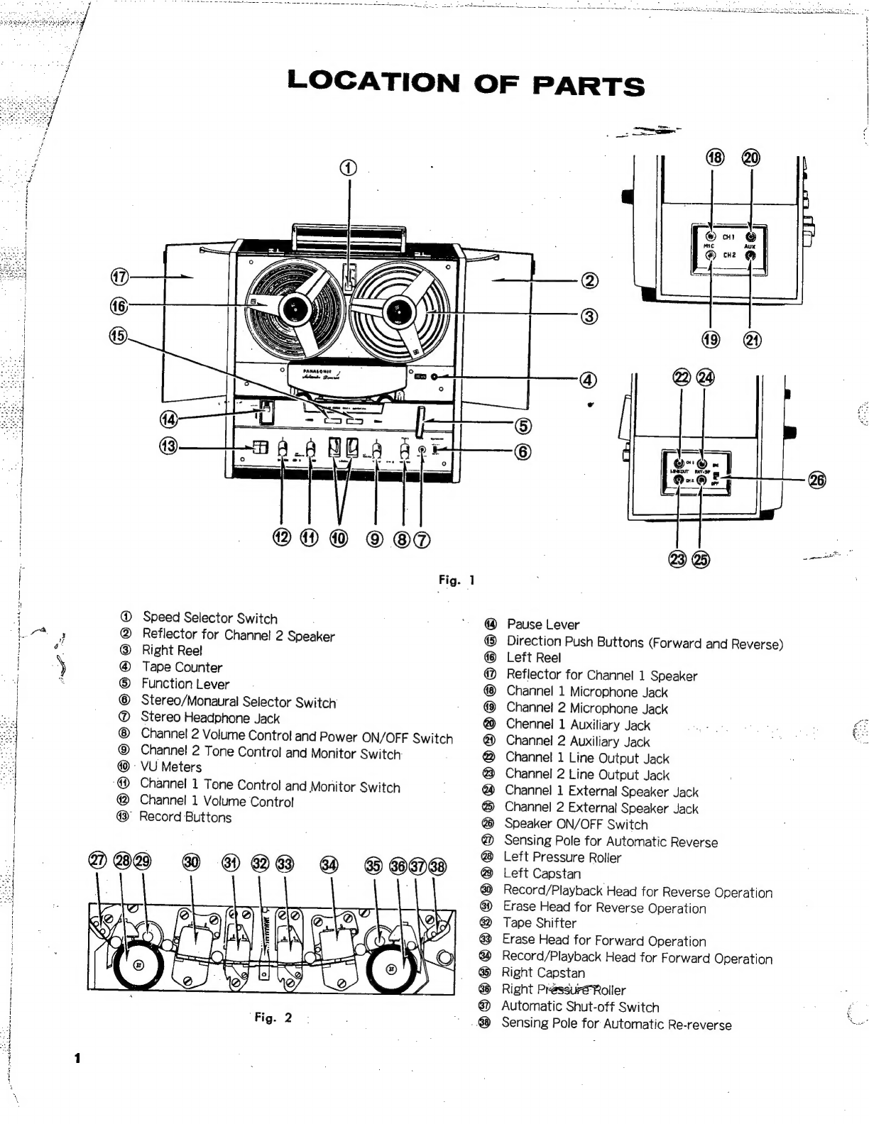
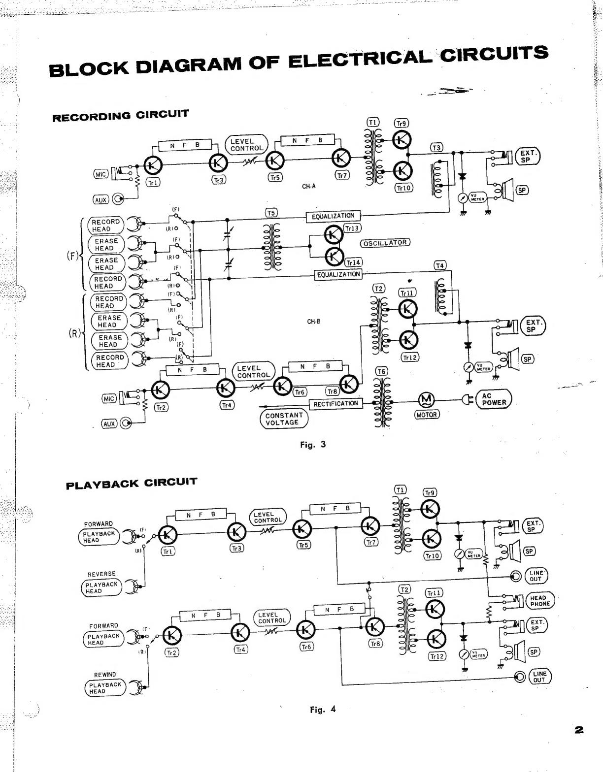
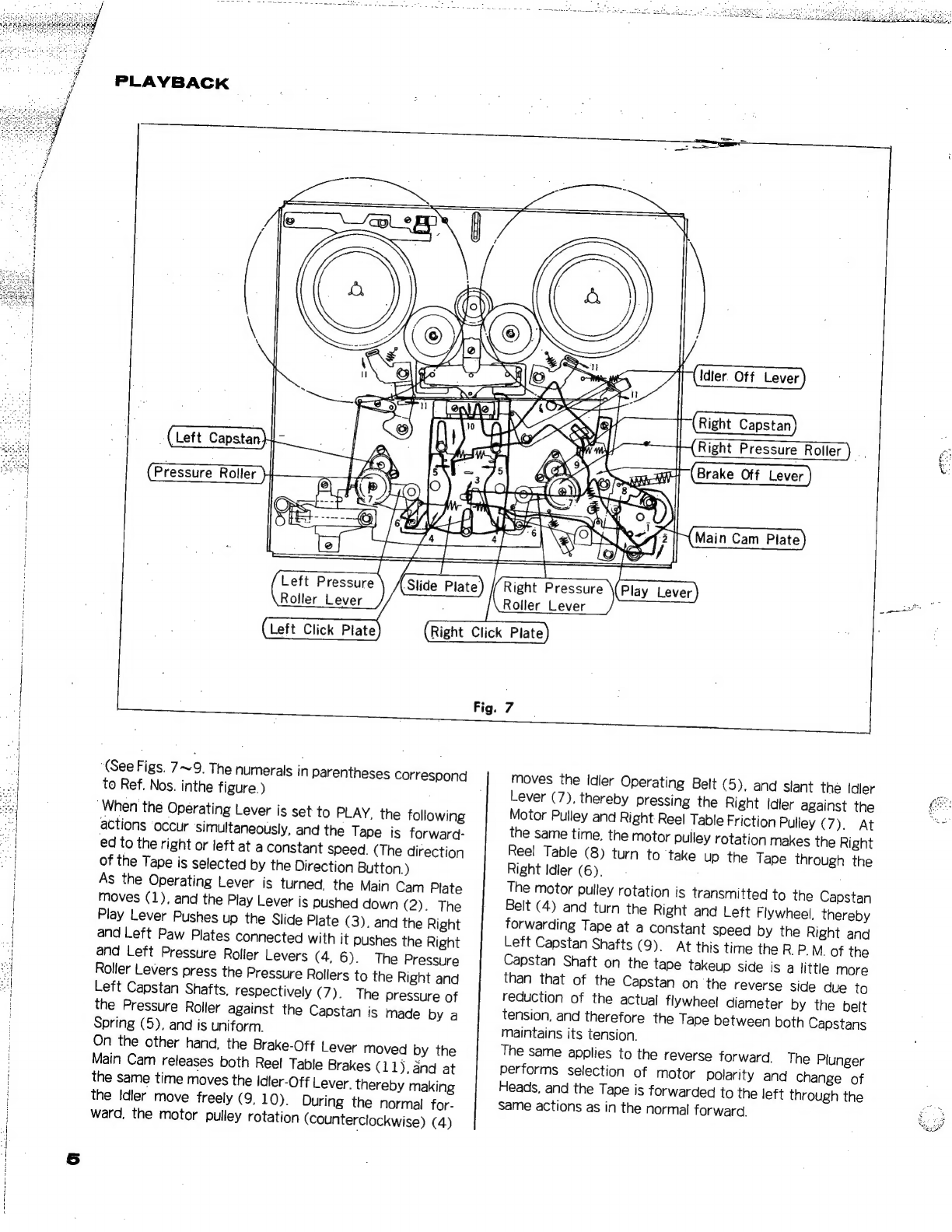
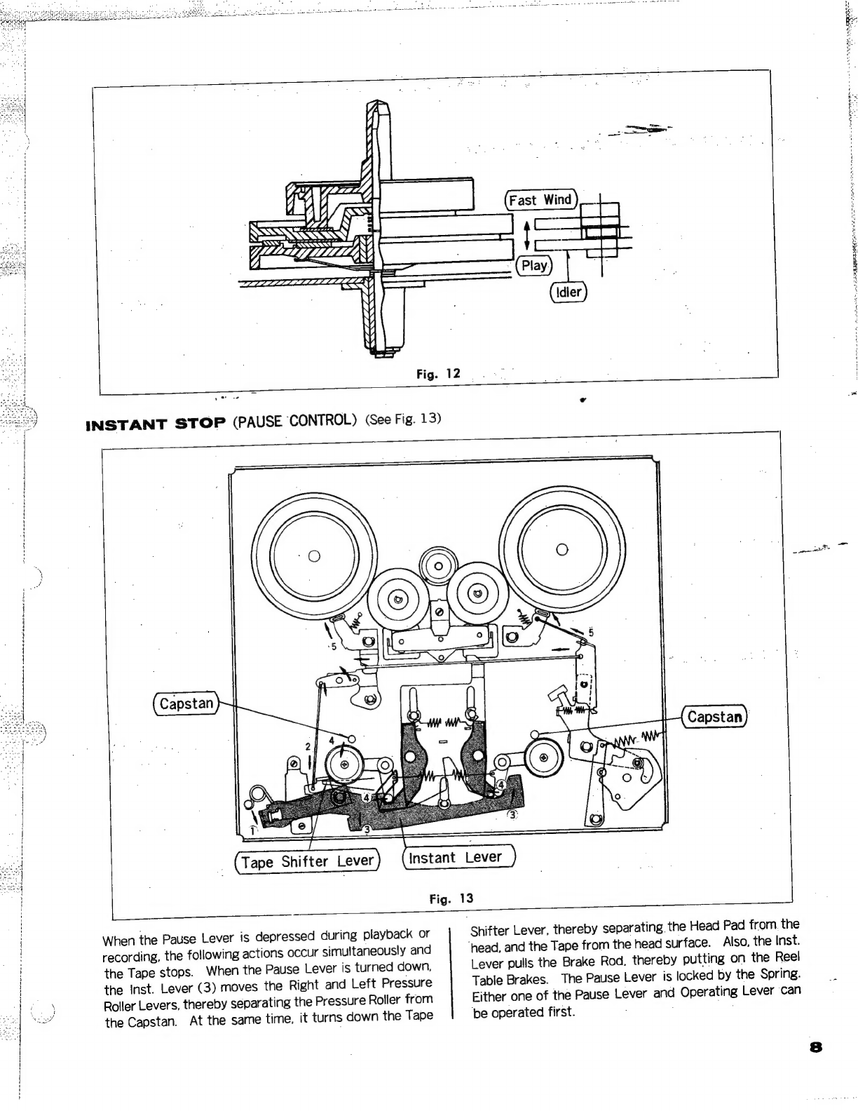
Panasonic RS-790S User manual
Other Panasonic Measuring Instrument manuals

Panasonic
Panasonic EYFR02 User manual

Panasonic
Panasonic KW1M-H User manual

Panasonic
Panasonic AG6124 User manual

Panasonic
Panasonic KW9M Eco-Power Meter User manual

Panasonic
Panasonic KW9M Eco-Power Meter User manual

Panasonic
Panasonic PV-V4524S User manual

Panasonic
Panasonic WJ-NV300K/GJ User manual

Panasonic
Panasonic AJ-PG50EJ User manual

Panasonic
Panasonic RRQR100 - IC RECORDER User manual

Panasonic
Panasonic FZ-VNP001U User manual

Panasonic
Panasonic KW9M Eco-Power Meter User manual

Panasonic
Panasonic ShowStopper PV-SS2710 User manual

Panasonic
Panasonic DMR-HW220 User manual

Panasonic
Panasonic LP-GS Series User manual

Panasonic
Panasonic Omnivision PV-V4600 User manual

Panasonic
Panasonic MKG1500-DE User manual

Panasonic
Panasonic AG-RT850P User manual

Panasonic
Panasonic KW4S User manual

Panasonic
Panasonic WJHD500 - DIGITAL DISC RECORDE User manual

Panasonic
Panasonic LP-400 Series Use and maintenance manual