7 Precautions When
Executing The Main PCB
Replacement Service
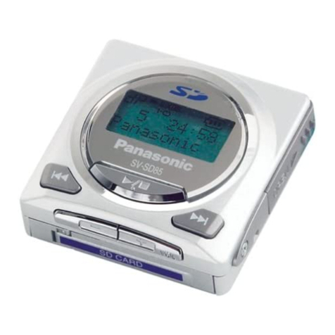
This mode is used to check unit operation and the condition of
the PCB, and to verify that record/playback operations are
occurring normally.
Always set the audio player to the service mode when replacing
the PCB or IC. The service mode is also used for initializing and
writing setting data.
8.1. Before Entering The Service
Mode
Preparations
The following items are required in order to perform an
operation check
·Rechargeable battery (accessory item) (must be fully
charged)
·One SD card (service mode card)
·One SD card with 8MB space available (for recording
check)
·Accessory USB cable
·Personal computer with accessory SD-Jukebox Ver.5.0
installed
8.1.1. Preparing The Service Mode SD-
Card
Preparation procedure for SD card
1. Connect the audio player to the personal computer
where the accessory SD-Jukebox Ver.5.0 software is
installed.
2. Insert the SD-card.
3. Use SD-Jukebox Ver.5.0 to write a music file to the SD-
card.
4. End SD-Jukebox Ver.5.0 operation.
5. Download the necessary files (SD100TST.SDA and
FLASH_WR.BIN) from TSN-WEB (Support Information
From NWBG-PAVC).
6. Copy the files (SD100TST.SDA and FLASH_WR.BIN)
into the SD-card´s root directory.(The personal
computer recognizes the audio player as a removable
disk.)
7. Disconnect the audio player from the personal
computer.
8. Perform a voice recording to the SD-card at the audio
player.
Note:
If you may not be able to complete a downloding from
the TSN-WEB page, Please order a jig SD card
(RFKZ0294) or obtain the files (SD100TST.SDA and
FLASH_WR.BIN) through your local Panasonic Service
Organization.
The supplied device key loaded PCB (REP3902A-M) does not
contain the regional default settings file.
That file must be written to the audio player by the procedure
shown below.
1. Execute the "8.9. SERVICE 7: Default Settings Writing"
procedure".
Preparation procedure for jig SD card
1. Connect the audio player to the personal computer
where the accessory SD-Jukebox Ver.5.0 software is
installed.
2. Insert the jig SD-card (RFKZ0294).
3. Open the jig SD-card from the personal computer. (The
personal computer recognizes the audio player as a
removable disk.)
·The SD-card´s root directory contains the
SD100TST.SDA service mode file, and
FLASH_WR_XXXXXXXX.BIN*regional default
settings file.
* "XXXXXXXX" denotes the region and model
names.
4. Change the file name of the desired region´s
FLASH_WR_XXXXXXXX.BIN to "FLASH_WR.BIN".
5. Use SD-Jukebox Ver.5.0 to write a music file to the SD-
card.
6. End SD-Jukebox Ver.5.0 operation.
7. Disconnect the audio player from the personal
computer.
8. Perform a voice recording to the SD-card at the audio
player.
* Use the service mode´s "audio playback check" and
"voice playback check" functions for audio files and voice
files.
Because the time required for this operation is determined
by the length of the file, the file should be as short as
possible.
8.1.2. Preparing The Recording Check
SD-Card
1. Connect the audio player to the personal computer where
the accessory SD-Jukebox Ver.5.0 software is installed.
2. Format an 8MB SD-card at SD-Jukebox Ver.5.0.
3. Disconnect the audio player from the personal computer.
* This card will be used for the "voice recording check"
and "FM recording check" functions. The time required for
this operation depends on the SD-card capacity.
When using an 8MB SD-card, one "SD-card formatting, full
recording and playback" cycle takes approximately 1 hour.
8 Service Mode
9
SV-SD100VEB / SV-SD100VEG / SV-SD100VGC / SV-SD100VGK / SV-SD100VGN / SV-SD100VPP

