manuals.online logo
Brands
  1. Home
  2. •
  3. Brands
  4. •
  5. Panasonic
  6. •
  7. Speakers System
  8. •
  9. Panasonic SA-HT535EE User manual

Panasonic SA-HT535EE User manual

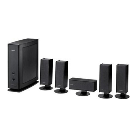
ORDERNO. MD0508309C3
DVDHome Theater Sound System
SA-HT535EE
Colour
(S)...Silver Type
SPECIFICATIONS
Specification
1
PDFcreated withpdfFactoryProtrialversion www.pdffactory.com
Amplifier Section
RMS Output Power: DolbyDigital Mode
Front Ch
55 Wper channel (6), 1kHz, 10%THD
Surround Ch
55 Wper channel (6), 1kHz, 10%THD
Center Ch
160 Wper channel (6), 1kHz, 10%THD
Subwoofer Ch
220 Wper channel (4), 100 Hz, 10%THD
Total RMS DolbyDigital Mode
Power
600 W
DIN Output Power: DolbyDigital Mode
Front Ch
40 Wper channel (6), 1kHz, 1%THD
Surround Ch
40 Wper channel (6), 1kHz, 1%THD
Center Ch
120 Wper channel (6), 1kHz, 1%THD
Subwoofer Ch
150 Wper channel (4), 100 Hz, 1%THD
Total DIN DolbyDigital Mode
Power
430 W
FM/AM Tuner, Terminals
Section
Preset station FM 15 stations
AM/MW15 stations
FrequencyModulation (FM)
FrequencyRange
87.50-108.00 MHz (50-kHz step)
Sensitivity 1.5V (IHF)
S/N 26 dB 1.2V
Antennaterminals 75 (unbalanced)
AmplitudeModulation (AM/MW)
FrequencyRange 522-1629 kHz (9-kHz step)
AM SensitivityS/N 20 dB at 999
kHz
560 V/m
PhoneJack
Terminal Stereo, 3.5mm jack
MicJack
Sensitivity 0.7mV, 1.2k
Terminal Mono, 6.3mm jack (2
systems)
Disc Section
Disc played[8cm or12 cm]
1. DVD (DVD-Video, DVD-Audio, DivX*1, 2)
2. DVD-RAM (DVD-VR, JPEG*2, 3, MPEG4*2, 4, DivX*1, 2)
3. DVD-R (DVD-Video, DivX*1, 2)
4. DVD-RW(DVD-Video, DVD-VR, DivX*1, 2)
5. +R/+RW(Video)
2
PDFcreated withpdfFactoryProtrialversion www.pdffactory.com
6. CD, CD-R/RW[CD-DA, Video-CD, SVCD*5, MP3*2, 6, WMA*2, 7,
JPEG*2, 3, MPEG*2, 4, DivX*1, 2, HIGHMATLevel 2(Audioand
Image)]
*1 DivX 3.11, 4.x, 5.x
GMC (Global Motion Compensation) isnot supported.
*2 Thetotal combinedmaximumnumber of recognizableaudio,
picture and videocontentsand groups: 4000 audio, picture and
videocontentsand 400 groups.
*3 Exif Ver 2.1JPEG Baselinefiles
Picture resolution: between160 X 120 and 6144 X 4096 pixels
(Sub sampling is4:2:2or4:2:0)
*4 MPEG4datarecordedwithPanasonicSD multi-cameras or
DVD videorecorders
Conforming toSD VIDEO specifications(ASFstandard)/MPEG4
(SimpleProfile) videosystem/G.726 audiosystem
*5 Conforming toIEC62107.
*6 MPEG-1Layer 3, MPEG-2Layer 3.
*7 WindowsMediaAudioVer.9.0L3.
Not compatiblewithMultipleBit Rate(MBR)
Pick up
Wavelength CD 785 nm
DVD 662 nm
Laser power CLASS 2/CLASS 3A
Audiooutput (Disc)
Number of channels 5.1ch(FL, FR, C, SL, SR, SW)
VideoSection
VideoSystem
Signal system PAL625/50, PAL525/60, NTSC
Compositevideooutput
Output level 1 Vp-p(75 )
Terminal Pinjack (1system)
Scart jack (1system)
S-videooutput
Y output level 1 Vp-p(75 )
C output level PAL; 0.3Vp-p(75 )
NTSC; 0.286 Vp-p(75 )
Terminal S terminal (1system)
Scart jack (1system)
Component VideoOutput
[NTSC: 525 (480) p/525 (480) i, PAL: 625 (576) p/625 (576)i]
Y output level 1 Vp-p(75 )
PBoutput level 0.7Vp-p(75 )
PRoutput level 0.7Vp-p(75 )
Terminal
Pinjack (Y: green, PB: blue, PR: red) (1system)
RGB videooutput
R output level 0.7Vp-p(75 )
G output level 0.7Vp-p(75 )
B output level 0.7Vp-p(75 )
Terminal Scart jack (1system)
General
3
PDFcreated withpdfFactoryProtrialversion www.pdffactory.com
Power Supply AC 230 V, 50 Hz
Power consumption 25 W(SA-HT535), / 250 W(SB
-WA535)
Dimensions(WxH xD) 430 x60 x348.3mm
Mass 2.7kg(SA-HT535)
Operating temperature range +5°C to+35 °C
Operating humidityrange
5%to90 %RH (no condensation)
Power consumption instandbymode: approx. 0.7W
*8Rating withlowcut filter equippedamplifier
System
System: SC-HT535 (EE)
Mainunit: SA-HT535 (EE-S)
Satellitespeaker: SB-HT535 (EG-S)
Activesubwoofer: SB-WA535 (EE-S)
Speakers: SB-HT535 (EG)
Front speakers: SB-FS535 (EG-S)
Surround speakers: SB-FS536 (EG-S)
Center speaker: SB-PC535 (EG-S)
Note:
1. Specificationsaresubject to changewithoutnotice. Mass and
dimensionsareapproximate.
2. Total harmonicdistortion ismeasured bythedigital spectrum analyzer.
2005 Matsushita ElectricIndustrial Co. Ltd.. All rights reserved.
Unauthorized copying and distribution isaviolation of law.
1. Use of Active Subwoofer
1.1. Checking MainUnitwhen Active Subwoofer isUsed
4
PDFcreated withpdfFactoryProtrialversion www.pdffactory.com
1.2. Checking MainUnitUsing Power Jig
If the active subwooferis not available during time of repairtothe unit, the following equipment
couldbe used.
Jigproduct number
RFKZ0182 (110V , 127V, 220V, 230V - 240V forwithvoltage selectoroverseas domestic use).
2. Before Repair and Adjustment (Using Active
5
PDFcreated withpdfFactoryProtrialversion www.pdffactory.com
Subwoofer Unit)
Disconnect AC power, discharge PowerSupplyCapacitors C2080 through a 10 , 10 W resistor
toground.
DO NOTSHORT-CIRCUITDIRECTLY (witha screwdriverblade, forinstance), as this may
destroysolidstate devices.
Afterrepairs are completed, restore powergraduallyusing a variac, toavoidovercurrent.
Current consumption at AC 230V, 50Hz inNO SIGNALmode shouldbe ~850 mA (Active
Subwoofer).
3. SAFETY PRECAUTIONS
3.1. GENERALGUIDELINES
1. When servicing, observe the original lead dress. Ifashort circuit
isfound, replace all parts which have been overheated or
damaged bythe short circuit.
2. After servicing, ensure that all the protective devices such as
insulation barriers, insulation papers shields are properly
installed.
3. After servicing, make the following leakage current checks to
prevent the customer from being exposed to shock hazards.
3.1.1. LEAKAGE CURRENTCOLD CHECK (FOR ACTIVE SUBWOOFER)
1. Unplug the AC cord and connect ajumper between the two
prongs on the plug.
2. Measure the resistance value, with an ohmmeter, between the
jumpered AC plug and each exposed metalliccabinet part on the
equipment such as screwheads, connectors, control shafts, etc.
When the exposed metallicpart has areturn path to the chassis,
the reading shouldbe between 1M and 5.2 . / When the
exposed metal does not have areturn path to the chassis, the
reading must be .
Fig. 1
3.1.2. LEAKAGE CURRENTHOTCHECK (See Figure1.)
6
PDFcreated withpdfFactoryProtrialversion www.pdffactory.com
1. Plug the AC cord directlyinto the AC outlet. Donot use an
isolation transformer for thischeck.
2. Connect a1.5k , 10 watts resistor, inparallel with a0.15 F
capacitor, between each exposed metallicpart on the set and a
good earth ground such as awater pipe, as showninFigure 1.
3. Use an AC voltmeter, with 1000 ohms/voltor more sensitivity, to
measure the potential across the resistor.
4. Check each exposed metallicpart, and measure the voltage at
each point.
5. Reverse the AC plug inthe AC outlet and repeat each of the above
measurements.
6. The potential at anypoint shouldnot exceed 0.75 volts RMS. A
leakage current tester (Simpson Model 229 or equivalent) maybe
used to make the hot checks, leakage current must not exceed 1/2
milliamp. Incase ameasurement isoutside of the limits specified,
there isapossibilityof ashock hazard, and the equipment should
be repaired and rechecked before itisreturned to the customer.
4. Handling the Lead Solder
4.1. About lead free solder (PbF)
Distinction of PbF P.C.B. :
P.C.B.s (manufactured) using leadfree solderwill have a PbF stampon the P.C.B.
Caution:
-Pb free solder has ahigher melting point that standard solder;
Typicallythe melting point is50 -70°F (30 -40°C)higher. / Please
use ahigh temperature soldering iron. Incase of the soldering
iron with temperature control, please set itto 700 ± 20°F (370 ±
10°C).
-Pb free solder will tend to splash when heated too high (about
1100°F/600°C).
-When soldering or unsoldering, please completelyremove all of
the solder on the pins or solder area, and be sure to heat the
soldering points with the Pb free solder until itmelts enough.
5. Protection Circuitry
The protection circuitrymayhave operatedif eitherof the following conditions are noticed:
7
PDFcreated withpdfFactoryProtrialversion www.pdffactory.com
-Nosound isheard when the power isturned on.
-Sound stops during aperformance.
The function of this circuitryis toprevent circuitrydamage if, forexample, the positive and
negative speakerconnection wires are
“shorted”, orif speakersystems withanimpedance less thanthe indicatedratedimpedance of
the amplifierare used.
If this occurs, followthe procedure outlines below:
1. Turn off the power.
2. Determine the cause of the problem and correct it.
3. Turn on the power once againafter one minute.
Note :
Whenthe protection circuitryfunctions, the unit will not operate unless the poweris first turned
off and thenon again.
6. Prevention of Electro Static Discharge (ESD) to
Electrostatically Sensitive (ES) Devices
Some semiconductor(solidstate) devices canbe damagedeasilybyelectricity. Such
components commonlyare calledElectrostaticallySensitive (ES) Devices. Examples of typical
ES devices are integratedcircuits and some field-effect transistors and semiconductor“chip”
components. The following techniques shouldbe usedtohelpreduce the incidence of
component damage causedbyelectrostatic discharge (ESD).
1. Immediatelybefore handling anysemiconductor component or
semiconductor-equiped assembly, drainoff anyESDon your
bodybytouching aknownearth ground. Alternatively, obtainand
wear acommerciallyavailabledischarging ESDwrist strap, which
shouldbe removed for potential shock reasons prior to applying
power to the unitunder test.
2. After removing an electrical assemblyequiped with ES devices,
place the assemblyon aconductive surface such as aluminium
foil, to prevent electrostaticcharge buildup or exposure of the
assembly.
3. Use onlyagrounded-tipsoldering iron to solder or unsolder ES
devices.
4. Use onlyan anti-staticsolder remover device. Some solder
removal devices not classified as “anti-static(ESDprotected)”
can generate electrical charge to damage ES devices.
5. Donot use freon-propelled chemicals. These can generate
electrical charges sufficient to damage ES devices.
8
PDFcreated withpdfFactoryProtrialversion www.pdffactory.com
6. Donot remove areplacement ES device from its protective
package until immediatelybefore you are readyto install it. (Most
replacement ES devices are packaged with leads electrically
shorted together byconductive foam, aluminium foil or
comparableconductive material).
7. Immediatelybefore removing the protective material from the
leads of areplacement ES device, touch the protective material to
the chassisor circuitassemblyinto which the device will be
installed.
Caution
Besure no power isapplied to the chassisor circuit, and observe
all other safetyprecautions.
8. Minimize bodilymotions when handling unpackaged replacement
ES devices. (Otherwise harmless motion such as the brushing
together of your clothes fabricor the lifting of your foot from a
carpeted floor can generate staticelectricity(ESD)sufficient to
damage an ES device).
7. Cautions to Be Taken When Handling Optical
Pickup
-The laser diode used inside the optical pickup couldbe destroyed
due to staticelectricity(potential difference iscaused by
electrostaticload discharged from clothes and human body).
Handlethe parts carefullyto avoidelectrostaticdestruction during
repair&during replacement.
7.1. Handling Optical Pickup
1. Donot cause anystrong impact on optical pickup as the unit
structurallyuses an extremelyprecise technology.
2. Short-circuitthe flexiblecableof optical pickup removed from the
circuitboard using ashort-circuitpinor clipinorder to prevent
laser diode from electrostaticdestruction. (Refer to Fig. 7-1 and
9
PDFcreated withpdfFactoryProtrialversion www.pdffactory.com
Fig. 7-2.)
3. Donot handleflexiblecables forciblyas thismaycause snapping.
Handlethe parts carefully. (Refer to Fig. 7-1)
4. Anew optical pickup isequipped with an anti-staticflexiblecable.
After replacing and connecting to the flexibleboard, cut the anti-
staticflexiblecable. (Refer to Fig. 7-1)
Fig. 7-1
Fig. 7-2
7.2. Cautions to BeTaken During Replacement of Optical Pickup
Suppliedoptical pickup is equippedwitha short clipfound at the end of flexible cable inorder
toprevent electrostatic destruction of laserdiode. Before connection, remove the short clip, and
check that the short land is opened(remove solderif the part is short-circuited). Alsoensure
humanbodyis properlyground (ReferSection 7.3)
7.3. Grounding for Preventing ElectrostaticDestruction
10
PDFcreated withpdfFactoryProtrialversion www.pdffactory.com
1. Human bodygrounding
Use an anti-staticwrist strap to release staticelectricity
accumulated inyour body. (Refer to Fig. 7-3)
2. Workplace grounding
Place aconductive material (conductive sheet) or iron board
where optical pickup isplaced. (Refer to Fig. 7-3)
Note:
Keepyourclothes awayfromoptical pickup as wrist strapdoes not release the static electricity
chargedinclothes.
Fig. 7-3
8. Precaution of Laser Diode
CAUTION :
Thisproduct utilizers aclass 1laser. Invisiblelaser radiation is
emitted from the optical pick up lens.
When the unitisturned on:
Wavelength :662nm/785nm
Maximum output radiation power from pick up :100 W/VDE
1. Donot disassemblethe optical pick up unit, since radiation from
exposed laser diode isdangerous.
2. Donot adjust the variableresistor on the pick up unit. Itwas
alreadyadjusted.
3. Donot look at the focus lens using optical instruments.
4. Recommend not to look at pick up lens for along time.
11
PDFcreated withpdfFactoryProtrialversion www.pdffactory.com
ACHTUNG :
Dieses Produkt enthälteine Laserdiode. Imenigeschalteten
Zustand wird unsichtbare Laserstrahlung von der Lasereinheit
abgestrahlt. / Wellenlänge :662nm/785nm / Maximale
Strahlungsleistung der Lasereinheit:100 W/VDE/ DieStrahlung
an der Lasereinheitist ungefährlich, wenn folgende Punkte
beachtet werden:
1. DieLasereinheitnicht zerlegen, da dieStrahlung an der
freigelegten Laserdiode gefährlich ist.
2. Den werkseitigjustierten Einstellregler der Lasereinhitnicht
verstellen.
3. Nicht mitoptischen Instrumenten indieFokussierlinse blicken.
4. Nicht über längere ZeitindieFokussierlinse blicken.
ADVARSEL: I dette a apparat anvendes laser.
CAUTION!
THIS PRODUCTUTILIZES A LASER.
USE OFCONTROLS OR ADJUSTMENTS OR PERFORMANCE OFPROCEDURES OTHER THAN
THOSE
SPECIFIED HEREIN MAY RESULT IN HAZARDOUS RADIATION EXPOSURE.
Use of Caution Labels
12
PDFcreated withpdfFactoryProtrialversion www.pdffactory.com
9. Accessories
AC cord
13
PDFcreated withpdfFactoryProtrialversion www.pdffactory.com
FM indoorantenna
AM loop antenna
Videocable
Remote control
Systemcable
14
PDFcreated withpdfFactoryProtrialversion www.pdffactory.com
10. Remote Control Reference
11. Disc information
12. About HighMAT
12.1. What’sHighMAT?
Consumers worldwide are using PCs tocreate theirowncollections of music, photos and even
videobyburning themontoCDs. But howthese collections canbe experiencedacross different
devices canbe confusing tonavigate, time consuming toaccess fora DVD player, and be
incomplete interms of music information available tothe customer.
HighMAToffers a solution tothis growing consumerproblem. HighMATdramaticallyimproves
the digital media experience on consumerelectronic devices bydelivering a simple,
standardizedapproachthat allows consumers who have createdpersonal collections of digital
music, photographyand videoon theirPC to:
-Create aHighMATCD or DVDwhich can be easilyplayed back on
consumer electronics devices such as CD and DVDplayers, and
car stereos.
-Move digital mediafiles (using recordablemediasuch as CD-Rand
CD-RW) between the PCand various playback devices such as CD
and DVDplayers.
A newstandardforcreating personal media on consumerelectronic devices, HighMATenable
easierand more seamless interoperabilitybetweenWindows PCs and devices designedfor
yourliving room, orthe car.
15
PDFcreated withpdfFactoryProtrialversion www.pdffactory.com
12.2. Whytake advantage of HighMat?
A ProblemDefined:Today, whenconsumers create theirowndigital audio, videoorphoto
collections on CD-R orotherphysical formats, there are numerous, inconsistent ways that
devices readthe data. Forthe consumer, the playback experience canbe confusing:
A Solution Created: HighMat delivers a betterdigital media access experience bycreating a
standardapproachforPCs tostructure digital media on various physical formats and for
playback devices toreadthe data.
16
PDFcreated withpdfFactoryProtrialversion www.pdffactory.com
12.3. Benefits of HighMat?
Conventional HighMat
Eventhough DVD playeris CD-R/RW compatible,
the inconsistent ways that various DVD players can
readthe music orphotos files oftenleads toa
confusing and inconsistant playback experince.
HighMATcompatible products playcontent
back
withconsistent interface. This includes
products
whichare JPEG compatible products
without
HighMATsupport.
17
PDFcreated withpdfFactoryProtrialversion www.pdffactory.com
18
PDFcreated withpdfFactoryProtrialversion www.pdffactory.com
HighMATis nowavailable forCD Burning and inLeading DVD Players.HighMATis a new
technologythat is nowavailable inleading software and consumerelectronic devices to
dramaticallyimprove the digital media experience whenyou create homemade CDs.
HighMAT delivers a simple, standardizedwayforPC software and consumerelectronics
devices totalk toeachotherand work bettertogether.
Whenyou create yourhomemade CDs withsoftware that supports HighMATCD burning, and
thenplaythemback on a DVD playerthat supports HighMAT, you get better, easiernavigation.
You get folders you canaccess witha single click of yourDVD player's remote control. You can
viewimportant information about yourmusic like full song names, artist titles, albumnames
and genre. And you canget fasterstartup on yourhome entertainment device.
To enjoythe benefits of HighMAT, all you needis software that supports HighMATforCD
burning of music orphotos, as well as a home entertainment device like a DVD playerthat
supports HighMATforplayback. Always look forthe HighMATlogo on yoursoftware orhome
entertainment device toensure it supports the HighMATexperience.
19
PDFcreated withpdfFactoryProtrialversion www.pdffactory.com
13. Optical Pickup Self-Diagnosis and Replacement
Procedure
13.1. Self-diagnosis
This unit is equippedwiththe optical pickup self-diagnosis function and the tilt adjustment
check function. Followthe procedure describedbelowduring repairinordertoperform self-
diagnosis and tilt adjustment effectively. Especiallywhen“NO DISC” is displayed, be sure to
applythe self-diagnosis function before replacing withanoptical pickup. Replacement of
optical pickup generallyrequires whenthe present value of laserdrive exceeds 70 (DVD) or55
(CD).
Note:
Start diagnosis withinthree minutes afterturning on the power(as diagnosis fails whenthe unit
becomes warm).
13.2. Cautions to BeTaken During Replacement of Optical Pickup
20
PDFcreated withpdfFactoryProtrialversion www.pdffactory.com

Other Panasonic Speakers System manuals
Panasonic SC-NA30GN User manual

Panasonic

Panasonic SC-NA30GN User manual

Panasonic SB-HEP20 User manual

Panasonic

Panasonic SB-HEP20 User manual

Panasonic SA-BT230P User manual

Panasonic

Panasonic SA-BT230P User manual

Panasonic RP-SP48T1 User manual

Panasonic

Panasonic RP-SP48T1 User manual

Panasonic SCNA10 User manual

Panasonic

Panasonic SCNA10 User manual

Panasonic SB-PC930P User manual

Panasonic

Panasonic SB-PC930P User manual

Panasonic RP-SP08 User manual

Panasonic

Panasonic RP-SP08 User manual

Panasonic SCHDX2 - AMPLIFIER SPEAKER SYSTEM User manual

Panasonic

Panasonic SCHDX2 - AMPLIFIER SPEAKER SYSTEM User manual

Panasonic SC-NJ03 User manual

Panasonic

Panasonic SC-NJ03 User manual

Panasonic SC-NE5 User manual

Panasonic

Panasonic SC-NE5 User manual
Panasonic SC-CMAX5 User manual

Panasonic

Panasonic SC-CMAX5 User manual

Panasonic SB-AFC800E User manual

Panasonic

Panasonic SB-AFC800E User manual

Panasonic SB-MAF6000PU User manual

Panasonic

Panasonic SB-MAF6000PU User manual

Panasonic SA-PT860E User manual

Panasonic

Panasonic SA-PT860E User manual

Panasonic SB-AKX12LM-K User manual

Panasonic

Panasonic SB-AKX12LM-K User manual

Panasonic SB-HC750P User manual

Panasonic

Panasonic SB-HC750P User manual

Panasonic SC-ALL2GN User manual

Panasonic

Panasonic SC-ALL2GN User manual

Panasonic SBZT1 - SPEAKER SYSTEM User manual

Panasonic

Panasonic SBZT1 - SPEAKER SYSTEM User manual

Panasonic SC-HD515 User manual

Panasonic

Panasonic SC-HD515 User manual
Panasonic SB-MAX500LMK User manual

Panasonic

Panasonic SB-MAX500LMK User manual

Panasonic PTLW80NTU - LCD PROJECTOR - MULTI LANGUAGE User manual

Panasonic

Panasonic PTLW80NTU - LCD PROJECTOR - MULTI LANGUAGE User manual

Panasonic SB-HS750P User manual

Panasonic

Panasonic SB-HS750P User manual

Panasonic HTB4152B/12 User manual

Panasonic

Panasonic HTB4152B/12 User manual

Panasonic WS-TN13E User manual

Panasonic

Panasonic WS-TN13E User manual

Popular Speakers System manuals by other brands

Electro-Voice MTL-2BT Specification sheet

Electro-Voice

Electro-Voice MTL-2BT Specification sheet

Creative MegaWorks THX 5.1 550 quick start guide

Creative

Creative MegaWorks THX 5.1 550 quick start guide

Harman JBL BAR 1300X owner's manual

Harman

Harman JBL BAR 1300X owner's manual

Definitive Technology BPX owner's manual

Definitive Technology

Definitive Technology BPX owner's manual

Pioneer S-ST606 XTW Service manual

Pioneer

Pioneer S-ST606 XTW Service manual

Sony HT-CT180 operating instructions

Sony

Sony HT-CT180 operating instructions

CABASSE EOLE - brochure

CABASSE

CABASSE EOLE - brochure

Meyer Sound 500A Series Brochure & specs

Meyer Sound

Meyer Sound 500A Series Brochure & specs

Monacor EDL-435/WS quick start guide

Monacor

Monacor EDL-435/WS quick start guide

JVC PC-X290 instructions

JVC

JVC PC-X290 instructions

Ground Zero RADIOACTIVE Series owner's manual

Ground Zero

Ground Zero RADIOACTIVE Series owner's manual

Velleman PCSP8 manual

Velleman

Velleman PCSP8 manual

Hybrid Audio Technologies Clarus C51-2 user manual

Hybrid Audio Technologies

Hybrid Audio Technologies Clarus C51-2 user manual

RBH Sound AWS-6 Installation & operation manual

RBH Sound

RBH Sound AWS-6 Installation & operation manual

Apogee Sound ALA-9 manual

Apogee Sound

Apogee Sound ALA-9 manual

Yamaha Soavo-1 Piano Black Service manual

Yamaha

Yamaha Soavo-1 Piano Black Service manual

Goodmans GDSB02BT45 user manual

Goodmans

Goodmans GDSB02BT45 user manual

Klipsch HD THEATER SB 3 owner's manual

Klipsch

Klipsch HD THEATER SB 3 owner's manual

manuals.online logo
manuals.online logoBrands
  • About & Mission
  • Contact us
  • Privacy Policy
  • Terms and Conditions

Copyright 2025 Manuals.Online. All Rights Reserved.