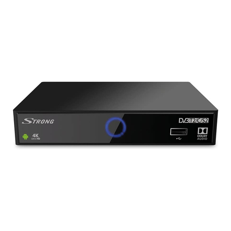
Panasonic TU-DST52 User manual

nasonlc o
HDTV Digital Receiver
Operating Instructions
TM
DDI=-_I
DIGITAL
TU-DST52
ATSC CERTIFIED
DIGITAL TELEVISION
*The presence of the DTV certification mark indicates that this
product will successfully receive digital television transmissions
that conform to any and all of the video formats described in the
ATSC Digital Television Standard.
For product assistance, please call: 1-888-726-2377 TQB2AA0446-1
PRINTED IN USA 21112

The tightning flash with arrow
head within atriangle is
intended to tell the user that
parts inside the product are a
risk of electhc shock to
persons.
The exdamatlen pointwithina
triangleis intendedto tell the
user that important operaUng
and servicinginstructionsare
in the papers with the
appliance.
WARNING: TO REDUCE THE RISK OF FIRE OR ELECTRIC SHOCK, DO
NOT EXPOSE THIS APPARATUS TO RAIN OR MOISTURE.
,_ he Class II insulation symbol (square within a square)
indicates that this product has been evaluated and tested
to comply with Class II insulation requirements.
This product incorporates the following U.S. Patent(s) 5,623,311; 5,999,569; 6,049,651; 6,137,539;
6,266,098; 6,301,299; 6,369,861; 6,384,870; 6,411,337; other U.S. and foreign patents pending.
Read these instructions completely before operating television.
Contents are subject to change without notice or obligation.
Copyright 2002 by MatsushitaEJectricCorporationof America.All rightsreserved.
Unauthorizedcopyinganddistributionisaviolationof law.

IMPORTANT SAFETY INSTRUCTIONS
1. Read these instructions.
2. Keep these instructions.
3. Heed all warnings.
4. Followall instructions.
5. Do not use this apparatus near water.
6. Clean only with dry cloth.
7. Do not block any ventilation openings. Install in accordance with the manufacturer's instructions
8. Do not install near any heat sources such as radiators, heat registers, stoves, or other apparatus (including amplifiers)
that produce heat.
9. Do not defeat the safety purpose of the polarized or grounding type plug Apolarized plug has two blades with one
wider that the other. Agrounding type plug has two blades and a third grounding prong. The wide blade or the third
prong are provided for your safety. If the provided plug does not fit into your outlet, consult an electrician for
replacement of the obsolete outlet.
10. Protect the power cord from being walked on or pinched particularlyat plugs, convenience receptacles,
and the point where the they exit from the apparatus.
11. Only use attachments/accessories specified by the manufacturer.
12. Use only with the cart, stand, tripod, bracket or table specified by the manufacturer, or sold with the
apparatus. When a cart is used, use caution when moving the cart/apparatus combination to avoid
injury from tip-over.
13. Unplug this apparatus during lighting storms or when unused for long periods of time.
14. Refer all servicing to qualified service personal. Servicing is required when the apparatus has been damaged in any
way, such as power-supply cord or plug is damaged, liquid has been spilled or objects have fallen into the apparatus,
the apparatus has been exposed to rain or moisture, does not operate normally, or has been dropped.
FCC INFORMATION
This equipment has been tested and found to comply with the limit for aClass B Digital Device in accordance with the spec-
ifications in Part 15 of FCC Rules. The rules are designed to provide reasonable protection against radio and television
interference in a residential installation. This equipment generates, uses and can radiate radio frequency energy and, if not
installed and used in accordance with the instructions, may cause harmful interference to radio communications. However,
there is no guarantee that interference will not occur in a particular installation.
If this equipment does cause interference to radio or televisions reception (which you can determine by turning the equip-
ment off and on), try to correct the interference by one or more of the following measures.
Reposition or relocate the receiving antenna for the radio or television that is "receiving" the interference.
Change the position of the HDTV Digital receiver with respect to the radio or television equipment that is receiving
interference.
Move the HDTV Digital receiver away from equipment receiving interference.
Plug the HD'I'V Digital receiver into a different wall outlet so the HDTV Digital receiver and equipment receiving the
interference are on different branch circuits.
If these measures do not eliminate interference, please consult your dealer or an experienced radio/television technician
for assistance.
FCC CAUTION:
Pursuant to 47CFR, Part t5.21 of the FCC rules, any changes or modifications to this HDTV DIGITAL RECEIVER
not expressly approved by Matsushita Electric Corporation of America could cause harmful interference and
would void the user's authority to operate this device.
1o

TABLE OF CONTENTS
Table of Contents
Important Safety Instructions ................................... 1
Congratulations ......................................................... 3
Customer Record ...................................................................... 3
Care and Cleaning ..................................................................... 3
Specifications ............................................................................ 3
Installation .................................................................. 4
HD'I'V Digital Receiver Location ................................................ 4
Connecting Cables .................................................................... 4
AC Power Supply Cord .............................................................. 4
Antenna Installation and Orientation ......................................... 4
Antenna /Cable Connection ...................................................... 5
Front and Rear View of the HD'FM
Digital Receiver ........................................................ 6
Front Panel ................................................................................ 6
Rear Panel ................................................................................. 7
Features of the HDTM Digital Receiver ................... 8
Display Format .......................................................................... 8
Format Selection ....................................................................... 8
Aspect Ratio Selection .............................................................. 9
Channel and Program Tuning ................................................. 10
Channel Banner ....................................................................... 10
Getting Started ........................................................ 11
Connect AC Power Cord ......................................................... 11
Connecting the HDTV Digital Receiver to an
HDTV monitor ........................................................................ 11
HDTV Digital Receiver and
NTSC Monitor/Receiver Connection ..................................... 12
HDTV Digital Receiver, NTSC Monitor/Receiver and
VCR/S-VCR connection ........................................................ 13
Connecting the HDrV Digital Receiver to
Dolby Digital decoder ............................................................ 14
Remote Control Operation ..................................... 15
Battery Installation ................................................................... 15
Mode Operational Key Chart .................................................. 16
Programming the Remote ....................................................... 17
Component Codes ................................................................... 18
Special Function Remote Buttons ......................... 20
Roller Guide TMMenu Navigation ............................ 21
Roller Guide TMMenu Icons ..................................... 23
Icon Menus .............................................................................. 23
Start Setup Menu ..................................................... 24
Rollerguide Menu Operations ................................ 25
Set Up...................................................................................... 25
Options ................................................................................... 27
Lock ......................................................................................... 30
Timer ..................................................................................... 35
Troubleshooting Chart ............................................ 37
Limited Warranty ..................................................... 38
Customer Services Directory ................................. 40
Index ......................................................................... 41
20
CONGRA TULA TIONS
Congratulations
Your Panasonic HDIV Digital tuner features state-of-the-art technology for high-quality picture and sound with complete
audio/video output jacks for your home theater system. DTV signals are displayed in either an intedaced or progressive
format, providing a clear, crisp picture. When connected to the HDTV Digital Receiver, your HDTV monitor/receiver can
display high-definition (HDTV) 1080i format and standard definition (SDTV) 480p or 480i format. Your new HDTV Digital
Receiver is designed to give you many years of enjoyment.
Customer Record
The model and serial number of this product are located on the back of the HDTV Digital Receiver. You should note the
model and serial number in the space provided and retain as a permanent record of your purchase. This will aid in
identification in the event of theft or loss. Product registration is available on-line at : www.prodreg.comlpanasonic.
Model
Number
Serial
Number
Care and Cleaning
Set Top Box (Turn HDTV Digital Receiver Off)
{3 ForHDTV Digital Receiver,avoid excessive moistureand wipe dry.DO NOT USEABRASIVE CLEANERS.
{3 Avoid bumping or scraping the HDTV Digital Receiver.
Remote Control
[] Forremotecontrol,usea soft clothdampenedwithwaterora milddetergentsolution.Avoidexcessivemoistureandwipedry.
O Do notusebenzene,thinnerorotherpetroleumbasedproducts.
Specifications
Power Source 120V AC, 60Hz
VHF/UHF- 2-69*
Channel Capability -ATSCIDTV CATV - 1-125"
DigitalAudio Output Dolby Digital Fiber Optic
Video Output Jacks 1Vp-p, 75 Ohm, Phono Jack Type
Audio Output Jacks 0-2.0V RMS 4.7K Ohm
D'rv Output (Y /PB/PR) 75 Ohms, Phono Jack Type
S-VideoOut Jack S-Video (Y-C) Connector
Specifications are subject to change without notice or obligation.
*The digital tuning system allows channel numbers up to 999 to be displayed,
The total channel capability, however, remains as stated.
3@

INSTALLATION
Installation
HDTV Digital Receiver Location
Follow these recommendations before deciding the location of your HDTV Digital Receiver.
[] Avoid excessive sunlight or bright lights, including reflections.
[] Keep away from excessive heat or moisture. Inadequate ventilation may cause internal component failure.
[] Fluorescent lighting may reduce remote cantrol transmitting range.
[] Keep away from magnetic equipment, including motors, fans and external speakers.
Connecting Cables
Component Video cables (Y, PB, PR) are provided for connection to a DTV-Compatible monitor/receiver. Shielded audio
and video cables (not provided) should be used between components. For best results:
[] Use 75-ohm coaxial shielded cables,
[] Use appropriate input and output connectors that match your component connectors.
[] Avoid long cables to minimize interference.
AC Power Supply Cord
CAUTION: TO PREVENT ELECTRIC SHOCK MATCH WIDE BLADE OF PLUG TO WIDE SLOT OF AC OUTLET
AND FULLY INSERT. DO NOT USE A PLUG WITH A RECEPTACLE OR OTHER OUTLET UNLESS THE BLADE ,_/_
CAN BE FULLY INSERTED TO PREVENT BLADE EXPOSURE. Polarized plug
PROTECT POWER CORDS FROM BEING WALKED ON, ROLLED OVER, CRIMPED, BENT OR PINCHED,
PARTICULARLY AT PLUGS, CONVENIENCE RECEPTACLES, AND THE POINT WHERE THEY EXIT FROM THE APPARATUS.
Antenna Installation and Orientation
Yagi
Log Periodic
Reflector
In many areas, an indoor antenna can be used to receive Drv signals. Certain condition, however,
may create a situation where an outdoor antenna is required. Tall buildings, large metal objects
(e.g., a water tower) or hills may block the line-of-sight to the TV station and interfere with DTV
signal reception. Keep the following in mind when installing and orienting your outdoor antenna.
For addition information about antennas, see the Consumer Electronics manufacturing
Association (CEMA) website at: www.cemacity.org or ask your local dealer.
[] Choose an antenna with directional receiving characteristics such as a Yagi, log periodic, or reflector
antenna. Avoid loop, wire bowtie, rabbit-ear and omni-directional antennas.
[] Use good grade 75 Ohm coax (round) cable to connect the antenna to the HDTV Digital Receiver. Do not
use 300 Ohm flat twin-lead cable.
[] Place the antenna away from large metal objects. If using an indoor antenna, remember that aluminum
siding and foil-covered insulation can greatly reduce the signal strength inside your house.
[] Point the antenna in the direction of the TV station Allow a 4-6 second delay in tuning. Watch for a
program to appear on the "iV. If the on-screen indicator is "Poor Signal Quality" or if a program comes
and goes, try a slightly different position for the antenna. Slowly raising or lowering the antenna by a few
feet may help.
[3 Avoid standing in front of the antenna while adjusting its position. Move a few feet to the rear to avoid
changing the signal characteristics.
[3 If you are located in an area serviced by two (2) different DTV stations in different directions, you may
need an antenna rotator to receive signals from both stations.
40

INSTALLATION
Antenna ICable Connection
For proper reception, antenna or cable connection is required.
Antenna Connection
For proper reception of DTV channels, a directional antenna is required (see previous page). For best reception, an
outdoor antenna is recommended.
Procedure
Conned the antenna cable from your antenna.
OSelect ANTENNA, in the Roller Guide SET UP Menu under Input.
Incoming Cablefrom
Home Antenna
75 Ohm ATSC/DTV input
on back of HDTV Digital Receiver
Cable Connection
Before connecting your Cable to the HDFV Digital Receiver, contact your local cable provider and ask the following
questions: Is DTV availablethroughyourcable service?
Doyou needaseparatecable boxto receiveD'IV signals?
Procedure
C3 Connectthe cablewire providedbyyourlocalcable provider.
OSelectCABLEinthe RollerGuide Set Up menuunderInput.
Incoming Cable from
Cable Company
75 OhmATSC/DTV input
on backof HDTV DigitalReceiver
Note: The Panasonic HD TV Digital Receiver is able to receive D73/signals from your local cable provider only if they are transmitted
in the 8VSB modulation format approved by the FCC for DTV transmission, Also, your cable provider may elect to transmit in
the 8VSB format for only a limited period of time.
50

FRONT AND REAR VIEW OF THE HDTV DIGITAL RECEIVER
Front and Rear View of the HDTV Digital Receiver
Front Panel
SIGNAL QUALITY
,
--[2ZI
POWER F..XIT
©
\ \
ACTION
©
,/
[]
I
Infrared sensor
Panasonic
HD HYBRID SD
'U
\
HDTV DIGITAL RECEIVER
\\
_T_
.m.O,T_./
,/'*
FEATURES DESCRIPTION
(_) POWER Turns the HDTV Digital Receiver On or Off.
Signal Strength Indicator LED (tri-color):
SIGNAL QUALITY Red: Unlocked Condition
Yellow: Locked condition with poor signal strength.
Green: Locked condition with adequate signal strength.
(_ MENU Press to display and exit Roller Guide Menu system.
(_ INFO Press to display the Channel Banner or other on-screen displays.
(_ ACTION Press to enter the selection fi-om the menu.
(_ EXIT Exit Menus.
(_ Navigation Buttons Press these Navigation buttons to move the highlight left or right,
(_) Navigation Buttons Press to change CH Up /Down or to move the highlight up or down in Roller Guide
menus.
(_ HD, HYBRID, SB Video Format Indicator LEDs.
INFO + ACTION Press these two buttons together to change Video Format.
*Manufactured under license from Dolby Laboratories.
"Dolby", "Pro Logic", and the double-D symbol are trademarks of Dolby Laboratories.
60

RearPanel
FRONT AND REAR VIEW OF THE HDTV DIGITAL RECEIVER
Antenna In Jack Service Data Injack (used only by Servicer)
DIGITAL
,. Y@ v®v®
,+® IR®t.®o
(_ [] DIGITALW OUTI VIDEO -NTSCOUT-VIDEO2
Dolby Digital put (Y, Pb, Pr) NTSC AN Outputs
Connection (Optical)
/
AC IN
AC INPUT JACK
ANTENNAIN Use to connect the antenna to the HDTV DIGITAL RECEIVER.
DATA IN Port used to input service related data. (For service center use only)
DOLBY DIGITAL OUT
(OPTICAL)
Optical Digital Audio Out connection to Dolby Digital decoder.
DIGITAL TV OUTPUT Component Video Output connection to a HDTV monitor.
NTSC OUTPUT AudioNideo connections to a Conventional TV or a VCR.
S_IDEO S-VIDEO out connection for an NTSC monitor or a S-VCR. This connection
provides better video with NTSC monitor,
AC INPUT AC inputjack.
Note: Use the L and R audi_ _ut jacks _f V_DE_1t_gether with the D_G_TAL TV _UTjacks when c_nnecting the
HDTV Digital Receiver to a HDTV monitor or receiver. (refer to page 11 for connection diagram)
Digital TV Out
jacks connected __
to component
input of HDTV
monitor.
L& R audio
out jacks
"___connected to
HDTV monitor
audio in jacks.
70

FEATURES OF THE HD TV DIGITAL RECEIVER
Features of the HDTV Digital Receiver
Display Format
The HDTV Digital Receiver converts all eighteen (18) ATSC display formats available in D'IV into viewable programming,
The display formats are variations on the four (4) formats 1080i, 720p, 480p and 480i. The following table shows the four
(4) formats, their resolutions and aspect ratios.
DTV Format Resolution Aspect Ratio
1080i High Definition 16:9
720p
480p
480i Standard Definition 16:9 or 4:3
Format Selection
The HDTV Digital Receiver allows you to choose a display format based on the capability of your TV or monitor. To select
the appropriate format, use the VIDEO OUT button on the remote control.
HD Mode
If your "IV is capable of displaying 1080i high definition signal, set the video out format to HD mode. 1080i, 720p, 480p and
480i signals are outputted as 1080i.
Input Format
(from antenna/cable) Output Format to "IV
1080i
720p 1080i
480p 1080i
480i
Hybrid Mode
In the Hybrid mode, 1080i and 720p signals are outputted as 1080i, 480p is outputted as 480p and 480i is outputted as
480L
Input Format
(from antenna/cable) Output Format to TV
1080i
720p 1080i
480p 480p
480i 480i
SD Mode
In the SD mode, all formats are outputtedas 480i. If your TV capable of displaying NTSC formats only, then set the Video
Out mode to SD.
Input Format
(from antenna/cable) Output Format to "IV
1080i
720p 480i
480p
480_ 480i
8Q

FEATURES OF THE HDTV DIGITAL RECEIVER
Aspect Ratio Selection
The HD'I-V Digital Receiver changes the normal aspect ratio (picture display shape) in response to the source signal and
monitor format of your "IV. You can also change the aspect ratio for your personal viewing preference. To select an aspect
ratio, press the ASPECT button on your remote control and the HD'I'V Digital Receiver will cycle to the next available
aspect ratio choice, The following table shows the available aspect ratios.
Source Signal 16:9 4:3
16:9 FULL (No Scaling) FULL - ZOOM -LE'N'ERBOX
4:3 FULL-SIDEBAR FULL (No Scaling)
Full Aspect
16:9 or 4:3 picture will be displayed in the center of the viewing screen at full screen width and height.
Zoom Aspect (4:3 Monitor receiving 16:9 source signal)
The picture wilt be expanded uniformly (width and height) to fill the viewing screen. The picture will be cropped, either horizontally or
vertically to fit the viewing screen. The cropped portion of the original picturewill be lost from view.
Letterbox Aspect
Video formats with aspect ratios greater than 16:9 will be displayed at the proper width, so no video information is lost. Bars will appear
above and below the picture.
Sidebar Aspect
4:3 picture will be viewed on a widescreen TV with vertical bars on both sides of the picture.
Aspect Ratio Formats
The table below shows the different aspect ratios available with a 16:9 or a 4:3 format monitors.
ASPECT RATIO FORMATS
Source
Signal
16
T
The 16:9 and 4:3 pictures
represent the incoming
source signals received by
the HDTV Digital Receiver.
FULL SIDEBAR
-
FULL ZOOM LET£ERBOX
t
These pictures showthedifferent aspect ratios
availablewitha 16:9 monitor format.
The top picture shows the 16:9 monitor
format available when the HDTV Digital
Receiverreceives a 16:9 source signal.
The bottom pictures show the 16:9 monitor
formats available when the HDTV Digital
Receiver receives a 4:3 source signal.
1
These pictures show the differentaspectratios
availablewitha 4:3 monitorformat,
The top pictures show the 4:3 monitor
formats available when the HDTV Digital
Receiverreceivesa 16:9source signal.
The bottom picture shows the 4:3 monitor
format available when the HDTV Digital
Receiverreceives a 4:3 source signal.
90

FEATURES OF THE HDTV DIGITAL RECEIVER
Channel and Program Tuning
Channel and program tuning in digital television is very different from current conventional television. In DTV, up to six (6) multiple
programs can exist within asingle 6 Mhz channel, These channels behave as sub-channels within the single channel. When
tuning to a channel, the HDTV Digital Receiver will also tune to a program. The HDTV Digital Receiver will indicate the channel
and program through the on-screen Channel Banner display.
Channel and program tuning
The HDTV Digital Receiver allows channel and program selection in the following ways:
[] Direct tuning (0 ~ 9 keys) -Using the numeric keys on the Remote Control to directly inputthe Channel number. Ifnecessary use the
PROG button to enter the program number.
[] Channel Up/Down Tuning (A or •buttons) -Tunes to the next or previous available channel or program.
[] Rapid Tuning (R-TUNE) -Switches between the last two channels or programs.
Direct Tuning Method
Follow the procedure below to directly enter the channel number using the Remote Control,
Procedure
[] Press the numedc keys on the Remote Control to enter the Channel number,
[] if your channel contains more than one program, press the PROG button and enter the program # (1, 2, 3 etc.) using the numeric
keys.
ChannelBanner
The basic Channel Banner will display channel number, and station identification.
Complete Channel Banner in DTV mode
When you press the INFO button, the complete channel banner is displayed, The channel banner willdisplay channel number,
stationidentificationtime or day and ratings information. In addition,the banner will displayAdd Channel and Delete Channel
buttons.
Channel # and
program #. -- display
Closed Caption rAdd Channel ]
Indication Add or Delete Channel buttons.
Ratings
Indication
Add Channel or Delete Channel feature
This feature lets you delete channels from memory or add channels to memory.
Procedure
OTune the desired channel to be added or deleted,
OPress the INFO button to display the Channel Banner.
OHighlight Add Channel or Delete Channel button using 41or •
C3 Press ACTION button to execute your choice.
Unavailable Channel selection
The unavailable channel selection screen is displayed when you select an unavailable channel. The following is alist of some
possible situations where an unavailable channel selection may occur.
[3 Tuning a channel that is not transmitting any programs
Tuning a channel that stopped broadcasting programs.
[] The signal strength of the RF signal is insufficient to obtain consistent error free data.
[] Tuning achannel that is locked
Following are some of the on-screen messages that will be displayed when the above conditions are encountered,
10e

GETTING STARTED
Getting Started
Connect the AC power cord
Plug in the supplied AC cord to the AC IN jack of the HDTV Digital Receiver and plug-in the other end to the wall socket. Do
not turn on any devices until you have finished all necessary connections.
Connecting the HDTV Digital Receiver to an HDTV monitor
Follow the diagram below to connect the HDTV Digital Receiver to an HDrV Monitor/Receiver.
Incoming signal
from antenna or
cable @
DATA
IN
TERMINALS ON BACK OF HDTV MONITOR
I @ -v,oEo
® ® V,D O
®
®
VIDEO I HTSC OUT-VtDE;O
HDTV DIGITAL RECEWER
Note: Component Video
Cables are included.
AC IN
Procedure
[] Connect video cables from the DIGITAL TV OUTPUT (Y, PB, PR) jacks on the HDTV Digital Receiver to the Y, PB, PR Digital TV input
jacks on the HDTV monitor.
O Select the Video Format to match the digital display capability of your monitor.
O Connect audio cables from the left and right audio output jacks of VIDEO 1to the input jacks on the TV. For digital audio, connect the
Dolby Digital output to an Dolby Digital amplifier. (Please see the diagram on page 14).
Stereo Outputs
The stereo audio outputs are Dolby Surround compatible. You can connect a Dolby Surround Pro Logic decoder (not
included) to the stereo audio outputs.
11e

GETTING STARTED
HDTV Digital Receiver and NTSC Monitor/Receiver connection
Follow this diagram when connecting your HD'I'V Digital Receiver to a NTSC Monitor/Receiver.
Note: Cables not included.
Inc_mlng signal DOt.BY
ardBnna or D_^ ,
cable
I _.
IvQ°v,oEo
I INPUT1INPUT2
\ \ \
menTALwOUTI_o _-msc c_T-_oeo 21
TERMINALS ON BACK OF
NTSC MONITOR /RECEIVER
AC IN
HDTV DIGITAL RECEIVER
Procedure
0Connect the AN output (VIDEO1 or VIDEO 2) to the,AN Input of the NTSC monitor/receiver.
[] If your monitor has S-VIDEO input, connect the S-VIDEO output of the HDTV Digital Receiver to the S-VIDEO in of the monitor/
receiver.This connection will give you better video signal.
Select SD format mode on the HDTV Digital Receiver.
Note: If both Video and S-Video are connected to the monitor, S-VIDEO will override the composite video connection.
12=,

HDTV Digital Receiver, NTSC Monitor and VCR IS-VCR connection
Use this diagram to connect the HDTV Digital Receiver with a NTSC monitor and a VCR /S-VCR.
VCR/S-VCR
TERMINALS ON BACK OF MONITOR I_ _ O]
GETTING STARTED
Incoming Signal
horn antenna or
cable
(_
DIGITAL
AUDIO L
DATA :)IGITAL TV OUT VIDEO 1-NTSC OUT-VIDEO 2
_N (OPTICAL)
HDTV DIGITAL RECEIVER
Procedure
[] Connect the VIDEO 1 or VIDEO 2 output to VCR's AV IN JACK. If you have a S-VCR, connect the S-VIDEO output from the HDTV
Digital Receiver to the S-VIDEO input of the S-VCR.
[] Connect the AV out to the video input of your NTSC monitor/Receiver. If your monitor has S-VIDEO, connect the S-VIDEO out from
the S-VCR to the monitor.
[] Select HDTV Digital Receiver output to SD mode.
13e

GETTING STARTED
Connecting the HDTV Digital Receiver to Dolby Digital decoder
Use the following diagram to connect Dolby Digital output of your HDTV Digital Receiver to a Dolby Digital decoder.
Digital Audio Out (Dolby Digital)
Dolby Digital 5.1 channel surround sound delivers digital-quality sound. Dolby Digital provides five discrete full-bandwidth
channels for front left, front right, center, surround left and surround right, plus a LFE (Low Frequency Effect) subwoofer
channel. For a full Home Theater sound experience, an external Dolby Digital decoder and a multichannel amplifier must
be connected to the HDTV Digital Receiver.
DolbyDigital
Decoder
Note:Cables notincluded.
F
Optical Cable _
f%%..,
In_nlflg signal
f_om antenna or
cable
DATA (OPTICAL)
IN
I- 6 - channel Amplifier
I&Speakers
I
L
tDIGITAL I
7I AUDIO IN E
I]_ (DOLBY DIGITAL) I t
HD'FV Digital Receiver
Pb i S-VIDEO
P, :®
#
I -o;TM
DTV Terminals On
Back of TV
o]
AC IN
Procedure
{3 Connect the Digital Audio cable from the Digital Audio Out connection on the HDTV Digital Receiver to the Digital Audio In
connection on the Dolby Digital decoder.
D If using a HDTV monitor, use component video cables to connect the TV to the HDTV Digital Receiver
0If using a conventional TV use either composite video or S-Video cable to connect the TV to the HDTV Digital Receive[
14e

Remote Control Operation
REMOTE CONTROL OPERATION
IPress to tom ON and OFF.
Press to select device operation.
Note: Press DTV to controlHDTVDigital Receiver.
[I Press to accsss m:_CuosTl_:ubmenus" 1
MENU
O
Press to access Rollerguide menus.
Press to exit menus,
Press to se ect TV_mode.
®@®
®®®
®®®
@
Press numeric keypad to select any channel.
R-_NE
Press to switch to previously viewed
II channel or video mode.
EUR7613Z50
Battery Installation
Use two AA batteries:
Remove battery cover by pressing down on the marking on the battery
cover and sliding it back
Install batteries matching (+) and (-) polarity signs
Replace the battery cover.
Note: Incorrect installation can cause battery leakage and corrosion that
will damage the Remote Control.
SAP
Press to cycle through multiple audio tracks (ff
available) In DTV mode or select audio modes
In TV mode.
• VOL VOLI
Press to navigate in menus and adjust
volume in TV mode.
Press to navigate in menus and select next
or previous channel.
INFO
O
Press to display time, channel and other
information.
LPrsssto select TV or VCR.
I %c,
I Select picture shape to match signal and
Lmonitorformat (D'rV only).
Press to enter the pr_ number in a
channe number.
REW PLAY FF
VIDEO OUT*
PAUSE STOP REC
MUTE r-"TV VOL--]
Component function buttons
*Press to switch Video Output formats in
JDTV mode.
Precautions
Replace batteries in pairs.
Do not mix battery types (zinc carbon
with alkaline)
Do not recharge, heat, short-circuit,
disassemble, or burn batteries
15e

REMOTE CONTROL OPERA TION
Mode Operational Key Chart
This chart defines the keys that are operational in the selected component modes (DTV, l'V, VCR or DVD) after
VCR POWER DVD POWER
programming (if needed).
KEY NAME
POWER
SAP
CH •
CH •
VOL •
•VOL
ACTION
MENU
INFO
EXIT
TVNIDEO
TVNCR
ASPECT
R-TUNE
PROG
1
2
3
4
5
6
7
8
9
0
<<REW
PLAY
FF >>
PAUSE
STOP
VIDEO OUT
RECORD
MUTE
FTV VOL--I
DBS POWER
DTV AUDIO TRACK
NAVIGATION UP
NAVIGATION DOWN
DTV NAV RIGHT
DTV NAV LEFT
DTV ACTION
DTV ROLLERGUIDE
MENU
DTV CHAN BANNER
EYJT MENUS
TV INPUT SELECTION
DTV ASPECT
PREVIOUS DTV CHAN
D1V PROG/-
DIGIT 1
DIGIT 2
DIGIT 3
DIGIT 4
DIGIT 5
DIGIT 6
DIGIT 7
DIGIT 8
DIGIT 9
DIGIT 0
DTV VIDEO FORMAT
SELECTION
TV AUDIO MUTE
TV pOWER
SELECTS AUDIO MODE*
(STEREO, SAP OR MONO)
CHANNEL UP
CHANNEL DOWN
TV VOL +
TV VOL -
TV MENU IENTER
TV DiSPlAy
TV INPUT SELECTION
TV VCRSWITCH
PREVIOUS CHAN
OR VIDEO MODE
DIGIT 1
DIGIT Z
DIGIT 3
DIGIT 4
DIGIT 5
DIGIT 6
DIGIT 7
DIGIT 8
DIGIT 9
DIGIT 0
VCR REWIND
VCR pLAy
VCR FF
VCR PAUSE
VCR STOP
VCR RECORD
TV AUDIO MUTE
VCR CBAN UP
VCR CHAN DOWN
TVVOL ÷
TV VOL -
ON-SCREEN VCR
DISPLAY
TV INPUT SELECTION
TVNCR SWITCH
VCR REWIND
VCR pLAY
VCR FF
VCR PAUSE
VCR STOP
VCR RECORD
TV AUDIO MUTE
TV VOL UP or DOWN TV VOL UP or DOWN TV VOL UP or DOWN
NEXT CHAPTER
PRE_OUS CHAPTER
NAVIGATIONRIGHT
NAVIGATIONLEFT
DVD DISPLAY
TV INPUT SELECTION
SKIP /SEARCH REVERSE
DVD PlAY
SKIP ISEARCH FF
DVD STILL
DVD STOP
TV AUDIO MUTE
"rvVOL UPor DOWN
*This feature functions only with selected Panasonic televisions.
16e

REMOTE CONTROL OPERATION
Programming The Remote
The Universal Remote Control can be programmed to operate many manufacturers' components, using the component
function buttons for "I'V, VCR or DVD. Follow the procedures for programming your Remote Control with or without a code
for the component. Default Modes For Remote Control
DTV
TV
VCR
DVD
Determine the manufacturer of the component and look in the table for the code.
Programming With a Code
Procedure
Confirm that the external component is plugged in and operating.
Turn the component off.
A_ON and OPress the Remote Control together, for at least 5 seconds.
Press appropriate component button on the Remote Control "IV,VCR or DVD.
Enter the 3-digitcomponent code usingthe Remote Control numedc keypad (0 - 9 buttons).
Press the Remote Control Oto test the component. Ifthe procedure was successful, the component will turn on
ith the Remote Control, repeat
• (Some brands have multiple/
/
IIf an incorrect cede is entered, or if the procedure takes longer than /
130 seconds, the programming will fail. J
Programming Without A Code
This procedure searches all codes and is called the "sequence method"
Confirm that the external component is plugged in and on.
Turn the component off
ACTION
Press the Remote Control O and _together, for at least 5 seconds.
Press appropriate component button on the Remote Control.
Press VOL • to move forward to the next code. Press • VOL to move backward.
Press the Remote Control _--_ to test the component. Ifthe procedure was successful, the component will turn on.
Note: Repeat the above steps until the component code is found. It may take many attempts before the correct code
is found.
ACTION
After the code is found, press O to store the code.
17e

REMOTE CONTROL OPERATION
Component Codes
The Universal Remote Control is capable of operating many component brands after entering a code. Some components
may not operate because the codes are not available due to limited memory. The Universal Remote Control does not
control all features found in each model.
TV VCR DVD
rsm =
Admiral 112, 124, 125
Alwa 138, 142, 143
Akai 104
AOC 105
iBell & Howell 124, 126, 178
3roksonic 104, 105, 144, 180
3entudon 105
CIS Hotel 199
3oltina 203
3oronad 164
!Craig 108, 109, 110
3rosley 115
3urtis Mathes 104, 107, 110
Daewoo 104, 106, 135, 196
:Emerson 104, 108, 109, 110,
120, 133, 134, 180
Fisher 111
=ujitsu 139, 156, 157, 160
--unai 136, 137, 140, 141,
146, 147, 155
3E 101,104, 112, 132
Goldstar 104, 105, 165
-litachi 104, 113, 183
Inteq 126, 127
i
!JC Penny 104, 112
; 114, 158, 159, 167,
iJr C184
KTV 104, 110, 166
LXl 104, 105, 107, 111,
112, 115
Magnasonic 178
104, 105, 115, 116,
Magnavox 129, 168
Marantz. 117
Memorex 178
MGA 104, 105
Mitsubishi 104, 105, 117, 124,
172
MTC 101,103
National 100, 101,102, 151
NEC 104, 105
Orion 128
Panasonic 100, 101,102, 151,
193, 200, 201
Philco 104, 115
Philips 115
Pioneer 101,107, 118
Portland 104
Prism 101
Proscan 104, 112, 119, 121,
122, 185
Quasar 101,103
Radioshack 105, 110, 112, 117
104, 112, 119, 121,
RCA 122, 130, 131,132,
161,162, 163, 169,
186, 202
Samsung 104, 105, 123, 170,
203
Sanyo 111,149, 152, 153,
154, 197
Scott 105, 110
Sears 104, 105, 107, 111,
112, 115
Sharp 120, 124, 150, 187
Signature2000 124, 126
Sony 125, 188, 192
Sylvania 104, 105, 115
Symphonic 110, 171
Technics 100
Toshiba 107, 124, 189
Vidtech 104, 105, 113
Wards 104, 105, 120
Zenith 126, 127, 144, 190
AJwa 123
Apex 120
Denon 100, 117
Ferguson 101
Funai 118, 132
Hitachi 111
JVC 109
Kenwood 115, 129
Konka 119
Mitsabishi 105
Nordmende 101
Onkyo 121
Oritron 124
Panasonic 160
Philips 103, 116
Pioneer 102
Raite 113
RCA 101,106
Saba 101
Sampo 114
Samsung 110
Sharp 108
SMC 125
Sony 104, 126, 127, 128
Sylvania 118, 132,
Technics 100
Thomson 101
Toshiba 103
Vialta 131
V_ve 122
Yamaha 100, 130
Zenith 107, 112
18e
Table of contents
Other Panasonic TV Receiver manuals

Panasonic
Panasonic CT-20G5C User manual

Panasonic
Panasonic TU-HDS20 User manual

Panasonic
Panasonic TU-HDS20 User manual

Panasonic
Panasonic TU-PTA100E User manual

Panasonic
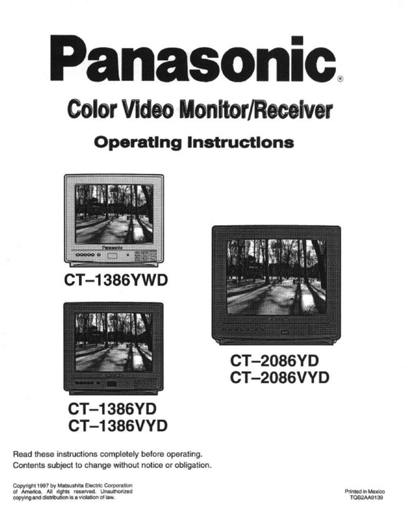
Panasonic CT1386YD - 13" MONITOR W/O TUNER User manual

Panasonic
Panasonic CT-G2937X User manual

Panasonic
Panasonic TU-SZT105A User manual

Panasonic
Panasonic CT-27G14D User manual

Panasonic
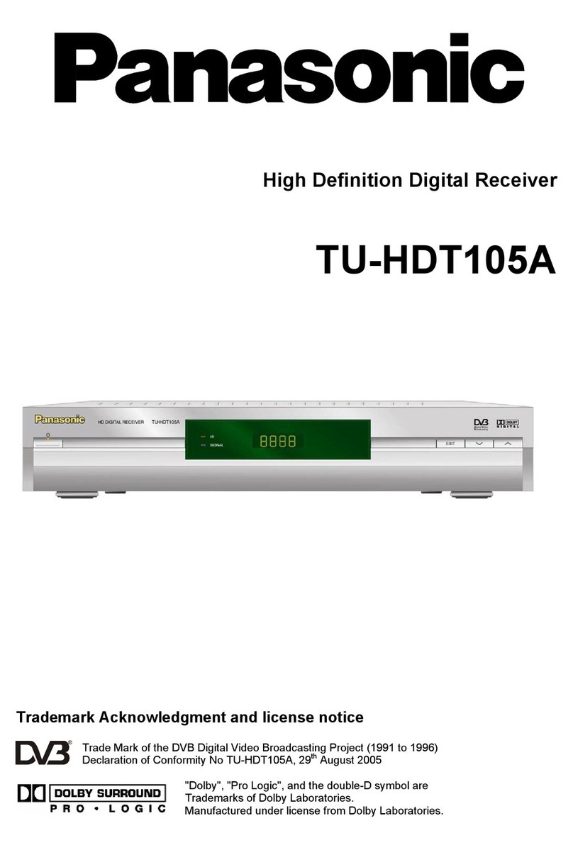
Panasonic TU-HDT105A User manual

Panasonic
Panasonic CT-13R18C User manual