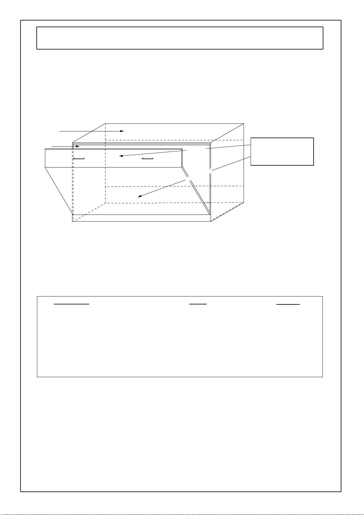
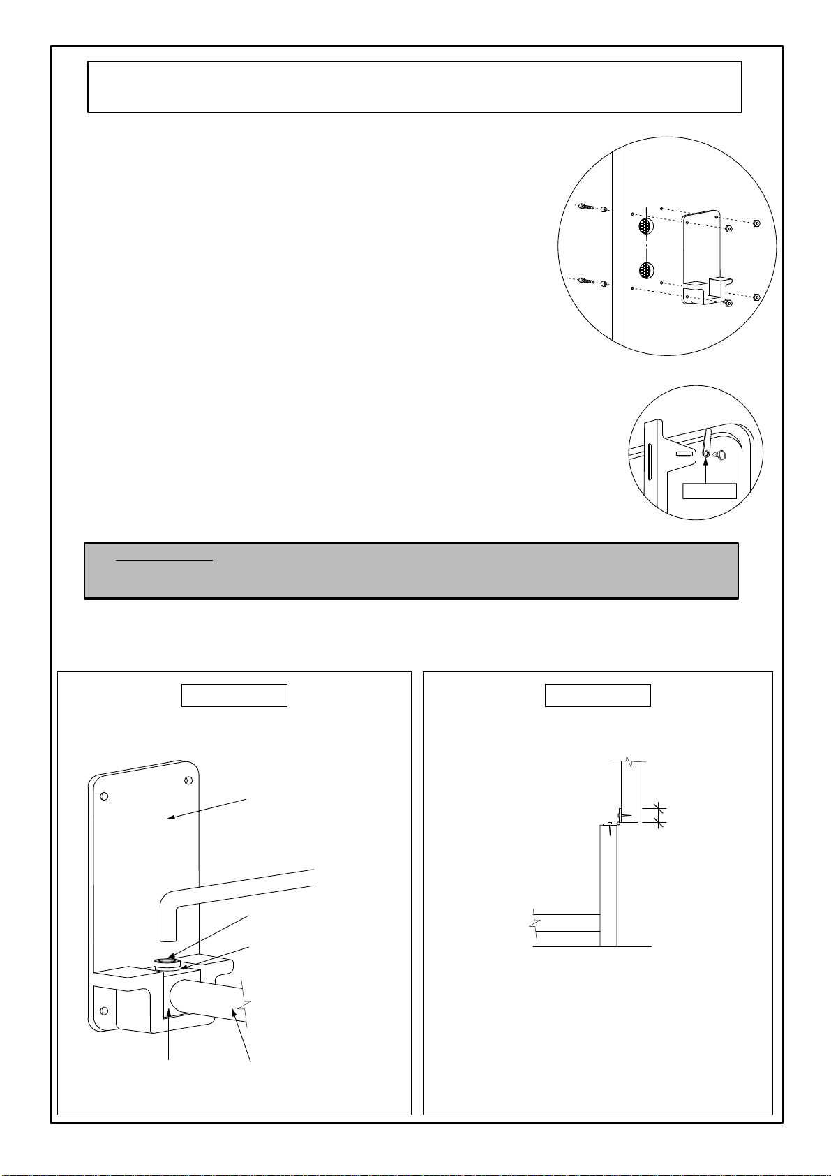
Skirting
Board
Wall
Cut
skirting recess
before
pushing cabinet
against
the
wall
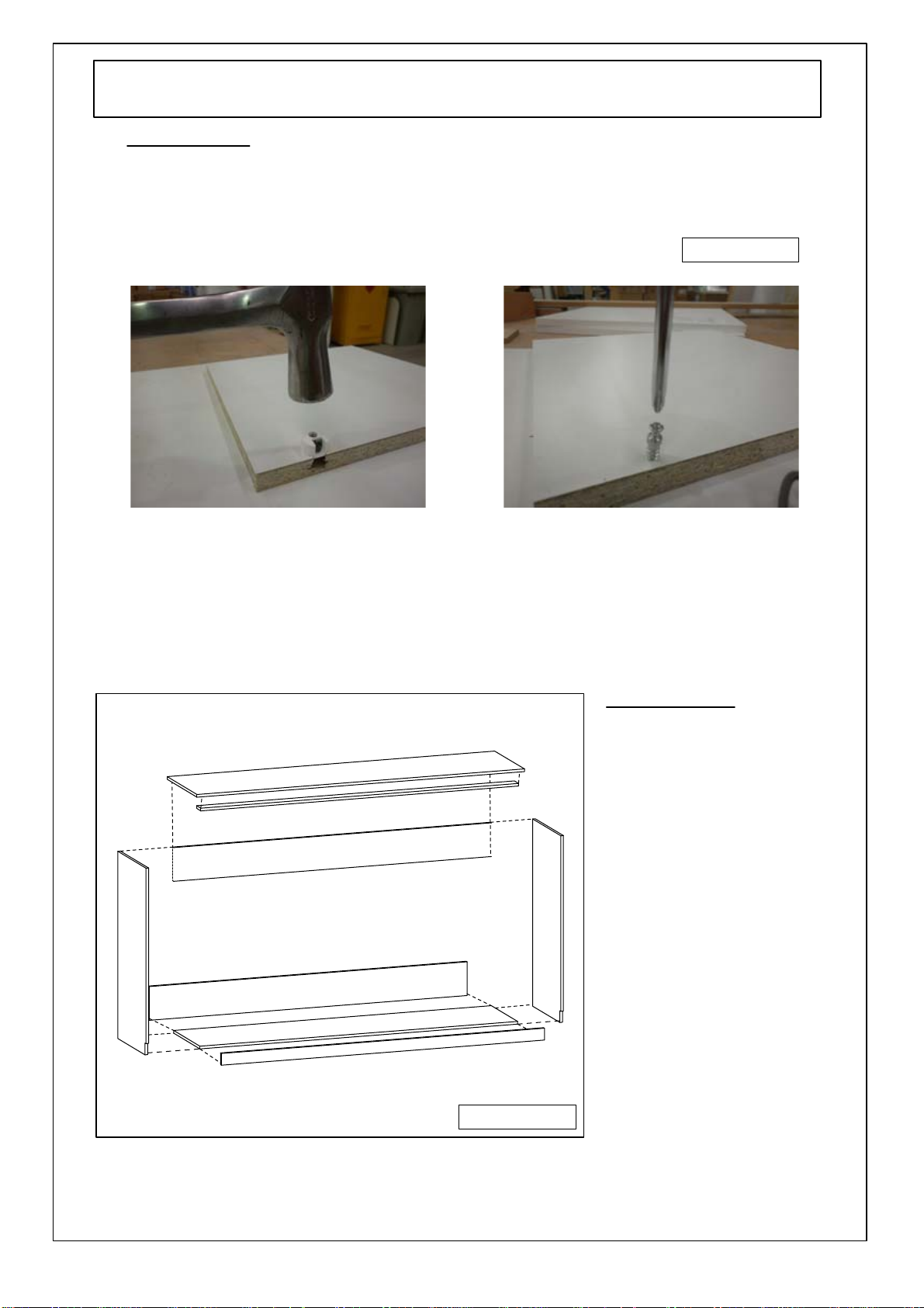
End
Panel
Front
Panel
Base
Panel
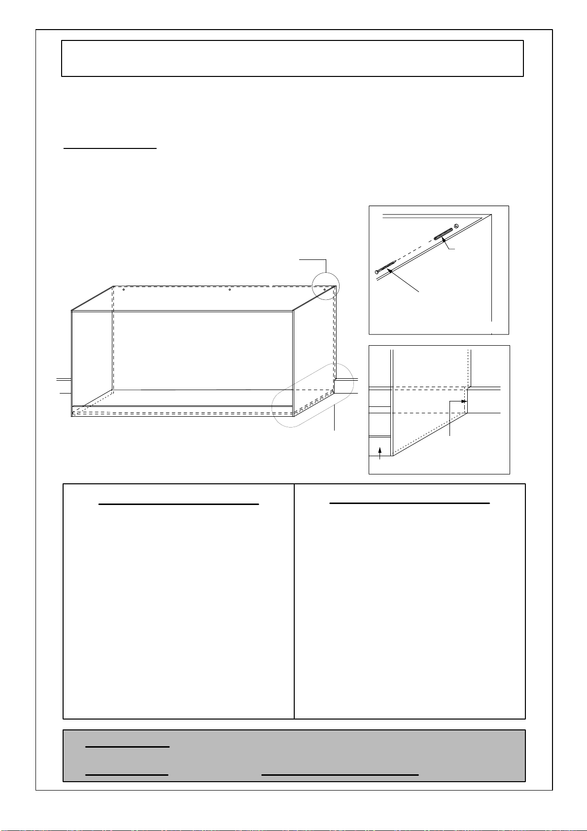
DETAIL
B
Fastening to wall
DETAIL
A
Wall
plugs
Refer
to
detail
B
Refer
to
detail
A
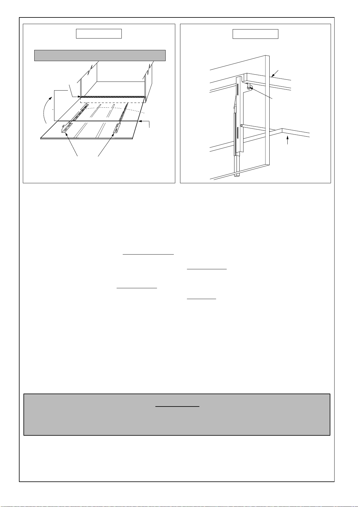
4.
Step2
-
Fixing
Cabinet
To
Wall
*
Lay
cabinet
face
down
with
bottom
facing
the
wall.
*
To
ensure
the
cabinet
is
flush
against the wall when upright, it
may
be
necessary to cut a recess
into
bottom of
left
and
right hand
end
of
cabinet.
*
Place
cabinet
into
position
against
the
wall
and,
using
a
spirit
level
against
either
the
right
or
left
hand
end
and
the
top,
find
the
correct
vertical
and
horizontal
position.
Mark
this
position
on
the
wall
with
a
pencil.
PLEASE NOTE
As
there
is
a
lot
of
tension
in
the
Wallbed
when
in
the open
position,
it
is
very
important
that
the
cabinet
is
securely fixed
to
the wall.
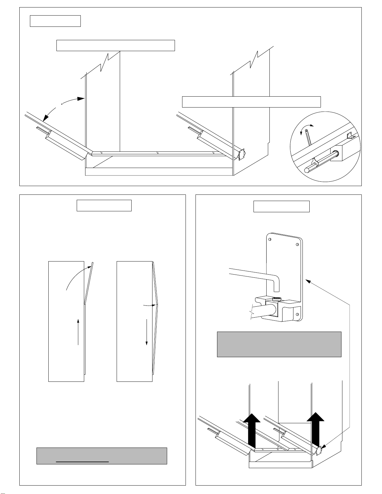
IMPORTANT
NOTE:
Before
moving
cabinet
upright,
ensure
all
cams
are
tightened
securely.
FASTENING
OPTIONS
1
(for
gyprock,
fibro
or
timber
walls)
FASTENING
OPTIONS
2
*
Ensure
cabinet
is
in
correct
vertical
position.
Drill
holes
in
top
of
back
panel
at
top
in
appropriate
position.
*
Using
a
65mm
masonry
bit,
drill
holes
into
wall
and
insert
wall
plugs
supplied.(see
above)
*
Move
cabinet
back
into
place
against
wall.
*
Fix
top
back
panel
to
wall
using
61mm
screws.
Put
on
cover
caps.
(for
brick/masonry
walls)
*
Ensure
cabinet
is
in
correct
position.
*
Locate
wall
studs
*
Drill
holes
in
top
of
back
panel
at top
in
correspording
positions
to
wall
studs.
*
Using
65mm
screws,
screw
cabinet
thru
holes
in
top
of
back
panel
into
studs.
Put
on
cover
caps