Skirting
Board
Wall
Cut
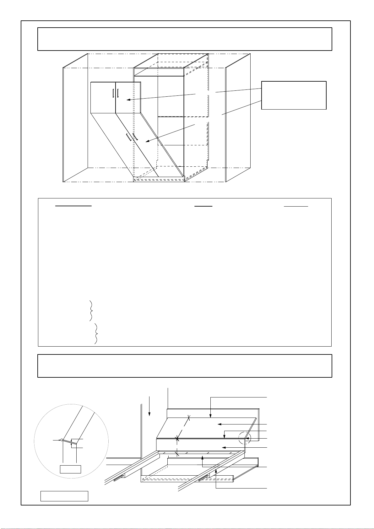
skirting recess
before
pushing cabinet
against
the
wall
End
Panel
Front
Panel
DETAIL
B
Fastening
with
angle
brackets
DETAIL
A
Wall
plugs
Refer
to
detail
B
Refer
to
detail
A
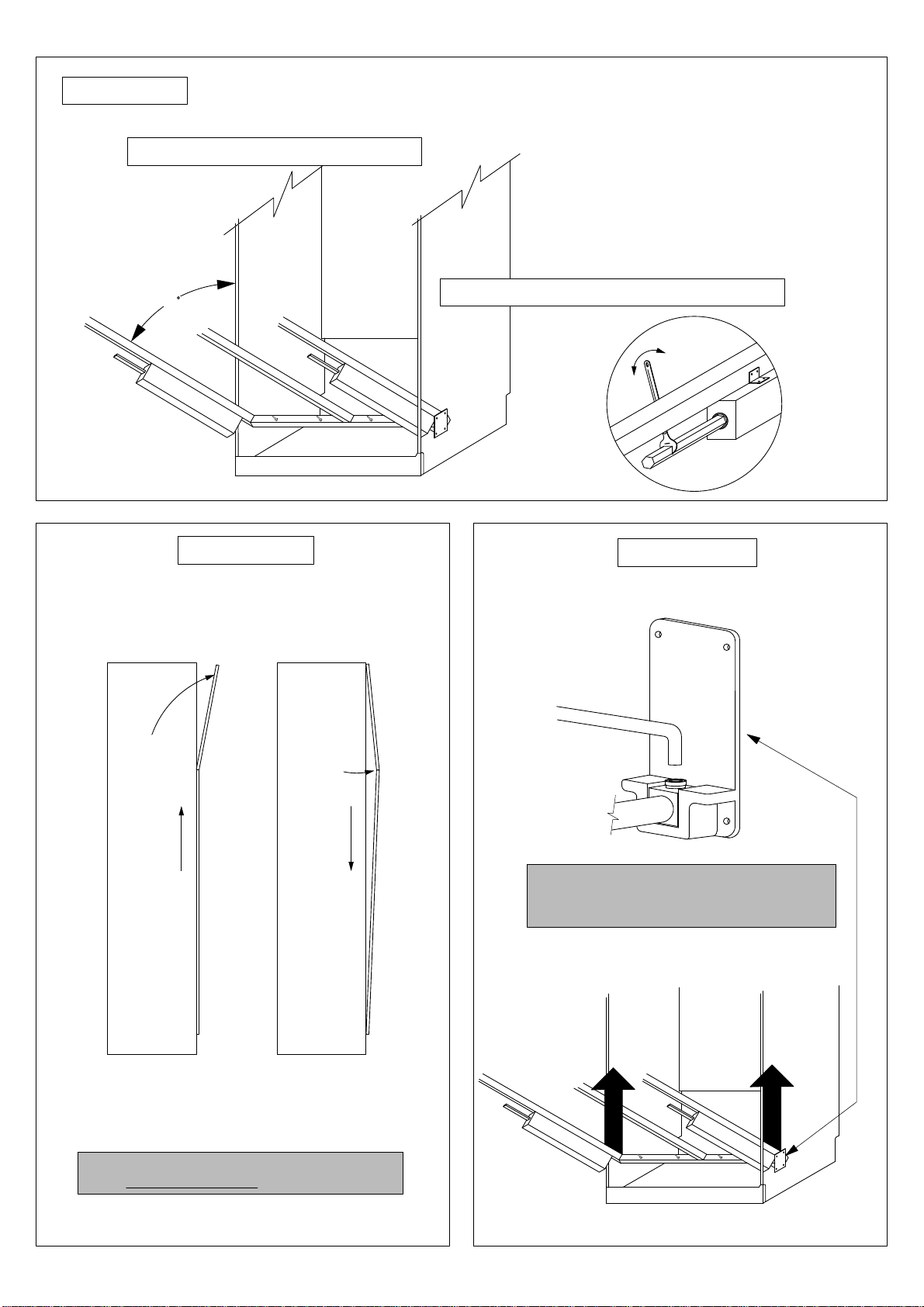
4.
Step2
-
Fixing
Cabinet
To
Wall
*
Lay
cabinet
face
down
with
bottom
facing
the
wall.
*
To
ensure
the
cabinet
is
flush
against the wall when upright, it
may
be
necessary to cut a larger recess
into
bottom of
left
and
right hand
end
of
cabinet
to go
over
skirting.
(refer
to
detail
B)
*
Lift
cabinet
at
top,
pushing
towards
wall,
being
careful
to
have
sufficient
ceiling
clearance.
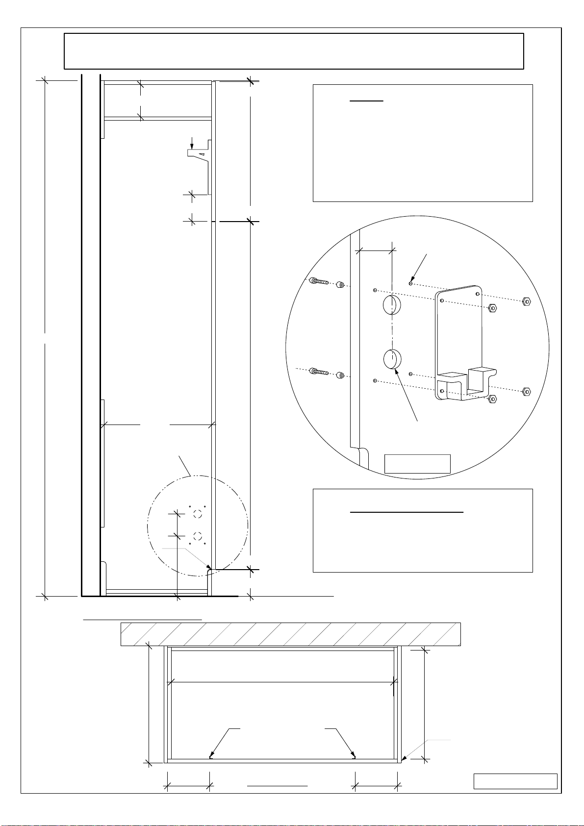
*
Place
cabinet
into
position
against
the
wall
and,
using
a
spirit
level
against
either
the
right
or
left
hand
end
and
the
top,
find
the
correct
vertical
and
horizontal
position.
Mark
this
position
on
the
wall
with
a
pencil.
PLEASE NOTE
As
there
is
a
lot
of
tension
in
the
Wallbed
when
in
the open
position,
it
is
very
important
that
the
cabinet
is
securely fixed
to
the wall.
IMPORTANT
NOTE:
Before
moving
cabinet
upright,
ensure
all
cams
are
tightened
securely.
*
Locate
wall
studs
and
mark
clearly
with
pencil.
*
Sit
angle
brackets
in
cabinet
top,
flush
with
top
and
back
edge
and
against
the
wall
studs.
Ensure
that
the
twin
hole
side
of
bracket
is
against
the
wall.
*
Fix
angle
brackets
through
wall
into
studs using
65mm
screws
provided.
*
Ensure
cabinet
is
in
correct
vertical
position.
Fix
bottom
of
brackets
into
cabinet
top
using
16mm
screws.
*
Fix
bottom
back
rail
to
wall.
Countersink
screws
to
avoid
pillow
catch
scraping
on
them.
FASTENING
OPTIONS
1
(for
gyprock,
fibro
or
timber
walls)
FASTENING
OPTIONS
2
*
Ensure
cabinet
is
in
correct
vertical
position.
*
With
a
pencil
or
nail,
mark
the
wall
through
the
predrilled
holes
in
the
top
back
rail
and
the
bottom
back
rail.
*
Move
cabinet
aside.
Using
a
65mm
masonry
bit,
drill
60mm
deep
holes
into
wall
and
insert
wall
plugs
supplied.
*
Move
cabinet
back
into
place
against
wall.
*
Fix
top
back
rail
to
wall
using
61mm
screws.
Put
on
cover
caps.
(for
brick/masonry
walls)
*
Fix
bottom
back
rail
to
wall.
Countersink
screws
to
avoid
pillow
catch
scraping
on
them.