22.06.2018
05
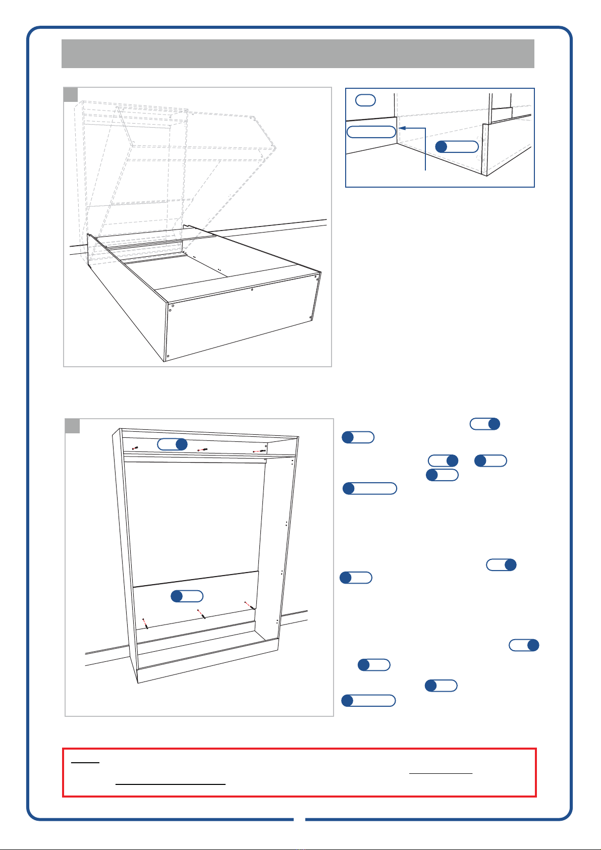
STAGE 2 - FIXING WALL BED CABINET TO WALL
Lay cabinet face down with bottom facing the wall. Lift cabinet at top
pushing towards wall, being careful to have sufficient ceiling clearance.
4
Left End
Skirting Board
Cut skirting recess before pushing
cabinet against the wall if required
Wall
9
10
NOTE:
As there is tension in the Wall Bed Mechanism when in the open position, it is very important that the
cabinet is securely fixed to the wall.
(illustrated fixing points may vary due to wall stud locations)
3
back
7
Back
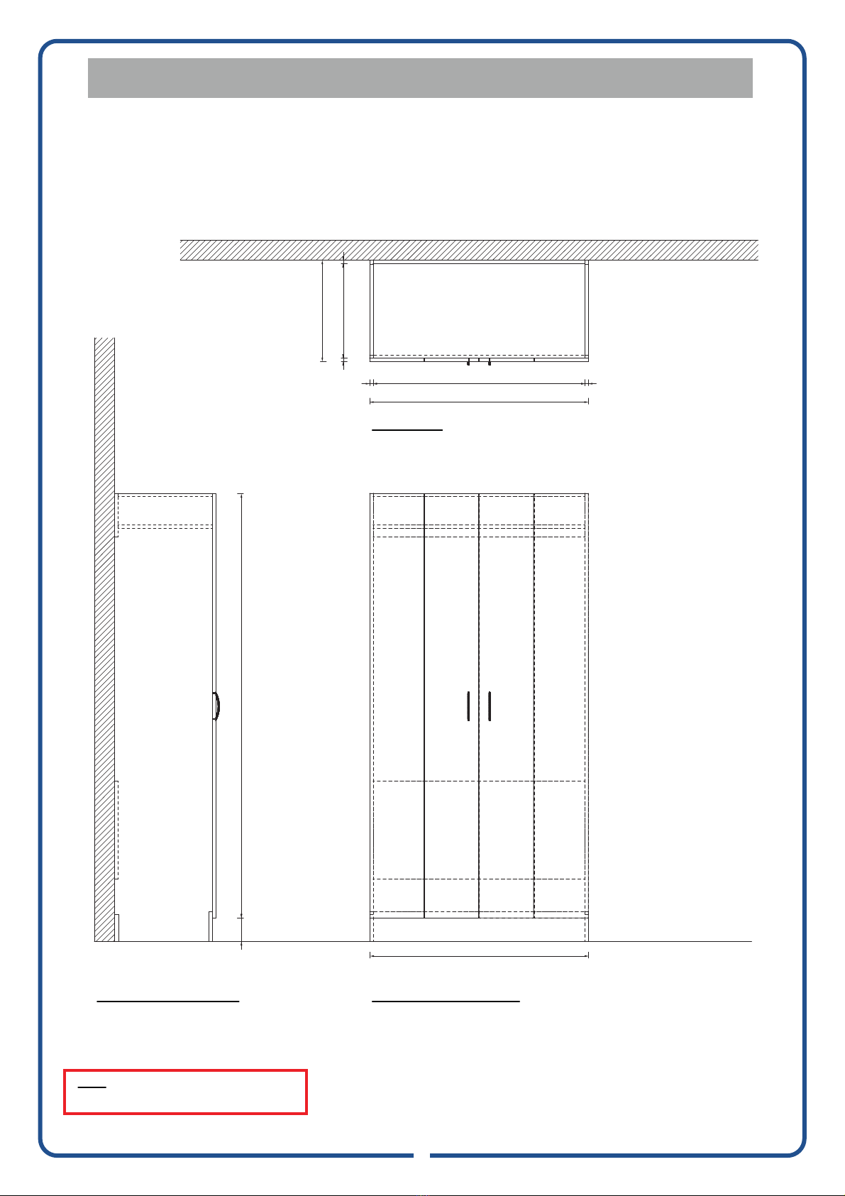
NOTE: To ensure the cabinet sits neatly against the
wall when upright, it may be necessary to cut a
larger recess into the bottom left and right hand end
of cabinet to go over skirting.
Using a spirit level, find the correct vertical and
horizontal position. Mark this position on the wall
with a pencil, if location of install is out of level,
ensure you pack base of cabinet to level cabinet. If
unit is installed in a non level position, doors may not
align correctly.
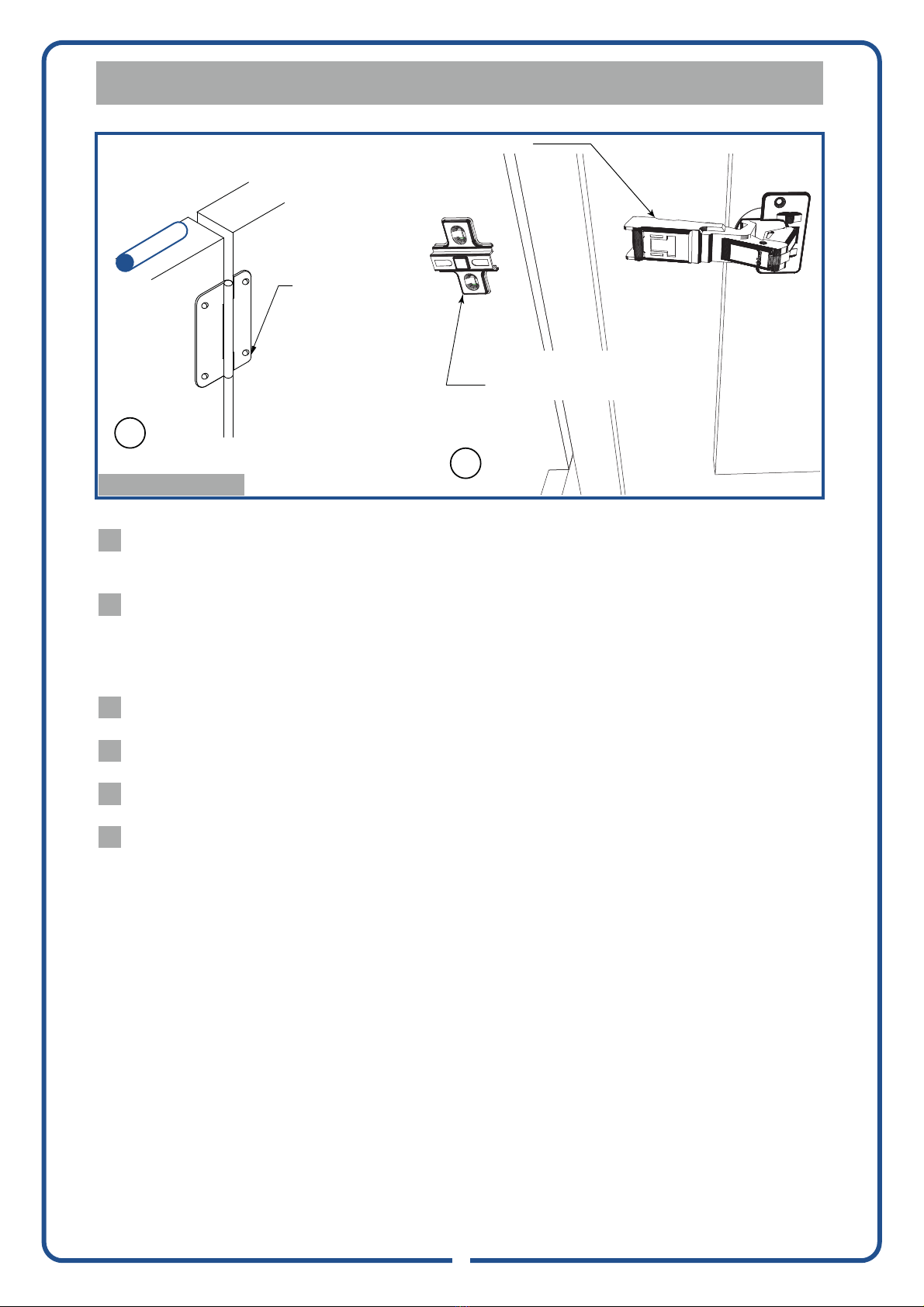
Fastening Option 1 - Gyprock / Fibro / Timber Walls
Locate wall studs and drill holes on and
to to align with wall studs.
Using 65mm screws fix and to wall.
Countersink screws on to avoid damage to
. Put on screw cover caps supplied
over 65mm screw fixings.
Fastening Option 2 - Brick / Masonry Walls
Predrill holes (avoiding mortar joints) on and
and mark locations on wall to suit.
Move cabinet aside.
Using a 6.5mm masonry bit, drill 60mm deep holes into
the wall and insert green wall plugs supplied.
Move cabinet back into place against wall and fix
and to wall using 65mm screws.
Countersink screws on to avoid damage to
. Put on screw cover caps supplied
over 65mm screw fixings.
7
Back
3
Back
7
Back
3
Back
7
Back
14
Pillow Catch
7
Back
14
Pillow Catch
7
Back
3
Back
7
Back
3
Back