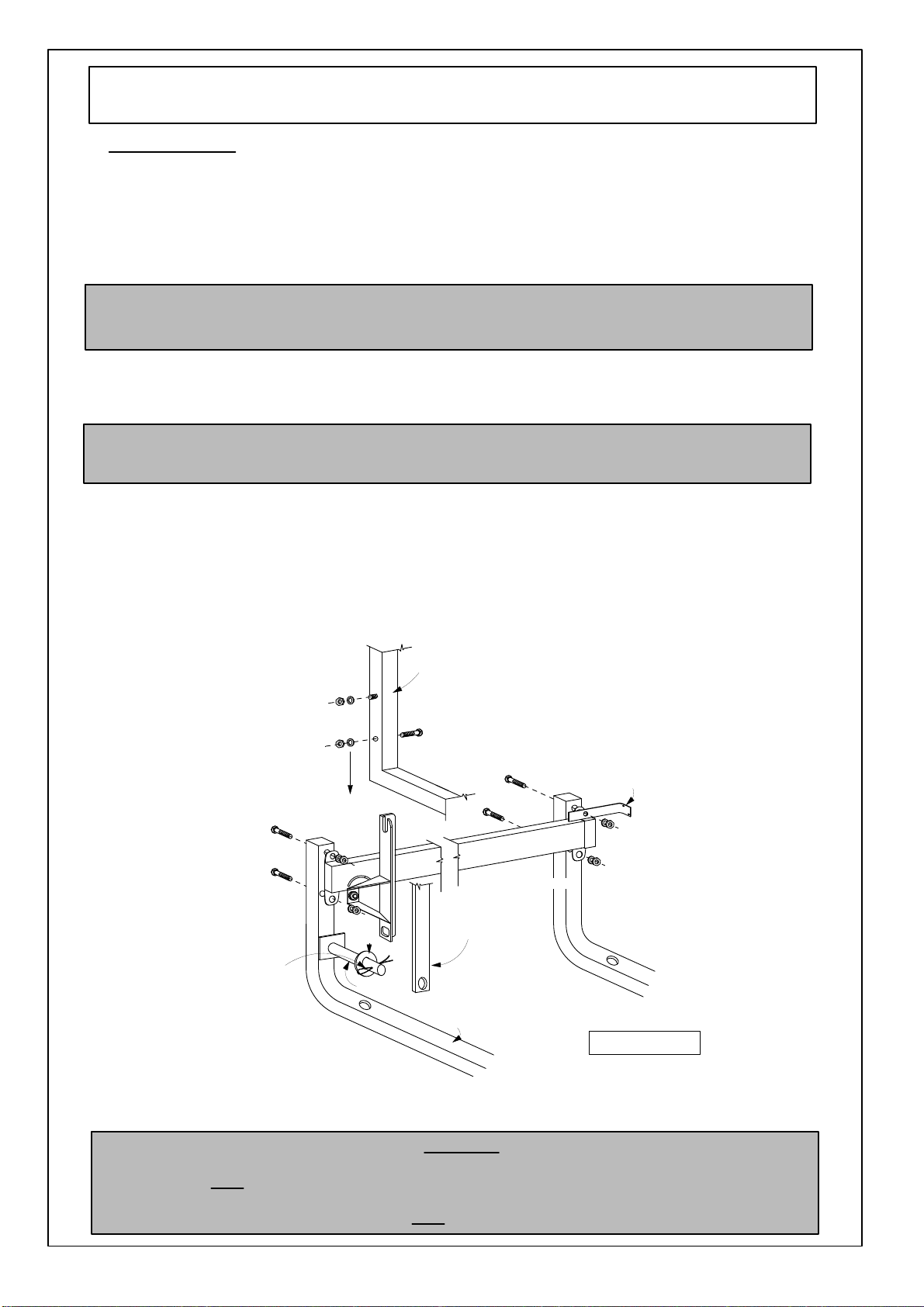
pardo QUEEN User manual

ASSEMBLY
INSTRUCTIONS
QUEEN
Tools
Required For Assembly
DIY
WALL
BED
CABINET & MECHANISM
No
2
&
No
4
Phillips
Head
Screwdrivers
Electric
Drill
(Hammer
Drill
for
Masonry)
Spirit
Level
Hammer
Pliers
Socket
Set
No
2
Slot
Head
Screwdriver
6.5mm
Masonry
Drill
Bit
Adjustable
Spanner
26.02.13

17
deg.
angle
to
both
edges
(refer
to
detail)
340mm
240mm
Board
is
to
lean
back
against
the
wall
Pillowcatch
Head
Board
with
4
x
holes
Bolt
thru
back
of
pillowcatch
so
that
the
nut
is
on
the
inside
of
the
mechanisim
Mechanisim
Piano
Hinge
Cupboard
1.
4.
3.
2.
5.
6.
Panels
(Queen)
1
x
Top
1
x
Top Back Rails
1
x
Left
Hand
End
1
x
Right
Hand
End
1
x
Front
Skirting
1
x
Bottom
Back Rail
4
x
Door
Panels
1
x
Pillow
Catch
1
x
Head
Board
Panel #
1
2
3
4
5
6
7-10
11
12
Size (mm)
1655
x 464
1655
x 250
2227
x 480
2227
x 480
1655
x 150
1655
x
570
2108 x 419
1500
x
370
1500
x
270
9.
10.
8.
7.
1.
11.
12.
Piano
hinge
Both
edges to
be cut
at
17
degrees
Detail
Cabinet
Components
Pillowcatch
DIAGRAM
1

SCREWS
INCLUDED
Chipboard
Screws
*
65mm
Screws
for
attaching
to
wall.
*
60
x
25mm
x
4
gauge
csk
screws
for
interfold
hinges
26
x
Cam Bolts
10
x
Green Wall
Plugs
26
x
Cams
2
x
Handles
6
x
Interfold
Hinge
2.
10
x
Mounting
Plates
10
x
Clip on
Hinge
refer
to
detail
1
2
3
4
5
6
8
7
Mechanism
Components
Hardware
1.
AUTOMATIC
FOOT
2.
BED
FRAME
3.
CONNECTING
ROD
4.
SPRING
MECHANISMS
5.
WALL
MOUNTING
BRACKETS
6.
CRADLES
7.
MATTRESS
GUARD
8.
EXTENSION
ARM
DIAGRAM
1

Right
hand
end
Left
hand
end
Floor
Front
Skirting
Bottom
back
rail
Top
back
rail
Top
1.
2.
4.
3.
6. 5.
Step
1
-
Cabinet
Assembly
NOTE:
STEP
1.
IS
ONLY
REQUIRED
IF PURCHASING CABINET
WITH
BED
MECHANISM
*
Place right hand
end
#4 on
top
of
panels
#1, #2,
#5
and
#6
ensuring
all
wooden
dowel
and
cam
bolts
are
inserted
correctly.
Tighten
all
cams.
Refer
to
Diagram 3
*
Lay
left
hand
end #4
on
floor
with
cam
bolts
upright.
*
Join
shelf
#2
to
left
hand
end
#4
and
tighten
cams.
*
Join
top
#1
to
left
hand
end
#4
and
tighten
cams.
*
Join
top
back
rail
#3
to
left
hand
end
#4,
top
#1
and
shelf
#2.
Tighten
cams.
*
Join
bottom
back
rail
#7
to
left
hand
end
#4
and
tighten
cams.
*
Join
front
skirting
#6
to
left
hand
and
#4
and
tighten
cams
Refer to
Diagram
2
*
Using
hammer,
tap
cams
into
20mm
holes
in
all
panels
where
required.
*
Screw
cam
bolts
into
5mm
holes
in
all
panels
where
required.
Hammer
fix
cam
in
place.
Screw
fix
cam
bolt into
5mm
holes.
3.
DIAGRAM
2
DIAGRAM
3

Skirting
Board
Wall
Cut
skirting recess
before
pushing cabinet
against
the
wall
End
Panel
Front
Panel
DETAIL
B
Fastening
with
angle
brackets
DETAIL
A
Wall
plugs
Refer
to
detail
B
Refer
to
detail
A
Step
2
-
Fixing
Cabinet
To
Wall
*
Lay
cabinet
face
down
with
bottom
facing
the
wall.
*
To
ensure
the
cabinet
sits
neatly
against
the
wall
when
upright,
it
may
be
necessary
to
cut
a
larger
recess
into
bottom
of
left
and
right
hand
end
of
cabinet
to
go
over
skirting.
(refer
to
detail
B)
*
Lift
cabinet
at
top,
pushing
towards
wall,
being
careful
to
have
sufficient
ceiling
clearance.
*
Place
cabinet
into
position
against
the
wall
and,
using
a
spirit
level
against
either
the
right
or
left
hand
end
and
the
top,
find
the
correct
vertical
and
horizontal
position.
Mark
this
position
on
the
wall
with
a
pencil.
PLEASE NOTE
As
there
is
a
lot
of
tension
in
the
Wallbed
when
in
the open
position,
it
is
very
important
that
the
cabinet
is
securely fixed
to
the wall.
IMPORTANT
NOTE:
Before
moving
cabinet
upright,
ensure
all
cams
are
tightened
securely.
*
Locate
wall
studs
and
mark
clearly
with
pencil.
*
Sit
angle
brackets
in
cabinet
top,
flush
with
top
and
back
edge
and
against
the
wall
studs.
Ensure
that
the
twin
hole
side
of
bracket
is
against
the
wall.
*
Fix
angle
brackets
through
wall
into
studs using
65mm
screws
provided.
*
Ensure
cabinet
is
in
correct
vertical
position.
Fix
bottom
of
brackets
into
cabinet
top
using
16mm
screws.
FASTENING
OPTIONS
1
USING
ANGLE
BRACKETS
(for
gyprock,
fibro
or timber
walls)
FASTENING
OPTIONS
2
*
Ensure
cabinet
is
in
correct
vertical
position.
*
With
a
pencil
or
nail,
mark
the
wall
through
the
predrilled
holes
in
the
top
back
rail
and
the
bottom
back
rail.
*
Move
cabinet
back
into
place
against
wall.
*
Fix
top
back
rail
to
wall
using
61mm
screws.
Put
on
cover
caps.
(for
brick/masonry
walls)
*
Move
cabinet
aside.
Using
a
6.5mm
masonry
bit,
drill
60mm
deep
holes
into
wall
and
insert
wall
plugs
supplied.
*
Fix
bottom
back
rail
to
wall.
Countersink
screws
to
avoid
pillow
catch
scraping
on
them.
*
Fix
bottom
back
rail
to
wall.
Countersink
screws
to
avoid
pillow
catch
scraping
on
them.
4.

Split
pin Extension(#8)
Cradle(#6)
Connecting rod(#3)
Spring
Mechanism(#4)
Bed
frame(#2)
Washer
Wall
mounted
bracket(#5)
Step
3
-
DIY
Mechanism
Assembly
/
Instructions
*
Attach spring mechanisms (#4) to front
and
back cradle
(#6)
using
small
nuts
and
bolts
provided.
Ensure to attach
the
wall
mounted
brackets
(#5) with
the
ends
turned
inwards
together
with
the spring
mechanism
to
the
top
rear
bolt.
(See
diagram
4)
*
Fix
the cradle assembly to the
floor
using
the 75mm screws
provided.
50mm green wall plugs are also provided if
fixing
to
concrete
floor.
*
Once
the
cradle
is
fixed
to
the
floor,
fix
the
wall
mounted
brackets
(#5)
to
the
wall
using
the
28mm
screws
provided.
50mm
green wall plugs are also provided if
fixing
to concrete
or
brick walls.
*
Lower
the
bed
frame
in
between
the
mechanism
arms
and
bolt
through
the
predrilled
holes
to
the
cradle
assembly.
You
might
find
that
the
bed
frame
will
be
a
tight
fit
in
between
the
mechanism
arms.
(See
diagram
4)
*
Remove
the
split
pin
and
washer
from
the
extension
(#8)
and
attach
the
connecting
rod
(#3)
to
the
extension
through
the
predrilled
hole
on
the
connecting
rod
(#3)
and
replace
the
washer
and
then
the
spit
pin.
You
might
need
to
lower
the
bed
frame
slightly
to
line
up
the
extension
(#8)
and
the
connecting
rod
(#3).
.
(See
diagram
4)
*
Attach
the
red
handle
supplied
to
the
Automatic
foot
(#1)
using
the
screws
provided.
To
avoid
damage
to
the
connecting
rod,
be
sure
that
the
bed
is
lowered
using
the
red
handle.
NOTE:
If
fixing
through
a
carpet
floor,
it
is recommended
that
a small
cut
be
made in
the
surrounding
area
to
be
drilled
so
that
no threads are pulled in
the
carpet
pile. Also
if
fixing
to
a timber floor, 2mm
pilot
holt
is
to
be
drilled
in the floor before
screwing
through
the
cradle
into
the
floor.
NOTE:
It
is
very important
that
the
cradle
is
fixed
back
to
the wall
and
floor securely
as
there
will
be
substantial
tension
exerted on
the
cradle when
the
mechanism
is
in
the
lowered
position.
WARNING
When
operating
the
wall
bed
mechanism
the
bed
frame
must
be
carefully
lowered
all
the
way
to
the
floor
and
NOT
left
to
drop
freely.
If
the
bed
frame
is
lowered
without
the
weight
of
a
mattress
it
may
spring
back
causing
injury.
Do
not
try
to
vary
the
tension
of
the
spring
mechanism
as
it
is
NOT
adjustable.
DIAGRAM 4
Refer
to Diagram
4
*
If
not
using
pillow
catch,
bolt
on
mattress
guard(s)
to
the
top
of
the
bed
frame
through
the
predrilled
holes
and
using
nuts
and
bolts
provided.
5.

(i)
Ensure
Butt
of
hinge
is
on
inside
of
doors
Inside
Face
A
(ii)
Attaching
Clip-on
Hinges
Door
Cabinet
(iii) Drawing showing
Door
adjustment
by screw on mounting plate
5b
Step
4
-
Mounting
Bi-Fold
Doors
*
Attach
interfold
hinges
to
door
panel
edges
to
form
two
sets
of
bi-fold
doors.
*
Insert
clip-on
hinges
into
hinge
holes
on
outside
edges
of
door
panels.
Fix
hinges
to
doors
using
screws
provided.
*
Attach
doors
to
cabinet
by
clipping
hinges
onto
mounting
plates
on
cabinet
end
panels.
*
Adjust
doors
if
necessary
by
screw
adjustment
where
hinge
meets
hinge plate.
Note:
Ensure
that
butt
of
hinge
is
on
inside
of
doors
*
Attach
handles
to
doors.
6.
DIAGRAM
5

Plan
n.t.s
Side
Elevation
n.t.s
2227
mm
Wall
464
117 2108
150
2
7.
Carcase
Construction
DIAGRAM
11
1655mm
Queen
505
Min
464mm
For
250mm
thick
mattress
NOTE:
ALL
BASED
ON
16mm
BOARD
CONSTRUCTION
16
Other pardo Indoor Furnishing manuals
Popular Indoor Furnishing manuals by other brands

Freedom
Freedom 23741171 manual

Homak
Homak GS00765021 Owner's and operator's manual

Canvas
Canvas ELENA 063-8950-0 Assembly instructions

Noble House Home Furnishings
Noble House Home Furnishings Loveseat Assembly instructions

Next
Next STOCKHOLM TL SHELF Assembly instructions

Rauch
Rauch 82496.8440 Assembly instructions

Furniture of America
Furniture of America CM4641E Assembly instructions

Furniture of America
Furniture of America CM2677-CE Assembly instructions

Renz
Renz C 07 Assembly instruction

Amart Furniture
Amart Furniture KORI 58235 Assembly instruction

Bouclair
Bouclair 9389932 Assembly instructions

Showcases Direct
Showcases Direct DL400 Assembly instructions