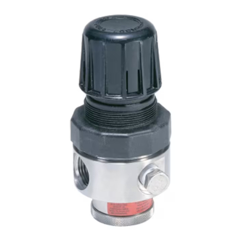
Parker Pneumatic BSP Series Operating manual

Bulletin 407659 Part No 494689
Installation & Setting
Instructions
Rev. 0 Page 1/8
Date 13.03.1999
P3P-R Pressure Regulator
BSP Series : P3P – RP11C100G
P3P – RP11C106D
P3P – RP11C107D
P3P – RP11C400G
P3P – RP11C406D
P3P – RP12T100G
P3P – RP12T106D
P3P – RP12T107D
P3P – RP12T400G
P3P – RP12T406D
P3P – RJ12C100G
P3P – RJ12C106D
P3P – RJ12C107D
P3P – RJ12C400G
P3P – RJ12C406D
P3P – RJ14C100G
P3P – RJ14C106D
P3P – RJ14C107D
P3P – RJ14C400G
P3P – RJ14C406D
NPT Series : P3P – RP91C100G
P3P – RP91C106D
P3P – RP91C107D
P3P – RP91C400G
P3P – RP91C406D
P3P – RP92T100G
P3P – RP92T106D
P3P – RP92T107D
P3P – RP92T400G
P3P – RP92T406D
P3P – RJ92C100G
P3P – RJ92C106D
P3P – RJ92C107D
P3P – RJ92C400G
P3P – RJ92C406D
P3P – RJ94C100G
P3P – RJ94C106D
P3P – RJ94C107D
P3P – RJ94C400G
P3P – RJ94C406D

494689 P3P-R Pressure Regulator
2
CONNECTION DIAGRAMS
P3P-R…..0G P3P-R…..6D
-
Control signal 0...10V or 4...20mA
Supply voltage 24V
Gnd
Gnd
CTRL
24V
+
-
+
1
5
2
4
6
+
+
-
-Output 0 ...10V
Control signal 0...10V or 4...20mA
Supply voltage 24V
Output 4...20mA
P3P-R…..7D
1
5
2
4
6
+
+
-
-
Output 0 ...10V
Control signal 0...10V
Supply voltage 24V
Output alarm 0/24V
1 . POTENTIOMETER P1 2 . POTENTIOMETER P2
Set up of calibration Set up of zero offset
P max
(10 bar)
P min.
0.2 bar
min. 0.1V
min. 4.3 mA max. 10 V
max. 20 mA
Control
signal
min. 1 bar/10V
max.5 V/10 bar
P max
(10 bar)
P min.
0.2 bar
min. 0.1V
min. 4.3 mA max. 10 V
max. 20 mA
Control
signal
3 bar
3V
8.8 mA
Pmax
(7 bar)
P min.
0.2 bar
min. 0.1V
min. 4.3 mA max. 10 V
max. 20 mA
Control
signal
min. 1 bar/10V
max.3.5 V/7 bar
Pmax
(7 bar)
P min.
0.2 bar
min. 0.1V
min. 4.3 mA max. 10 V
max. 20 mA
Control
signal
3 bar
3V
8.8 mA
max.
min.
Min., max., calibration
Standard factory set up
Zero shifting, min., max.
Rotation of potentiometers
Remark : All special calibrations, even the analog output signal calibration, have to be askedand made by the factory.
P3P-R…C….
P3P-R…T…

494689 P3P-R Pressure Regulator
3
POSITION OF POTENTIOMETERS
P3P-R…..0G
P1
P2P3P4
P5
24V
GND
GND
CTRL
T1/T HOLD
IN
HYST OFFS CAL
P3P-R…..6D P3P-R…..7D
IN
24V
CTRL
GND
GND
OUTU
OUTIA P1
P2P3P4
P5
T1/T HOLD HYST OFFS CAL
IN
24V
CTRL
GND
GND
OUTU
OUTIA P1
P2P3P4
P5
T1/T HOLD HYST OFFS CAL
P8
P6
P7
P9
P6
P7
BASE PRINTED BOARD ASSEMBLY
OUTPUT SIGNAL MODULE

494689 P3P-R Pressure Regulator
4
PORT CONNECTIONS RECOMMENDED MOUNTING POSITION
Upright, electronic on the top
PA
R
Inlet pressure max. 12 bar.
Inlet pressure must be
at least 1 bar higher
than regulated pressure.
Outlet port
Regulated pressure.
Exhaust
ELECTRICAL CONNECTIONS SPARE PARTS KITS
P1
P2P3P4
P5
24V
GND
GND
CTRL
T1/T HOLD
IN
HYST OFFS CAL
24V
GND
GND
CTRL
12
3
45
6
6P +
POWER SUPPLY
27.6
20.4
24
V
DC – Supply 24 V ±15 %
In case of rectified voltage supply (from AC to DC)
The residual ripple should be smaller than 1 V.
a
1.4..1.8 Nm
3.5..4 Nm
1.. 1.2 Nm
TORQUES
P3P-R…..00G
P3P-R….06D
P3P-R….07D
b
Max. 1V

494689 P3P-R Pressure Regulator
5
INSTALLATION AND ELECTRICAL
CONNECTIONS
INSTALLATION
Before connecting the regulator P3P-R,
pay attention to the following instructions:
- Connect the regulator as close as
possible to the apparatus which will be
regulated (resulting in higher precision and
shorter response times);
- Piping section of pressure supply should
be sufficiently large;
- Connect the air filter (25-50µ, Dew point 2
°C) upstream from the regulator, and a
lubrificator if necessary, downstream;
- It is recommended to mount the regulator
in a vertical position, electronic on top.
With a flat mounting plate or an angle
mounting plate (accessories), connect the
regulator to the pneumatic network.
Connect the pressure supply on the inlet
port P and the regulation circuit with the
outlet port A.
It is recommended to use a silencer in the
exhaust R of types P3P-RJ…...
ELECTRICAL CONNECTIONS
The P3P-R program offers two connection
possibilities:
- by means of a cable gland Pg 13.5 and
screw terminals on the printed circuit plate;
- by means of a DIN circular plug-in
connector with crimp contacts.
A wire section of 0.75 mm2 is
recommended for the 24 V = power supply,
a shielded cable for the control signal.
Power supply
Direct current 24V ±15%
(details see page 4).
Electrical connection diagrams
See page 2.
Ensure that both "supply" and "control"
groundings are not interconnected outside
the P3P-R as they are already connected
internally.
Wire colours
Pole ➀= BK (black, supply voltage - )
Pole ➁= YE (yellow, output signal
I/alarm+)
Pole ➂= RD (red, supply voltage + )
Pole ➃= BN (brown, output signal U + )
Pole ➄=WH (white, control signal - )
Pole ➅= BU (blue, control signal + )
1.0. Pg 13.5 CABLE GLAND
CONNECTION
- To access the screw terminals, first
remove the plastic cover by unscrewing
both cross-head tapping screws.
- Pass the cable through the cable gland
Pg 13.5.
-Connect the wires on the screw
terminals according to the electrical
diagram.
-Put on the cover and fasten it with the
tapping screws. Screw in the first turn
of the thread by hand, thenwith a
screw-driver screw down with a torque
of 1 Nm.
- Position the cable and fasten it by the
cable gland screw.
- Set up the inlet pressure
(max. 12 bar).
1.1. Serie P3P-R…….G
Supply voltage 24 V-DC:
Pole ( - ) on terminal Gnd
Pole ( + ) on terminal 24 V
Control signal U or l:
Pole ( - ) on terminal Gnd
Pole ( + ) on terminal CTRL
2.0. CIRCULAR PLUG-IN CONNECTION
(for series P3P-R…….D)
- The electrical connection of the pressure
regulator is obtained by a 6-pole circular
plug-in connector with crimp contacts.
- It is not necessary to remove the cover.
The P3P-R is equipped with a mounted
plug-in connector.
- The contact positions are marked with (1)
to (6) on the pin socket (6 poles +
grounding).
- Crimp the pin-contacts and insert them in
the pin socket according to the electrical
diagrams.
- Position the cable, fasten it by the cable
gland and mount the plug on the regulator.
- Set up the inlet pressure (max.12 bar).
2.1. Serie P3P-R……6D
with output module
(0-10Vand4-20mA)
Supply voltage 24 V-DC:
Pole ( - ) pin ➀
Pole(+)pin➂
Control signal U or l:
Pole (-) pin ➄
Pole (+) pin ➅
Sensor output signal 0 - 10 V:
Pole ( - ) pin ➄
Pole(+)pin➃
Sensor output signal 4 - 20 mA:
Pole (-) pin ➄
Pole (+) pin ➁
2.2. Serie P3P-R……7D
with output module
(0 - 10 V and alarm 0/24 V)
Supply voltage 24 V-DC:
Pole ( - ) pin ➀
Pole (+) pin ➂
Control signal U or l:
Pole ( - ) pin ➄
Pole (+) pin ➅
Sensor output signal 0 - 10 V:
Pole ( - ) pin ➄
Pole (+) pin ➃
Alarm output signal 0/24 V-DC:
Pole (-) pin ➄
Pole (+) pin ➁
Recommended load resistances
Sensor output signal 0-10 V:
10 kΩmin.
Sens. output signal 4-20 mA:
500 Ωmax.
Alarm output signal 0/24 V: 1.2 kΩmin.
P3P-R SETTING INSTRUCTIONS
The P3P-R regulators are fully adjusted
and quality controlled at the factory to
obtain standard specifications.
Control signal:
0to10Voltor4to20mAcorrespondingto
an output pressure range of 0.2 to 10 bar
(1 V resp. 5.6 mA corresponds
to 1 bar).
Hysteresis:
~ 100 mbar. This value is adjusted in order
to obtain an inaudible correction of the two
2-way solenoid pilots when there is no
change of the control signal.
Setting corrections:
In case where the original calibration would
not fully correspond to the required setting
(e.g.: variation due to the temperature), a
correction may be made by the user. To
access the base circuit plate and its
potentiometers, first remove the plastic
cover.
Base printed board assembly:
P1 = Calibration of control signal
0-10V/4-20mA
P2 = Zero pressure offset
P3 = Hysteresis
Setting up all other sealed potentiometers
is strictly forbidden. Any action on the
sealed potentiometers would be subject to
a loss of warranty. Parker Pneumatic
reserves all rights to modify the position of
the potentiometers on the electronic
packages.
Output signal module:
P6 = 0utput signal 0 - 10 V
(correction of amplitude)
P7=0ffsetcorrection0-10V
P8 = 0ffset shifting correction
for4-20mA
P9 = Alarm setting up 0/24 V
The setting of the output signal module is
only possible within certain limits.
Attention: Take care to set up only the
indicated potentiometers on page 3,
according to instructions. For carrying out
the set up, it is necessary to have a
Voltage and/or Current Multimeter as well
as a precision manometer or a pressure
sensor with digital display. The P3P-R.
should be pressurized and energized
except when setting up the alarm.

494689 P3P-R Pressure Regulator
6
MAINTENANCE
The P3P-R does not need any maintenance. However the
quality of used air should be checked periodically. For
revision use spare parts kits as follows:
Kit P3P-R Type Order N°
a*
P3P-RJ..C….
P3P-RP..C….. 481203-193
P3P-RP..T….. 481203-215
b* P3P-J..C…. 481203-194
Before carrying out the replacement of spare parts with the help of
Kits "b", please contact the factory for agreement. It needs Know
How and special test apparatus. Furthermore the warranty
conditions should be re-defined.
See page 4
SET UP METHOD
Modifications of setting up are permitted only for:
- hysteresis;
- alarm level.
However if a correction of the calibration or a zero offset
correction cannot be avoided, proceed first to the calibration
set up and then to the pressure offset. Position of set up
potentiometers on the printed circuit plates are as shown on
page 3.
All P3P-R base circuit plates are equipped with the same
potentiometers. The following instructions are therefore valid
for the ranges P3P-R..00G, 06D and 07D.
To access the base circuit plate, first remove the plastic
cover by unscrewing off both cross-head screws. For the
series with integrated output module - types P3P-R..06D and
07D -first pull out the upper outlet signal plate from its guide
slot. The base electronic package is now accessible.
Do not displace this printed board assembly during the set up
of the potentiometers. The factory set up of the hysteresis
corresponds to approx. 100 mbar. After carrying out the set
up, reset the output module in the guide slots and screw on
the plastic cover.
Forced exhaust
The P3P-R regulator is equipped with an electronic safety
circuit which automatically drops the output pressure at 0 bar
when the control signal is below 130 mV ±30 mV or 4.26 mA
±0.06 mA. Therefore no setting up should be done when the
control signal is below the above-mentioned value. Any
modification of zero pressure offset should be done
accordingly.
Time lag relay
To neutralize the alarm output signal during the control signal
changes, the use of a synchronized time lag relay is
necessary. The duration of the time lag has to be defined by
the customer in function of each pneumatic installation.
Attention: Itiscompulsorytosetthecontrolsignalat0Vor
4 mA each time an installation is turned off (during the night
or the weekend) if the inlet pressure is equally shut down.
When the installation cannot be fully exhausted, it is
necessary to assure that the deviation between the control
value and the inlet pressure remains smaller than 1 bar.
It is recommended to reset the control signal at 0 V or 4 mA
respectively before re-connecting the supply voltage
(24 VDC).
BASIC CIRCUIT
Start
Apply the maximum control signal
correct pressure? If yes
If no
Adjust P1
Apply a control signal = 0
Apply a control signal = 1 V or 4.5 mA
Correct pressure? If no
If yes Adjust P2
End
This loop should be repeated as many times as necessary (average 5 to 6
times)
NEVER TOUCH P4 AND P5
OPTIONS
Start 0-10 V voltage output
Apply the maximum control signal
Is the output voltage correct? If yes)
If no
Adjust P6 (calibration
Apply a control signal = 0
Apply a control signal = 1 V or 4.5 mA
Is the output voltage correct ?
If yes If no
Adjust P7 (offset)
Alarm output option 4-20 mA output option
Discharge the inlet pressure and vent the circuit
in which the P3P-R is installed
Apply a control signal corresponding to
the required alarm level
Adjust P9 to check the alarm signal activation
Reduce the control signal level and slowly increase it again
to check the alarm activation at the required level
Correct ? No
Yes
End
Apply a control signal = 0 V or 4 mA
Adjust P8 (offset of 4-20 mA) to get a corresponding
output current of 4 mA.
End

494689 P3P-R Pressure Regulator
7

494689 P3P-R Pressure Regulator
Parker Hannifin plc Parker Pneumatic Division
Pneumatic Division Richland, Michigan, USA
Walkmill Lane, Bridgtown Phone: (616) 629 5000
Cannock, Staffs, WS11 3LR Fax: (616) 629 5385
Tel: 01543 456000
Fax: 01543 456001
This manual suits for next models
42
Table of contents
Other Parker Pneumatic Controllers manuals