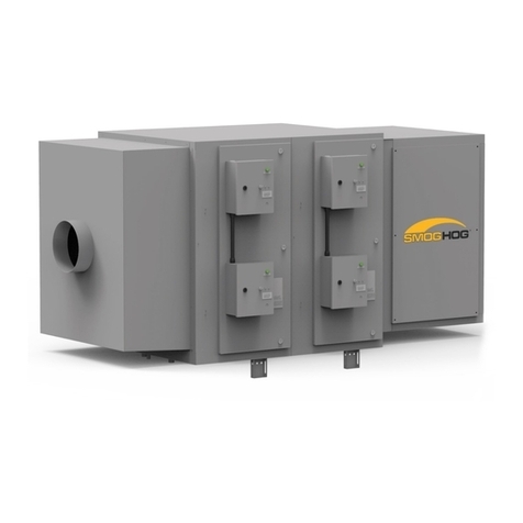
Parker CRYSTAL-AIRE User manual

Modular Air Cleaning
Systems
Owner’s Manual

2
Introduction
These instructions must be thoroughly read and understood before installing and
operating this product. Failure to operate this product in accordance with the instructions
set forth in this manual can lead to unsafe operating conditions and may void warranty.
For additional information, refer to this manual or contact the factory for recommenda-
tions. Please have the dryer serial number and model ready when contacting the factory.
KNOW YOUR EQUIPMENT
READ AND SAVE THESE INSTRUCTIONS
Your CRYSTAL-AIRE®UV should provide many years of trouble-free service. This
manual will help you understand the operation of your unit. It will also help you understand
how to maintain it in order to achieve top performance. For quick future reference, fill in
the system information in the spaces below. Should you need assistance, call the Parker
Customer Service number shown below. To expedite your service, have the following
information available when contacting Parker.
Unit Model #: __________________________________________________________________
Unit Serial #:___________________________________________________________________
System Accessories:
______________________________________________________________________________
______________________________________________________________________________
______________________________________________________________________________
Installation Date: _______________________________________________________________

3
i
Page
Safety Precautions ...................................................................................................4
Introduction .............................................................................................................6
Application ...............................................................................................................6
Air Changes Per Hour (Ach).....................................................................................7
Specifications ..........................................................................................................7
Installing Your CRYSTAL-AIRE®uv System ....................................................... 8-9
Application .........................................................................................................8
Inspection...........................................................................................................8
Unpacking ..........................................................................................................8
Specification.......................................................................................................8
Installation ..........................................................................................................8
Wall Mount .........................................................................................................9
Ceiling Mount .....................................................................................................9
Electrical Requirements.....................................................................................9
How Your CRYSTAL-AIRE®uv System Operates ................................................10
Blower Module .................................................................................................10
Fan On / Off Switch .........................................................................................10
Fan Speed Selector .........................................................................................10
Uvc Lamp .........................................................................................................10
Media Filters.....................................................................................................10
Odor Filter ........................................................................................................10
Filter Status Light.............................................................................................10
Cleaning .................................................................................................................11
Blower Module ................................................................................................11
Lamp Breakage / Disposal .............................................................................11
Uvc Lamp ........................................................................................................11
Maintenance & Service .........................................................................................12
Blower Module .................................................................................................12
UVC Lamp ........................................................................................................12
Filter Elements .................................................................................................13
Replacement Parts .......................................................................................... 14-15
Troubleshooting Guide .........................................................................................16
Wiring Diagrams ................................................................................................... 17

4
IMPORTANT SAFETY INSTRUCTIONS
To reduce the risk of fire, electric shock, or injury when using your air cleaner, follow these basic precautions:
Avoid exposure to direct or reflected germicidal ultraviolet rays. Germicidal ultraviolet
rays are harmful to the eyes and skin.
SAFETY PRECAUTIONS
We have provided many important safety messages in this manual and on
your SFC dust collector. Always read and obey all safety messages.
• Disconnect power before servicing.
• Use two or more people to unpack, move and install the
air cleaning system.
• The air cleaner must be properly grounded. Ensure power
supply and power receptacle have appropriate grounding.
• Replace all access panels before operating.
• Wear protective clothing and safety glasses when handling
collection components or servicing the air cleaner
• Permanent wired electrical connections should only be
made by qualified personnel and be in accordance with
local and national codes and regulations.
• Do not operate UV without complete lamp enclosure in
place, or if glass lens is broken.
• Do not override safety interlock.
• Do not mount under any source of moisture or condensa-
tion, such as humidifiers, cooling coils, etc.
• Do not operate without access cover secured.
• Stay clear of blowers, or other moving parts that can
cause injuries
• Do not use in explosive atmospheres.
• Do not use with combustible dusts
• Use nonflammable cleaners.
• Do not collect emissions which are explosive.
• Keep flammable materials and vapors, such as gasoline,
away from air cleaner.
• The unit should be inspected frequently for correct fan
operation, UV lamp operation and filter element condition.
• The CRYSTAL-AIRE®uv system should not be used for
support of personnel or material.
• Operate only in a safe and serviceable condition.
• Intended for indoor use only.
• Do not alter design or construction.
• Keep inlet and outlet openings clean and clear of debris.
!
!WARNING
This is the safety alert symbol.
This symbol alerts you to potential hazards that can kill or hurt you and others. All safety messages will follow the safety alert
symbol and the word “DANGER” “WARNING” or “CAUTION”. These words mean:
Indicates a hazardous situation which, if not avoided, will result in death or serious injury.
Indicates a potentially hazardous situation which, if not avoided, could result in death or
serious injury.
Indicates a potentially hazardous situation which, if not avoided, may result in minor or
moderate injury.
CAUTION used without the safety alert symbol indicates a potentially hazardous situation
which, if not avoided, may result in property damage.
!DANGER
!WARNING
!CAUTION
CAUTION

5
PARKER INDUSTRIAL GAS FILTRATION
AND GENERATION DIVISION
COMBUSTIBLE DUST HAZARDS –
SMOGHOG AND DUSTHOG POLLUTION
CONTROL SYSTEMS
Pursuant to National Fire Protection Agency (NFPA) Standards,
the owner/user is required to test their dust mixtures to
evaluate and understand potential combustion or deflagration
hazards that may exist. In addition, NFPA standards require
the owner/user to perform and have record of a Dust Hazard
Analysis (DHA) if there is potentially a combustible material
involved within or exposed to the process.
The DHA serves as a systematic review of the process to:
1) Identify where fires and explosions can occur;
2) Identify the potential causes and consequences, and;
3) Determine if existing and proposed safeguards are suf-
ficient.
It is the responsibility of the owner/user to evaluate, interpret
and document any associated risk in their process including
adherence and compliance to any and all applicable local,
state and federal codes, standards, laws and regulations.
It is the sole responsibility of the equipment owner/user of
record to coordinate and perform sample material collection
and combustion/explosivity testing of any and all dust and
material that will be extracted and filtered by the Air Pollution
Control (APC) filtration equipment and to notify Parker of the
results prior to any discussion involving equipment specifica-
tion and solution recommendation. It is recommended to utilize
a Certified Industrial Hygienist (CIH) or certified safety expert
that is properly trained, licensed and approved and to use a
licensed and approved dust testing facility for proper dust and
material analysis, testing protocol and reporting procedures.
A sample of testing facilities and list of Industrial Hygiene (CIH)
and other occupational and environmental health and safety
(OEHS) consultants can be located through AIHA (American
Industrial Hygiene Association) website.
To minimize the risk of fire or explosion, user must ensure
proper installation, operation and maintenance of Parker
equipment. Since application, installation, operation and
maintenance are beyond the control of Parker, Parker
disclaims any liability or responsibility for damage from fires
or explosions regardless of origin. Parker recommends that
all APC dust collection equipment, installation and
application conform to any and all applicable local, state and
federal standards, codes, laws and regulations including the
addition of appropriate fire or explosion protection systems
including but not limited to venting, mitigation, suppres-
sion and isolation when and where required. Installation of
Parker equipment should be by a licensed contractor that is
also experienced in potential fire and explosion hazards and
adheres to related local, state and federal codes, standards,
laws and regulations. Parker is not an expert nor certi-
fied design consultant in relation to spark, fire or explosion
mitigation including but not limited to detection, mitigation,
suppression and isolation pf combustible dusts and materi-
als. Therefore, Parker recommends that any industrial air
filtration system recommendation, design or solution be
reviewed, approved, stamped and signed by an industry
expert consultant in air filtration systems, combustible dust/
materials or certified safety expert such as a Certified Industrial
Hygienist (CIH) or a Certified Professional Engineer (PE) who is
a licensed and certified expert with industrial filtration system
design and application including adherence and compliance
to any and all applicable local, state and federal codes,
standards, laws and regulations.
Pursuant to Parker’s Offer of Sale (terms and conditions) and
by accepting the purchased equipment, Buyer and owner/
user agree to defend, indemnify, and hold harmless Parker, its
successors, assignees, suppliers, shareholders, directors,
officers, employees, agents, and affiliated companies from
all losses, costs, damages, demands, claims, liabilities, fines,
penalties or any other expenses (including attorneys’ fees,
court costs, and expert fees) (collectively “losses”), caused
or contributed to in any way by Buyer or owner/user’s failure
to follow these instructions and/or failure to properly install,
apply, operate, or maintain the equipment purchased from or
supplied by Parker, or losses caused or contributed to in
any way by Buyer’s and owner/user’s failure to provide
accurate information, specifications or dust explosivity values.
6
INTRODUCTION
READ THIS MANUAL FIRST
This manual contains important safety information. If you
do not fully understand the instructions, consult your local
CRYSTAL-AIRE®uv distributor or PARKER sales representa-
tive before proceeding with installation or operation of the
CRYSTAL-AIRE®uv system.
YOUR NEW AIR CLEANER
Your new air cleaner is a germicidal UVC high efficiency air
filtration and disinfection system that operates separately to an
existing heating ventilating and air conditioning (HVAC) system.
With the combination of UVC and high efficiency media filtra-
tion technology, it is the most advanced product of its type on
the market today and will provide you with a safer, healthier
environment. As you begin its operation, we would like you to
know some important facts.
Your CRYSTAL-AIRE®uv system is designed to draw con-
taminated air from a room, pass it through the cleaning unit,
then exhaust cleaned air back into the room. When correctly
applied, the CRYSTAL-AIRE®uv may help address improving
air filtration and enhancing air cleaning.
Your CRYSTAL-AIRE®uv system can also be configured as a
negative room air pressure machine where it can draw con-
taminated air from a room, passing it through the cleaning
unit, and exhausting outside may help address the ASHRAE
Standard 170: Ventilation of Health Care Facilities.
We have manufactured an air cleaner engineered to rigid
specifications and quality control checks. A warranty backs
every air cleaner that leaves our factory.
Like any piece of equipment, your air cleaner needs periodic
maintenance. Properly cared for, it will operate at peak effi-
ciency for many years.
APPLICATION
For best results and to assure maximum air quality, your
CRYSTAL-AIRE®uv system should be started before the air
becomes contaminated and should operate continuously or on
a timed interval to provide for constant air purification.
Your CRYSTAL-AIRE®uv system has been thoroughly tested
prior to shipment from the factory.
NOTICE: Your CRYSTAL-AIRE®uv system has been
designed for commercial applications with a high con-
centration and turnover of people such as offices, fast
food and dine-in restaurants, bars and nightclubs, medical
facilities including exam rooms, residence halls, training
and workout areas, reception and wait areas, cafeterias
and food prep areas, restrooms, classrooms, break rooms,
conference and meeting rooms. If you have any questions
regarding the application contact your local CRYSTAL-
AIRE®uv distributor or PARKER sales representative.
NEGATIVE PRESSURE ROOM AIR
APPLICATION
Your CRYSTAL-AIRE®uv system can also be configured as a
negative air machine where the room in which it is installed will
remove extracted air that passed through the filtration and UV
chamber from the room thus creating and maintaining a nega-
tive pressure situation or vacuum within the room helping limit
recirculation and spread of airborne particulate and contami-
nants within the room or surrounding areas. This configura-
tion may help address ASHRAE Standard 170: Ventilation of
Health Care Facilities
The CRYSTAL-AIRE®uv can be fitted with a duct flange on the
outlet of the unit. Flexible or rigid duct can be connected to
the outlet flange and routed to the outdoors. This allows the
unit to be configured to help address the ASHRAE Standard
170: Ventilation of Health Care Facilities. This will allow the unit
to be used to maintain a negative air pressure within the room
or space where the unit is installed, and the air is exhausted
out of the room.
ROOM AIR RECIRCULATION
Your CRYSTAL-AIRE®uv system is designed to draw contami-
nated air from a room, pass it through the cleaning unit, then
exhaust cleaned air back into the room. This exhaust air in
turn, moves contaminated air around the room, and back to
the inlet of the unit. Air Changes per hour (ACH) or directions
for air patterns and for proper application and placement of the
CRYSTAL-AIRE®uv system should be established by your local
CRYSTAL- AIRE®uv distributor or by PARKER sales represen-
tative. When correctly applied, the CRYSTAL-AIRE®uv may
help meet the ASHRAE reopening of schools and universities
guidance and recommendations.
There are recommendations from ASHRAE on ACH such as 2
ACH for classrooms and other levels for different and varying
spaces, please reference ASHRAE for ACH recommendations.
The ACH will be determined by the application and factored in
based on the final installation type and definition.
AIR CHANGES PER HOUR (ACH)
An example is a standard educational classroom. The ASHRAE;
Reopening of Schools and Universities guidance recommends
that a ventilation rate to of five to six (5-6) ACH.
EXAMPLE: If a classroom dimensions are 25’ wide by 30’
long and a ceiling height of 10’, that would calculate to 7,500
cubic feet. In order to achieve 6 ACH, the air handling device
would require 750 cfm. The CRYSTAL-AIRE®uv unit runs at a
maximum of 800 CFM, therefore the application would require
(1) CRYSTAL-AIRE®uv unit to meet the ASHRAE; Reopening of
Schools and Universities recommended ACH.
(See Chart 1) ON NEXT PAGE.

7
CHART 1
ACHCFM CHART for ROOM SIZES and AIR CHANGES PER HOUR (ACH)
# ACH
150 ft2
10x15
300 ft2
15x20
400 ft2
20x20
500 ft2
20x25
600 ft2
20x30
750 ft2
25x30
1200 ft2
30x40
3 75 150 200 250 300 375 600
6 150 300 400 500 600 750 1200
9 225 450 600 750 900 1125 1800
12 300 600 800 1000 1200 1500 2400
SPECIFICATIONS
INPUT POWER: 115V/1P/60HZ
OPERATING CURRENT, Amps: 12
INPUT POWER CORD LENGTH, ft.: 8
INPUT POWER CORD PLUG: NEMA 5-15
MAXIMUM AIRFLOW, cfm: 800
NOISE RATING, dB(A): 50-65 dBA
PREFILTER EFFICIENCY: MERV 8
19 3/16
48 1/4
19 15/16
PREFILTER FILTER AREA, sq.ft.: 4.8
MAIN FILTER EFFICIENCY: 99.97% True-HEPA
MAIN FILTER FILTER AREA, sq.ft.: 113
UV LAMP LIFE ESTIMATE, hours: 17,000
CABINET DIMENSIONS, (LxWxH), inch: 19 x 20 x 48
UNIT WEIGHT: 158 pounds
SHIPPING WEIGHT 200 pounds

8
INSTALLING YOUR
CRYSTAL-AIRE®uv
CLEANING SYSTEM
Inspection
Upon receipt of your unit, check for any shipping damage.
A damaged carton indicates that the equipment may have
received rough handling during shipping that may have caused
possible internal damage. Notify your delivery carrier immedi-
ately and enter a claim if any damage is found.
Unpacking
When unpacking the unit, always inspect the CRYSTAL-
AIRE®uv components for damage. Before operating unit
remove all packing material such as cardboard and any pack-
aging material that protects the unit during shipment.
UNIT MAY TIP WHEN REMOVING FROM PALLET
UNIT IS HEAVY. USE CAUTION WHEN REMOVING
FROM PALLET
DO NOT DROP UNIT FROM PALLET TO FLOOR
AS DAMAGE TO UNIT MAY OCCUR
Installation
The CRYSTAL-AIRE®uv product is available where it can be
located or installed in (4) variations including;
1) Mobile/floor mount,
2) Wall mount using included wall bracket for ambient
3) Ceiling mount above ceiling panels and connected
to ducting (ducting not included).
4) Hanging mount for ambient
Mobile/Floor Mounting:
Open the access panel to expose the pre-filter, UV lamp and
main filter. Inspect these elements to ensure they are properly
installed and correctly positioned and locked into place.
Use assistance when lifting. Cabinet must always be
supported from beneath until the unit has been secured.
The CRYSTAL-AIRE®uv should not be used for support
of personnel or material.
CRYSTAL-AIRE®uv systems may be installed by suspension
from ceiling joists or other overhead supports. Threaded rod or
eyebolts and chain may be used to hang the unit.
FALL HAZARD
Check the CRYSTAL-AIRE®uv unit weight on page 7 before
installing and ensure the supporting or suspension steel work
has sufficient load bearing capacity.
Wall Mounting:
1. Remove the wall bracket from CRYSTAL-AIRE®uv
2. Locate an appropriate area on the wall to mount the
CRYSTAL-AIRE®uv.
a. To allow for adequate flow, allow a minimum of 3 feet
empty space from the inlet or outlet of the CRYSTAL-
AIRE®uv
b. Wall or mounting location must be able to support
CRYSTAL-AIRE®uv (refer to weight specifications).
c. Recommend a minimum 3/8” X 2½” lag screw a mini-
mum of (4) places into a wooden stud or other
solid object.
3. There are (10) mounting holes in the wall mount bracket.
a. Use a minimum of (4) mounting holes across the top
cross bar when attaching the wall mount bracket to
the structure.
b. Equally space the fasteners for optimal support.
c. Level and fasten the wall mount bracket with fasteners
of sufficient length, strength, and type to support the
CRYSTAL-AIRE®uv (refer to weight specifications).
4. Remove the front cover from the unit for access to the
(4) 9/16” diameter mounting holes located along the top
edges of the unit.
5. Carefully lift and align the CRYSTAL-AIRE®uv into position
using a material lift or other supporting device.
a. USE CAUTION WHEN LIFTING, UTILIZE LIFTING
DEVICES AS NEEDED TO SUPPORT CRYSTAL-
AIRE®uv WEIGHT!
6. Fasten the CRYSTAL-AIRE®uv to the mounting bracket
using the (4) ½” bolts, lock washers and nuts provided.
a. Torque the bolts to 57 ft lbs.
7. Once the CRYSTAL-AIRE®uv is mounted, replace
the front cover
8. Plug in the power cord to appropriate power supply.
9. The CRYSTAL-AIRE®uv is now ready for operation
CAUTION
!DANGER
!DANGER
LIFTING HAZARD

9
Hanging and Ceiling Mounting:
Check location to ensure there is sufficient clearance above the
ceiling and for proper filter access door removal and to connect
inlet and outlet ducting for ceiling mounted models. For hang-
ing models, allow for 3 feet unobstructed path to the inlet and
outlet of the unit.
A 26-inch minimum clearance is required above the ceiling and
3 feet is required in front of the modules to replace filters and
service the CRYSTAL-AIRE®uv.
1. To install, carefully raise the CRYSTAL-AIRE®uv to the
mounting location.
a. USE CAUTION WHEN LIFTING, UTILIZE LIFTING
DEVICES AS NEEDED TO SUPPORT CRYSTAL-
AIRE®uv WEIGHT.
2. After the CRYSTAL-AIRE®uv is in place, secure with ½”
threaded rod, chain or cable from each corner of cabinet
using the mounting holes.
a. If using cable or chain, ½” eyebolts (not supplied) can
be attached to the CRYSTAL-AIRE®uv
i. If using cable, ensure cable is rated to support
CRYSTAL-AIRE®uv weight (refer to weight specifi-
cations).
ii. Structure that CRYSTAL-AIRE®uv is suspended
from must be able to support the product weight.
b. If using threaded rod, nuts should be used on both the
inside and outside of the cabinet to lock the threaded
support in place
3. Once the CRYSTAL-AIRE®uv is mounted, replace the front
cover
4. Plug in the power cord to appropriate power supply.
a. The CRYSTAL-AIRE®uv is now ready for operation
Note:
If the optional carbon filter was purchased, install it in the
appropriate slot located between the blower unit and the out-
let grille (see figure for location). Reinstall the access panel.
Plug the unit into appropriate power supply and press the unit
power switch to the on position.
Turning the unit on:
The switch will illuminate as the fan begins to create airflow
and the UV lamp will illuminate. It is typical that there is a
slight fan delay on start-up and when changing speeds.
CRYSTAL-AIRE®uv ELECTRICAL
CONNECTION
CRYSTAL-AIRE®uv system modules are provided with a power
cord with NEMA 5-15 plug. Any power source that the
CRSYTAL-AIREuv®unit is applied to must have the appropriate
power requirements as indicated in the specification section
to properly function and be protected by an NEC (National
Electric Code) approved fuse or circuit breaker. The motor on
the motor/blower module has built-in thermal protection.
Wiring diagrams are located in the back of this manual.
8
16
24
32
9/16 TYPICAL
16
16
16
16
FIGURE 1 (All dimensions are inches)

10
FILTRATION / UV FUNCTION
In any CRYSTAL-AIRE®uv system, contaminated air is drawn
through a 4 stage filtration chamber, cleaned and conditioned,
then exhausted by the system blower. Airborne particles, both
large and very small, are trapped in the process in a selected
combination of multiple filtration stages. Cleaned air then exits
the system blower and is directed back to the occupied space
or outdoors, depending on the duct design. Figure 2 shows
how the CRYSTAL-AIRE®uv units process contaminated air.
There are inlet and outlet grids to protect from large particles or
items entering into the unit and only allow for air flow.
The first filtration stage is the pre-filter stage which uses a
MERV 8 glass-fiber filter to remove large particles. This pro-
tects downstream items including the UV lamp configuration.
The air then enters a small UV irradiance chamber to help neu-
tralize particulates as they pass through this zone. The air then
collides with and is filtered by the 99.97% True-HEPA filter to
separate and contain particles that are as small as 0.3 microns.
As the particles are contained on the surface or embedded in
the pre-filter or True-HEPA filer media, the constant illumina-
tion and application of UV energy exposed to these medias
attacks and deactivates viral, bacterial, and fungal organisms.
An optional final filter can be installed after blower section to
help with odors and smells as the air is returned into the space.
PREFILTER
This is a one-inch-thick disposable MERV 8 filter consist-
ing of pleated, glass fiber media inside a metal frame. The
filter traps large particles before they can enter the primary
filter stage. The prefilter evenly distributes air across the
primary filter, maximizing efficiency and extending filter life.
UV LAMP
The UV Ultraviolet germicidal lamp operates at 254nm
wavelength spectrum. It features four high intensity UV-C
lamps to sterilize the air of bioaerosols. The UV-C uses
ultraviolet light to deactivate viruses, bacteria and spores
MAIN FILTER
A disposable 99.97% at 0.3 micron True-HEPA box filter is
used where extremely high efficiency or special duty is required.
HEPA is a small-pore media filter. Since True-HEPA filters require
special sealing against by-pass, a gasket installed on the HEPA
frame and a clamp to provide filer frame to base frame con-
nection is in place to provide special sealing against by-pass.
ODOR FILTER
Activated Carbon: This disposable filter option follows the
motor/blower section and is designed to remove odorous con-
taminants. This 1” thick filter retains odors by adsorbing gas-
eous materials from the airstream. It removes odorous material
by trapping it in tiny pores in its carbon media. Cabinet and
media frame configuration are shown in page 15.
FIGURE 2

11
POWER SWITCH
The power on/off switch is located on the outside of the
CRYSTAL-AIRE®uv as part of the control panel area. This is a
two-position rocker switch that is used to power the unit. When
the switch is illuminated and in the ON position, the fan will begin
to run, and the UV lamps illuminate. It is typical that there is a
fan delay on startup and when changing fan speeds. Airflow
should be present at the exhaust of the unit and the UV illumi-
nation window at the base of the unit will be glowing UV light.
FAN SPEED SELECTOR
The fan speed selector has four positions, each position repre-
sents a factory set airflow. Speed 1 is the lowest airflow volume
at 300 CFM where speed 4 is the highest airflow volume at 800
CFM. Speed 2 is set to 400 CFM and speed 3 is set to 600 CFM.
CHANGE FILTER INDICATOR
An internal factory set mechanical differential pressure switch
attached to a red indicator lamp on front control panel is
to indicate when the pre-filter or main filter is clogged and
requires replacement. When the change filter red indicator
lamp illuminates, it is recommended that the prefilter and / or
HEPA filter be replaced to provide optimal airflow and efficiency.
INTERLOCK SWITCH
The electrical interlock switch prevents power to the blower
and UV lamp when the access door or the pre-filter is not
in place. Do not defeat its operation as injury and harm may
result. Voltage is still present in the control section if the unit
is still plugged into the power source. DISCONNECT UNIT
FROM INPUT POWER BEFORE SERVICING.
Refer to FILTER CHANGEOUT section on page 13

12
MAINTENANCE AND SERVICE
This section is for the use of trained service personnel only.
Disconnect from Power Source
Before Servicing
UV LIGHT SOURCE
Risk of exposure to ultraviolet radiation. Eye damage
may result from directly viewing the light from UV lamps.
NOTE: Handle UV lamps with clean oil free hands
or gloves.
Risk of exposure to excessive ultraviolet radiation. Do
not operate UV without complete lamp enclosure in
place or if glass viewing lens is broken. Eye damage
may result from directly viewing the light produced by
these lamps. To reduce the risk of exposure to UV radia-
tion, take UV protection measures for personnel during
servicing.
The following procedures will expose hazardous live
and moving parts.
Switch Off/isolate the electrical supply to the
CRYSTAL-AIRE®uv system.
Due to the simplicity of the design, breakdowns are
restricted to these components:
• motor/blower
• UV lamp and ballast power supply
• fan control switch
• fan speed selector
• low voltage transformer
MOTOR/BLOWER MODULE
MOVING PARTS
Motors are maintenance free. No lubrication is required.
RISK OF ELECTRIC SHOCK. UV LIGHT SOURCE.
UV LIGHT SOURCE
Risk of exposure to ultraviolet radiation. Eye damage
may result from directly viewing the light from UV lamps.
UV LAMP BREAKAGE
CAUTION: Broken Quartz is SHARP.
Wear PPE including Tyvek suit, protective gloves, respirator
(N95 or better) and eye protection when handling broken ultra-
violet lamp(s). In the event of breakage, DO NOT use a house-
hold vacuum cleaner to pick up quartz fragments. Sweep up
debris into a sealable plastic bag then place into another seal-
able plastic bag. Dispose of broken fragments and any items in
contact with the glass fragments and quartz properly.
DISPOSAL OF UV LAMPS
Germicidal UVC lamps, like standard fluorescent lamps contain
small amounts of mercury. UV lamps should not be placed
in the trash. Dispose of properly. Follow local, state and
federal guidelines, standards and regulations for proper lamp
disposal. A list of commercial lamp recyclers can be found
through the National Electrical Manufacturers Association
www.lamprecycle.org website.
!DANGER
!CAUTION
!CAUTION
!DANGER

13
FILTERS
The pre-filter, main filter and carbon filter will require periodic
replacement. Refer to filter changeout section below, however
actual pre-filter and main filter replacement interval may vary
depending on the quality of the air that which is being filtered.
For dirty and dusty environments, the pre and main filter will
require more frequent replacements whereas a cleaner envi-
ronment will require less frequent pre and main filter replace-
ments. The carbon filter should be replaced as indicated.
It is recommended that appropriate Personal Protection
Equipment (PPE) is used when changing the filters including
but not limited to a respirator, face shield, gloves and protec-
tive clothing. Any filter that is being disposed of should be
immediately removed and placed in an approved containment
bag and disposed of following installation site guidelines for
hazardous waste.
FILTER CHANGEOUT
• Replace pre-filter every 3 months or when change filter
light is illuminated
• Replace main filter every 36 months or when change filter
light is illuminated
• Replace carbon filter monthly – The carbon odor filter is not
monitored by the change filter indicator light
If the red filter indicator light on the remote switch plate is
illuminated when the system is operating, the filter(s) require
changing. To replace filters:
1. Disconnect power.
2. Remove access panel
3. Remove the prefilter and discard per local, state
and federal disposal guidelines.
4. Install a proper replacement.
5 Reinstall access panel
6. Restart the unit. If the light remains on, go to the next step.
7. Remove the main filter and discard per local, state and
federal disposal guidelines.
8. Install a proper replacement.
9. Restart the unit. If the light remains on, refer to the
Troubleshooting Guide. ON PAGE 16
NOTE:

14
PART DESCRIPTION PART NUMBER REFERENCE
Mobile Unit 01-10258-00
Wall Unit 01-10258-01
Ceiling Unit 01-10258-02
Hanging Unit 01-10258-03
Pre-lter DPHT-101
Main Filter MERV 13 2809349
Main Filter MERV 14 2909237
Main Filter HEPA 2971351
Power Switch EX0040-1
Fan Speed Selector Switch 20-2755
Indicator Lamp 20-1064
Door Interlock Switch 20-2907
Transformer 20-1062
Differential Pressure Switch 20-1063
Fan Motor 22-10052
Caster GC0007
UV Lamp 20-1066
UV Lamp Ballast 20-1067
Odor Filter 33-10163
Sight Glass (Not Shown) 40-1040A1
Fan Speed Selector Switch Knob 39-10082
Fure-8A SLOBLO 25-10014
PARTS ORDERING

15
PARTS ORDERING
Prelter
Main Filter HEPA,
Optional MERV 13/14
Door Interlock Switch
Differential Pressure
Switch
Speed Selector
Switch
Transformer
UV Lamp
Caster
Fan Speed Selector Switch
Fan Speed Selector
Switch Knob
Power Switch
Indicator Lamp
Odor Filter
UV Lamp Ballast
Fan Motor
Fuse

16
PROBLEM POSSIBLE CAUSE CORRECTIVE ACTION*
A. Fan Switch on, not
illuminated, blower and UV
operates.
1. Defective switch. 1. Replace switch
B. Control switch on,
indicator light and UV on, blower
does not operate.
1. Foreign object blocking motor.
2. Faulty fan switch or faulty
motor speed switch
3. Connector not properly
connected (at control switch).
4. Improperly wired
5. Motor faulty.
6. Door not fully secured
1. Check impeller spins freely
2. Replace fan on/off or motor speed
switch.
3. Check connection at fan on/off or speed
switch.
4. Check wiring
5. Replace motor.
6. Fully tighten door screws
C. Fan Switch on, not illuminated,
blower not operating, UV off.
1. Loss of input supply voltage.
2. Control switch defective.
3. Filter access door not installed or seated.
4. Pre-lter may not be installed correctly.
5. Check lter access door and pre-ler
inter lock switches.
1. Trace circuit for cause of voltage loss.
2. Replace control switch
3. Check the lter access door is in place
and activating the door interlock switch.
4. Check that the pre-lter is installed and
activating the lter interlock switch.
5. Check that the interlock switches are
operating correctly, consult a qualied
electrician.
D. Poor air quality. 1. Media lters are loaded.
2. Main lter is not locked into place and
there is air bypass.
3. Unit operating at low speed.
4. Unit or grill location not generating a
good air pattern.
1. Replace lters (refer to Filter Changeout,
page 13).
2. Check that main lter is sealed against
main frame rail and that clamps are
compressing the seal between the lter
and the unit frame rail.
3. Increase blower speed. (Refer to Fan
Speed Selector, page 11).
4. Contact your local distributor or Parker
E. Fan on/off switch is on and
illuminated, fan is operating, UV
lamps are not illuminated.
1. Faulty lamps
2. Lamp ballast not receiving power
3. Defective lamp ballast
1. Replace lamps
2. Check that the lamp ballast is receiving
appropriate voltage.
3. Replace lamp ballast
TROUBLESHOOTING GUIDE
*Refer to wiring diagram and illustrated parts lists.

17
CRYSTAL-AIRE®uv SYSTEM WIRING DIAGRAM

18
Subject to the terms and conditions hereof, Parker-Hannifin Corporation (PARKER) warrants that major structural com-
ponents on MCB, PNP, SDC, SFC, and SHM series will be free from defects in materials and workmanship for ten (10)
years from the date of shipment from Parker. Subject to the terms and conditions hereof, warrants to the original Buyer
of any Parker product (PRODUCT) installed and used as recommended by PARKER in normal service, that if the PROD-
UCT fails or is materially defective within twenty-four (24) months from date of installation or thirty (30) months from the
date of shipment (whichever is earlier), of such PRODUCT, then PARKER, at PARKER’S sole option, will replace the
PRODUCT with the same or equivalent PRODUCT, repair the PRODUCT or refund the original purchase price for the
PRODUCT. Such replacement, repair of payment by PARKER shall be in complete satisfaction of any and all liability of
PARKER and its agents with respect to such PRODUCT. Excluded from any Parker warranty are hose, electrical motors
or consumable products such as flexible hose, belts, filter cartridges, filter media, ESP cells, electrical components,
gasketing, or any component defined by PARKER as a consumable item.
Parker IGFG’s warranty policy covers defects that are due to manufacturing quality. Equipment must be installed,
commissioned and maintained in accordance with Parker IGFG recommendations as documented in the specific user
manual related to your dust or wet collector product. This warranty does not cover defects due to poor environmental
conditions, improper installation, or wear and tear items. This warranty shall be void in case of:
a) Any buyer’s modifications not explicitly approved by Parker IGFG Division,
b) Misuse or failure in maintenance - not in accordance with Parker’s product recommendations,
c) Use of unauthorized or non-genuine Parker replacement parts,
d) Damage caused by corrosion, abrasion, abnormal use or misuse, misapplication, or normal wear and tear,
e) Equipment not properly installed, operated and maintained under normal conditions and recommended applications.
As Buyers exclusive remedy for any defects in the equipment, Parker will exchange or repair any defective parts during
the warranty period, provided such parts are returned, prepaid, to Parker factory. The obligation of Parker is limited to
furnishing replacement parts F.O.B. Parker factory or making repairs at Parker factory of any parts that are determined,
upon inspection by Parker, to be defective. In no event will Parker be responsible for labor or transportation charges for
the removal, reshipment or reinstallation of the parts. Replacement parts will be provided via INCOTERMS EXW from
Parker’s Lancaster NY location. Parker makes no warranty as to goods manufactured or supplied by others.
THE FOREGOING IS THE ONLY WARRANTY, GUARANTEE OR REPRESENTATION OF ANY KIND MADE WITH RE-
SPECT TO THE SUBJECT PARKER PRODUCTS. NO IMPLIED WARRANTY, INCLUDING ANY IMPLIED WARRANTY
OF NONINFRINGEMENT, DESIGN, MERCHANTABILITY OR FITNESS FOR A PARTICULAR PURPOSE, APPLIES TO
THE PRODUCT, AND NO OTHER EXPRESS WARRANTY OR GUARANTY, EXCEPT AS MENTIONED ABOVE, GIVEN
BY ANY PERSON, FIRM OR CORPORATION WITH RESPECT TO THE PRODUCT SHALL BIND PARKER. PARKER
SHALL NOT BE LIABLE FOR LOSS OF REVENUES OR PROFITS, EXPENSE FOR SUBSTITUTE EQUIPMENT OR
SERVICE, STORAGE CHARGES, OR ANY OTHER SPECIAL, INCIDENTAL OR CONSEQUENTIAL DAMAGES CAUSED
BY THE USE, MISUSE OR INABILITY TO USE THE PRODUCT REGARDLESS OF THE LEGAL THEORY ON WHICH
THE CLAIM IS BASED, AND EVEN IF PARKER HAS BEEN ADVISED OF THE POSSIBILITY OF SUCH DAMAGES. NOR
SHALL RECOVERY OF ANY KIND AGAINST PARKER BE GREATER IN AMOUNT THAN THE PURCHASE PRICE OF
THE PRODUCT SOLD BY PARKER AND CAUSING THE ALLEGED DAMAGE. WITHOUT LIMITING THE FOREGOING,
YOU ASSUME ALL RISK AND LIABILITY FOR LOSS, DAMAGE OR INJURY TO YOU AND YOUR PROPERTY AND
TO OTHERS AND THEIR PROPERTY ARISING OUT OF USE, MISUSE OR INABILITY TO USE THE PRODUCT NOT
CAUSED DIRECTLY BY THE NEGLIGENCE OF PARKER. THIS LIMITED WARRANTY IS GIVEN ONLY WITH RESPECT
TO A PRODUCT PURCHASED FROM PARKER OR AN AUTHORIZED PARKER DISTRIBUTOR.
Parker Industrial Gas Filtration and Generation Division
Product Warranty – SMOG-HOG®and
DUST-HOG®Pollution Control Systems

19

Parker Hannifin Corporation
Industrial Gas Filtration
and Generation Division
4087 Walden Avenue
Lancaster, NY 14086
phone 800 343 4048
www.parker.com/igfg
© 2021 Parker Hannifin Corporation. Product names are trademarks or registered trademarks of their respective companies IOM_PKR_CRYSTALAIREuv_052021
PN: 44-10300-0001
Aerospace Filtration Division
Greensboro, North Carolina
336 668 4444
Bioscience & Water
Filtration Division
Bioscience Filtration
Oxnard, California
877 784 2234
Water Purication
Carson, California
310 608 5600
Engine Mobile
Aftermarket Division
Kearney, Nebraska
308 234 1951
Engine Mobile Original
Equipment Division
Modesto, California
209 521 7860
HVAC Filtration Division
Jeffersonville, Indiana
866 247 4827
Hydraulic & Fuel
Filtration Division
Metamora, Ohio
419 644 4311
Industrial Gas Filtration &
Generation Division
Lancaster, NY
800 343 4048
Industrial Process
Filtration Division
Mineral Wells, Texas
940 325 2575
Bioscience Engineering
Filtration Division EMEA
Birtley, United Kingdom
+44 (0) 191 410 5121
Engine Mobile Filtration
Division EMEA
Dewsbury, United Kingdom
+44 (0) 1924 487 037
Gas Separation &
Filtration Division EMEA
Team Valley, United Kingdom
+44 (0) 191 402 9000
Gas Turbine Filtration Division
Alton, United Kingdom
+44 (0) 1420 541188
Hydraulic & Industrial
Filtration Division EMEA
Arnhem, Netherlands
+31 (0) 26 376 0376
Australia Filtration Division
Castle Hill, Australia
+61 2 9634 7777
China Filtration Division
Shanghai, China
+86 21 2067 2067
India Filtration Division
Chennai, India
+91 22 4391 0700
Korea Filtration Division
Hwaseon City, Korea
+82 31 359 0852
Latin America Filtration Division
Sao Paulo, Brazil
+55 12 4009 3500
Parker Filtration Group
Table of contents
Other Parker Air Cleaner manuals

Parker
Parker SMOKEETER SE-40 User manual

Parker
Parker BAS-2010 User manual

Parker
Parker OIL-X EVOLUTION User manual

Parker
Parker BA-DME012-E User manual

Parker
Parker BAC-4015 User manual

Parker
Parker SMOG-HOG PSG User manual

Parker
Parker Domnick Hunter BA-2010 User manual

Parker
Parker BAS-2015 User manual

Parker
Parker BAS-3015 User manual

Parker
Parker SMOG-HOG MSH-05-H User manual
Popular Air Cleaner manuals by other brands

Guardian
Guardian AC9400 Series Use & care instructions

BREATHIFY
BREATHIFY Air Series user manual

Trotec
Trotec Airozon 5000 operating manual

Bionaire
Bionaire PERMAtech BAP1400 Instruction leaflet

Flanders
Flanders Crank Lock HEPA Filter Housing C-3 Specification sheet

Philips
Philips AC1715 quick start guide