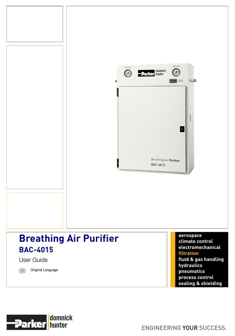
Parker BAC-4015 User manual

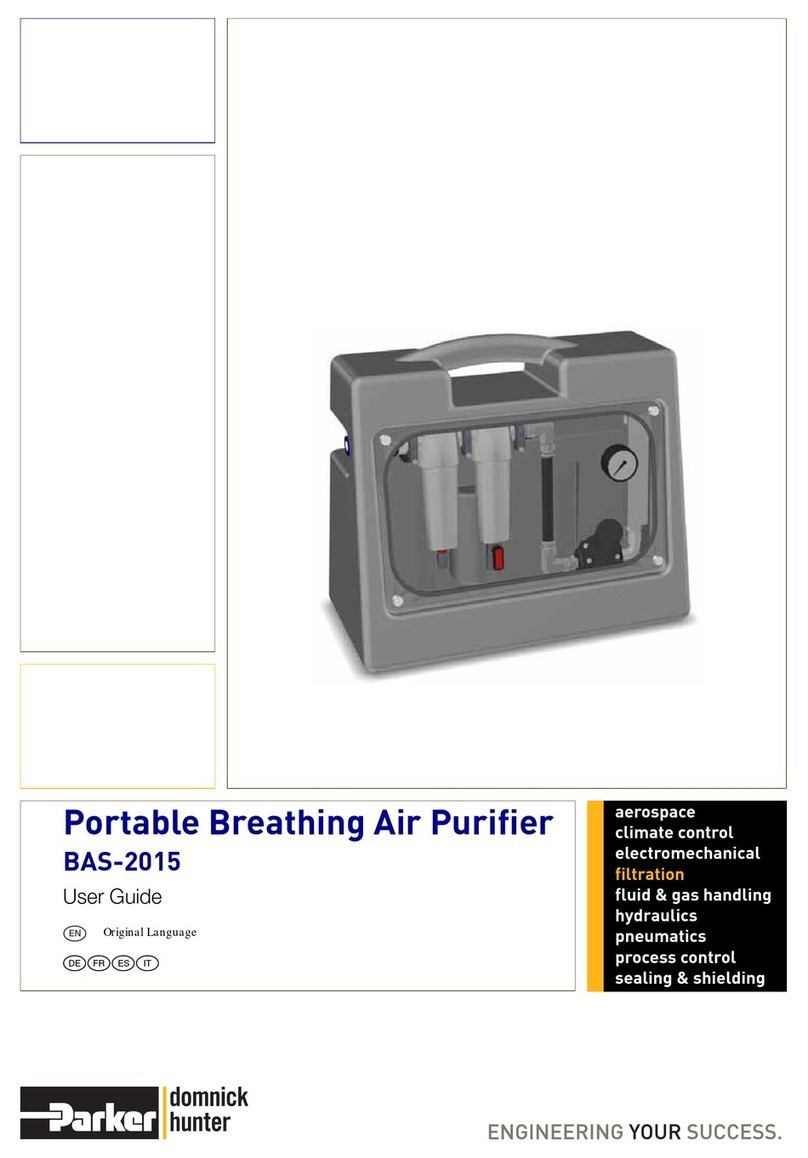
Breathing Air Purifier
BAC-4015
Original Language
User Guide
aerospace
climate control
electromechanical
filtration
fluid & gas handling
hydraulics
pneumatics
process control
sealing & shielding
EN
DE FR ES IT

1
Table of Contents
1 Safety Information ........................................................................................................................................................................................2
2 Description ....................................................................................................................................................................................................3
2.1 Technical Specification........................................................................................................................................................................3
2.2 Weights and Dimensions.....................................................................................................................................................................4
2.3 Receiving and Inspecting the Equipment ..........................................................................................................................................4
2.3.1 Unpacking the Equipment ............................................................................................................................................................4
2.3.2 Lifting and handling ......................................................................................................................................................................4
2.4 Overview of the Equipment .................................................................................................................................................................5
3 Connecting and Operating the Equipment.................................................................................................................................................6
3.1 General Installation Requirements .....................................................................................................................................................6
3.2 Operating the Equipment.....................................................................................................................................................................6
3.3 Safety Features.....................................................................................................................................................................................7
3.3.1 Audible warning of system failure.................................................................................................................................................7
3.3.2 Flow limiting orifice .......................................................................................................................................................................7
3.3.3 Hours run meter ...........................................................................................................................................................................7
4 Preventative Maintenance Kits............................................................................................................................................................8
4.1 Service Intervals ...................................................................................................................................................................................8

2
1 Safety Information
Do not operate this equipment until the safety information and instructions in this user guide have been read and understood by all
personnel concerned.
USER RESPONSIBILITY
FAILURE OR IMPROPER SELECTION OR IMPROPER USE OF THE PRODUCTS DESCRIBED HEREIN OR RELATED ITEMS CAN CAUSE
DEATH, PERSONAL INJURY AND PROPERTY DAMAGE.
This document and other information from Parker Hannifin Corporation, its subsidiaries and authorised distributors provide product or system
options for further investigation by users having technical expertise.
The user, through its own analysis and testing, is solely responsible for making the final selection of the system and components and assuring
that all performance, endurance, maintenance, safety and warning requirements of the application are met. The user must analyse all aspects of
the application, follow applicable industry standards, and follow the information concerning the product in the current product catalogue and in
any other materials provided from Parker or its subsidiaries or authorised distributors.
To the extent that Parker or its subsidiaries or authorised distributors provide component or system options based upon data or specifications
provided by the user, the user is responsible for determining that such data and specifications are suitable and sufficient for all applications and
reasonably foreseeable uses of the components or systems.
This equipment is safe and will not present a risk to health when properly used in accordance with this user guide. It is essential that users
familiarise themselves with its contents and be fully conversant with this equipment and the correct operating procedures before use.
Breathing air equipment is by its very nature used in critical applications. It is therefore essential that only competent personnel trained, qualified,
and approved by Parker Hannifin should perform installation, commissioning, service and repair procedures.
Use of the equipment in a manner not specified within this user guide may result in an unplanned release of pressure, which may cause serious
personal injury or damage.
When handling, installing or operating this equipment, personnel must employ safe engineering practices and observe all related regulations,
health & safety procedures, and legal requirements for safety.
Compressed air must be delivered at a comfortable temperature for breathing.
Ensure that the equipment is depressurised prior to carrying out any maintenance.
Maintenance MUST be carried out regularly to ensure optimum performance. All maintenance, filter element changes and a record of working
hours usage, should be detailed in a maintenance and examination record.
Provision should be made to test the quality of delivered air. Use suitable test equipment, e.g. detection tubes and/or in-line monitoring equipment
and retain the appropriate records.
Parker Hannifin can not anticipate every possible circumstance which may represent a potential hazard. The warnings in this manual cover the
most known potential hazards, but by definition can not be all-inclusive. If the user employs an operating procedure, item of equipment or a
method of working which is not specifically recommended by Parker Hannifin the user must ensure that the equipment will not be damaged or
become hazardous to persons or property.
Should you require an extended warranty, tailored service contracts or training on this equipment, or any other equipment within the Parker
Hannifin range, please contact your local Parker Hannifin office.
Details of your nearest Parker Hannifin sales office can be found at www.parker.com/dhfns
Retain this user guide for future reference.
3
2 Description
The Parker domnick hunter BAC-4015 is a fully portable pneumatically controlled air purification system designed to provide breathing quality
air to a higher level than specified in EN12021 for oil mist, vapour, odour and particulate removal. The BAC-4015 will also remove carbon
monoxide (CO) and reduce carbon dioxide (CO2) to fully meet EN12021 and other international specifications.
The BAC-4015 breathing air purifier utilises 5 separate stages of compressed air treatment, combined together in a compact and robust
housing.
1st Stage - Grade AA - high efficiency coalescing filter for removal of oil/water aerosols and dirt particulate down to 0.01 micrometre, giving a
maximum remaining oil content of 0.01 mg/m3.
2nd Stage - Grade AC - adsorption bed of activated carbon for removal of oil vapours and odours. The downstream air after this stage now has
a maximum remaining oil content of 0.003 mg/m3at a filtration temperature of 21°C.
3rd Stage - Adsorption Purifier regenerative adsorption bed of desiccant for removing water vapour and also reducing the CO2 content prior to
the catalyst stage. The desiccant purifier maintains a low dewpoint by utilising the heatless pressure swing adsorption principle. Cycle time is
controlled by a pneumatic cam timer.
4th Stage - Grade HC - catalytic element for removal of carbon monoxide by oxidation to carbon dioxide through chemisorption and catalysis.
The catalyst is kept active by maintaining a low dewpoint prior to the catalytic bed. This is achieved by the integral adsorption purifier (stage 3).
5th Stage - Grade AA - high efficiency coalescing filter for removal of oil/water aerosols and dirt particulate down to 0.01 micrometre, giving a
maximum remaining oil content of 0.01 mg/m3.
These air purification stages are installed in an epoxy painted steel cabinet with lifting handles and a lockable door. Inlet and outlet pressure
gauges are mounted on the upper facia panel. The outlet pressure can be set as desired using the pressure regulator.
2.1 Technical Specification
BAC-4015
Connections Inlet G 1/2 BSPP female
Outlet G 1/4 BSPP female (x3)
Maximum Inlet Flow Rate 11 L/sec @ 7 bar g (23 scfm @ 102 psi g)
Maximum Outlet Flow Rate 9 L/sec @ 7 bar g (18 scfm @102 psi g)
Maximum Inlet Pressure 10 bar g (145 psi g)
Minimum Inlet Pressure 4 bar g (58 psi g)
Maximum Operating Temperature 30oC (86oF)
Minimum Operating Temperature 1.5oC (35oF)

4
2.2 Weights and Dimensions
2.3 Receiving and Inspecting the Equipment
The equipment is supplied in a sturdy wooden crate designed to be moved using a forklift truck or pallet truck. On delivery of the equipment
check the crate and its contents for damage.
If there are any signs of damage to the crate, or there are any parts missing please inform the delivery company immediately and contact your
local Parker domnick hunter office.
2.3.1 Unpacking the Equipment
The panels of the crate are secured using nails. Starting with the top, carefully remove each panel in turn and store them safely for future use.
2.3.2 Lifting and handling
Lifting handles have been provided on the equipment, however to lift the equipment safely it is suggested that this is to be done by two people.
BAC-4015
H752mm (29.6”)
W515mm (20.3”)
D272mm (10.7”)
(a) 430mm (16.9”)
(b) 394mm (15.5”)
Weight 40Kgs (88.2lbs)
H
(a) (b)
WD

5
2.4 Overview of the Equipment
Ref Description Ref Description
1BAC-4015 Lockable door c/w keys 8G 3/8 Regulator
2Inlet adaptor 9Hours Run Meter
3Outlet manifold 10 Inlet pressure gauge
4AC Grade filter 11 Outlet pressure gauge
5HC Grade filter 12 Audible warning device
6AIR PACK 2000 Dryer 13 Flow limiting orifice
7AA0003G Filter
10 11
1
24
5
8
3
13
12
7
6
9

6
3 Connecting and Operating the Equipment
3.1 General Installation Requirements
Before the BAC-4015 is installed, the piping should be purged with clean dry air to remove any loose debris and/or water from the line.
Downstream piping must be of a type approved and specified for breathing air applications.
Inlet connection to the BAC-4015 is made by a G1/2 BSPP internally threaded pipe connection to IS0228 (BSPP) for use with parallel or taper
fittings. The three outlet connections are G1/4 BSPP internally threaded to IS0228 (BSPP) for use with parallel fittings.
The BAC-4015 must be operated in a vertical position and must not be situated where it is able to tilt or be dislodged from its operating position.
The BAC-4015 has a weatherproof cabinet (NOT WATERPROOF) with a rubber edging strip around the door. During operation, the door must
be in the closed and locked position and should only be opened for maintenance/filter element changes or operation of the pressure regulator
by authorised personnel.
The BAC-4015 must only be used in the direction of flow indicated on the cabinet. No attempt should be made to remove the filters from the
cabinet or loosen any of the retaining bolts which could cause malfunction of the purifier.
Ensure that all connections to the equipment are secure and that compressed air of the correct pressure and flow rate is available to the purifier.
If the line pressure exceeds 10 bar g (145 psi g), install a suitable pressure regulator (not supplied). First ensure that the purifiers outlet pressure
regulator is closed. Carefully open inlet valve or regulator. This action ensures that down stream equipment cannot be subjected to excessive
pressure.
Ensure that the BAC-4015 is securely sited and all air supply lines are safely positioned and not susceptible to damage or constriction.
Air can be supplied from most suitably rated compressors, although care should be taken to ensure that the compressor is operating efficiently
and not overheating. Care should also be taken in the location of the compressor intake to ensure that no harmful contaminants are drawn in.
For heavily contaminated compressed air systems a water separator is recommended which will reduce liquid water and oil.
Under normal circumstances, it is not usual to encounter CO concentrations in excessive levels. If detected then the purifier must not be used.
Provision for air sampling should be made to prove the quality of delivered air using a certified testing agency.
All ancillary equipment such as piping, connections, valves, fittings etc. must be suitable for breathing air purposes, and for the pressure and
flow capacities involved.
3.2 Operating the Equipment
This equipment must be fully checked before every use and any faults MUST be rectified immediately.
To open the BAC-4015 outlet pressure regulator (supplied) and adjust the line pressure, lift locking ring to unlock; turning clockwise to increase
secondary pressure, or anticlockwise to decrease pressure. It is recommended that adjustments are made under flow conditions.
Note: there may be a slight increase in set pressure when flow demand stops until the desired conditions are achieved for the
operators breathing equipment.
Push down locking ring to re-lock. Do not exceed the rated flow - refer to “Technical Specification” on page 3
A limiting orifice is fitted after the outlet pressure regulator to prevent the rated flow from being exceeded.
When the operating condition has been achieved, the breathing air purifier will operate automatically without further adjustments providing that
the inlet supply remains stable within the specified limits.
When air demand is no longer required the inlet valve regulator (not supplied) must be closed and the BAC-4015 isolated from use.
Any disconnection of the purifier must only be made when the system pressure is fully relieved.
Only competent personnel trained, qualified, and approved by Parker domnick hunter should perform installation,
commissioning, service and repair procedures.

7
3.3 Safety Features
The following safety features are incorporated as standard in the BAC-4015 and must not be disconnected, removed, or bypassed in any
manner.
3.3.1 Audible warning of system failure
If the BAC-4015 is depressurised without the operator's knowledge (e.g. compressor failure or system pressure loss), a warning whistle will
sound when the pressure drops to below 4 bar g (58 psi g) (minimum operating pressure).
3.3.2 Flow limiting orifice
This device limits the outlet flow rate proportionally to the line pressure thus ensuring that the volumetric air flow rate of the BAC-4015 is not
exceeded. The flow limiting orifice is located immediately after the outlet pressure regulator.
3.3.3 Hours run meter
The meter gives a visual indication of the operating hours of the BAC-4015.
When pressure to the purifier is established an internal pressure switch closes, operating the meter. The decimal point on the display blinks
when the meter is working. When pressure is removed from the Breathing Air Purifier the meter stops (see ‘Hours Run Meter Schematic’).
The hours run meter is battery operated with an expected 10 year life (not guaranteed). A knock out panel is provided on the facia of the cabinet
to accept the meter. An internal rail is also located behind this panel to house the pressure switch. Air supply to this pressure switch should be
taken from the cam timer motor inlet via a ‘Y’ connector (not supplied).
The fault must be identified and rectified before the equipment is used again.
3
1
2
2 (N)
HOURS RUN METER
PRESSURE SWITCH
TO AIR MONITOR INLET VIA Y-CONECTOR
1 (L)

8
4 Preventative Maintenance Kits
4.1 Service Intervals
Key:
Description of Service Required Service recommended every:
Component Operation
Week
Monthly
3-month
12-month
Complete Assembly Check for air leaks.
Filtration Check the pressure gauges during purging for excessive back
pressure.
Filtration Replace the adsorption filter elements - Activated Carbon (1)
Recommended Service
(1) Unlike oil aerosol removal filters which are changed annually to guarantee compressed air quality, the lifetime of an oil vapour removal filter can be attributed to
various factors and require more frequent changes. Factors affecting the lifetime of adsorption filters are:
Oil vapour concentration - The higher the inlet concentration of oil vapour, the faster the activated carbon capacity will expire.
Bulk oil - Adsorption filters are designed to remove oil vapour and odours, not liquid oil or aerosols. Poorly maintained or non-existent pre-filtration will cause the OVR filter capacity
to quickly expire.
Temperature - Oil vapour content increases exponentially to inlet temperature, reducing element life. Additionally, as temperature increases, the adsorption capacity decreases,
again reducing element life.
Relative Humidity or Dewpoint - Wet air reduces the adsorptive capacity of the carbon.
Compressor oil changes - When compressor oil is changed, the new lubricant burns off “light ends” which increases the oil vapour content for hours or even weeks afterwards.
This increase in oil vapour content is adsorbed by the OVR filter, significantly reducing its adsorptive life.
ACS / AC Element performance is based upon a maximum oil vapour inlet concentration of 0.018mg/m3, with compressed air at 21oc and a pressure dewpoint of -40oc
PDP.
These elements should be replaced upon detection of vapour, odour or taste.
See Note (1)
Filtration Replace the adsorption filter elements - Hopcolite (2)
Recommended Service
(2) Under normal operating conditions the HC cartridge should be replaced every 12 months. If an oil vapour incident occurs then we recommend that the AC and HC
stages are replaced at the same time
See Note (2)
Filtration Replace the coalescing filter elements and automatic drains
Recommended Service
Check Replace

9
Preventative Maintenance Kits
Recommended upon detection of vapour, odour or taste - Maximum of 12 months
Recommended every 12 months
Recommended every 36 months
Description Catalogue Number Contents
Kit: Valve Overhaul 608233690
Inlet Valve Kit (Catalogue No.608233671)
Outlet Valve Kit (Catalogue No.608233674)
Exhaust Valve Kit (Catalogue No.608233677)
Control Valve Kit (Catalogue No.608233680)
Description Catalogue No. Contents Order Qty
015AC 015AC AC cartridge 1
015HC 015HC HC cartridge 1
Note. One kit is required for each dryer.
Description Catalogue No. Contents Order Qty
Exhaust Silencer 608200337 1/2” Silencers 1
Description Catalogue No. Contents Order Qty
015AA 015AA AA element 2
K003AA K003AA AA element 1
Description Catalogue No. Contents Order Qty
EF1 Auto Drain Kit 601181060 Auto drain 2
Description Catalogue Number Contents
Kit: Inlet Valve 608233671 ISO 2 Control Valve
Fixing screws
Inlet Valve Kit

10
Desiccant
Column Seal Kits
Snowstorm Filler
Description Catalogue Number Contents
Kit: Outlet Valve 608233674
Check valves
Valve seats and guides
Circlips
Associated seals
Outlet Valve Kit
Description Catalogue Number Contents
Kit: Exhaust Valve DM012 - 040 608233677
2/2 Isolator valve
Exhaust barrel nipple
90oelbow
1/8” - 4mm swivel elbow
Exhaust Valve Kit
Description Catalogue Number Contents
Kit: Control Valve DM012 - 080 608233680 Pilot Valves
Fixing screws
Control Valve Kit
Note. Ensure that the dryer is filled using a Snowstorm filler and replace the column seals.
Description Catalogue Number Contents
Kit: Desiccant AA 608203661 11 Litre Container of AA
Note. One kit is required for each dryer.
Description Catalogue Number Contents
Kit: Column Seals MIDI 608203733
Moulded gaskets
Support screens
Column pads
Fixing screws
Description Catalogue Number Contents
Snowstorm Filler 608200622 Maxi / Midi Snowstorm Filler

11
Image shows a coalescing filter with an automatic drain
The adsorption fllter is fitted with a manual drain and does not require
changing.
1
4
4
1
2
2
3
Replacing the Elements
1 Unscrew the filter bowls (1) and remove the used elements (2).
Note. We recommend the use of gloves when touching contaminated
elements.
2 Unscrew the automatic drain (3) and fit the replacement. Tighten the
drain to 2.5Nm.
3 Replace the O-rings (4) located in the filter head with the new O-rings
provided.
4 Insert the new elements into the filter bowls ensuring that the lugs are
seated correctly in the grooves.
5 Refit the filter bowls and heads ensuring that the threads are fully
engaged and the locking details are aligned.
6 Note: To ensure that the bowl is fully engaged into the head, the 010-
030 bowl requires 360oof rotation until the thread stop.
7 Attach the element change date label to the filter bowl and write on the
date the element is to be replaced. i.e 12 months after element change.
Note. Do not use solvents or alcohol to clean the labels as this could
cause damage.
8 Slowly open the upstream valves to pressurise the filter, followed by the
downstream valves to pressurise the system.
9 Discard used items in accordance with local regulations.
10 Repeat these procedures for all filters.
11 Re pressurise the unit.
Ensure that the filter is isolated from the compressed air
system and fully depressurised prior to carrying out any
maintenance procedures which are to be done by qualified,
trained authorised personnel only.
Ensure to lubricate the O-ring and threads with a suitable
acid free petroleum jelly.
Do not open the valves rapidly, or subject the filter to
excessive pressure differential, as damage may occur.

12
ELEMENTS
Parker filters are designed to produce clean compressed air,
gas and liquid to the highest industry standards. To maintain
impeccable results, Elements within the filter must be replaced
annually.
Choosing the Parker brand means you can be assured that
Elements are readily available, affordable and the most energy
efficient product of its kind on the market. The elements are also
supplied in 100% recyclable packaging. An additional
advantage of purchasing Parker Elements is that you will reduce
your company’s carbon footprint by 190kg. This is the equivalent
of a 700 mile flight from Edinburgh to Berlin!
Parker Filter Elements also prove to be highly efficient when
used in any leading competitor’s filters.
PARTS
Parker Kits make everyday maintenance easy. They are
available for all of our products and are simply value-for money.
The Parts within the kits support our customers’ varied
maintenance, repair and overhaul activities.
Additionally, Preventative Maintenance Kits can be purchased
for dryers and gas generators. These kits mean our customers
dryer’s and generator’s can be serviced easily to ensure
optimum performance.
An extensive range of durable Parker Parts can be obtained
within 24 hours to any European, Middle East or African
destination.
SPECIALISED
SERVICES
Parker Specialist Service Engineers test on-site efficiency
measuring many variables including airflow, pressure,
temperature, dewpoint and power consumption.
Our team of highly trained experts are the best in the industry.
They take into account a range of environmental factors that
could affect your system’s performance. The results from this
Specialist Service are extremely accurate and produce
invaluable information.
Importantly, Parker informed recommendations lead to
significant savings for our customers, which mean they return
time and time again for our advice and products.
M.R.O
Maintenance Repair & Overhaul - Parker Technicians are the
industry’s finest. Their skills and qualifications are annually
approved to keep their product and legislation knowledge fresh
and expertise relevant.
With this in mind, Parker offers onsite and on demand servicing
to meet customers’ unique requirements in a timely and efficient
manner.
Parker MRO service ranges from a basic maintenance check
covered under product warranty right through to a
comprehensive programme, which even puts the onsite
application under the microscope.
With customers at the heart of everything Parker does, the MRO
service is no exception to this.
Parker Filter Elements also prove to be highly efficient when
used in any leading competitor’s filters
SUPPORT
SERVICES
Parker Support Services are the first port of call for customers in
need of help or guidance.
The fact that this team is responsible for the production of User
Guides and Manuals gives you an insight into the level and
detail of their parts and product knowledge.
Over-the-phone support is just one way in which Parker’s
extremely knowledgeable team, quickly reduces downtime or
resolves product queries.
On some occasions engineers need to be on site to carry out a
repair. In these cases, the local engineer will be quickly
dispatched to ensure our customers can return to production as
soon as possible.
One-to-one training can also be provided by our Support
Services team. This has enabled hundreds of Parker distributors
to gain an in-depth understanding. Training will also ensure
distributors can make timely repairs and easily maintain their
customers’ products.

13
Inhaltsverzeichnis
1 Sicherheitshinweise ...................................................................................................................................................................................14
2 Beschreibung..............................................................................................................................................................................................15
2.1 Technische Spezifikationen ..............................................................................................................................................................15
2.2 Gewichte und Abmessungen ............................................................................................................................................................16
2.3 Annahme und Prüfung des Geräts ...................................................................................................................................................16
2.3.1 Auspacken des Geräts ...............................................................................................................................................................16
2.3.2 Anheben und Handhabung ........................................................................................................................................................16
2.4 Übersicht über das Gerät...................................................................................................................................................................17
3 Anschluss und Betrieb des Geräts ...........................................................................................................................................................18
3.1 Allgemeine Installationsanforderungen ...........................................................................................................................................18
3.2 Betrieb des Geräts..............................................................................................................................................................................18
3.3 Sicherheitsfunktionen........................................................................................................................................................................19
3.3.1 Akustische Warnung für Systemfehler .......................................................................................................................................19
3.3.2 Durchflussbegrenzer ..................................................................................................................................................................19
3.3.3 Betriebsstundenzähler................................................................................................................................................................19
4 Sätze für die vorbeugende Wartung .........................................................................................................................................................20
4.1 Wartungsintervalle .............................................................................................................................................................................20

14
1 Sicherheitshinweise
Vor der Inbetriebnahme des Geräts müssen die Sicherheitshinweise und Anweisungen in diesem Handbuch vom zuständigen Personal
gründlich gelesen und verstanden worden sein.
BENUTZERHAFTUNG
MÄNGEL AN ODER FALSCHE AUSWAHL BZW. VERWENDUNG DER HIER BESCHRIEBENEN PRODUKTE ODER ZUGEHÖRIGEN
ELEMENTE KÖNNEN ZUM TOD FÜHREN ODER VERLETZUNGEN BZW. SACHSCHÄDEN ZUR FOLGE HABEN.
Dieses Dokument und andere Mitteilungen der Parker Hannifin Corporation, der Tochtergesellschaften und Vertragshändler stellen Produkt- oder
Systemvarianten zur weiteren Auswertung durch Anwender mit technischem Know-how dar.
Der Anwender ist auf der Grundlage seiner eigenen Analyse und Testergebnisse allein für die endgültige Auswahl des Systems und der
Komponenten verantwortlich. Er hat sicherzustellen, dass alle Leistungs-, Haltbarkeits-, Wartungs-, Sicherheits- und Warnvoraussetzungen des
jeweiligen Einsatzbereichs erfüllt sind. Der Anwender ist dazu verpflichtet, alle Aspekte der Anwendung zu analysieren, geltende
Branchennormen einzuhalten und die Produktinformationen im aktuellen Produktkatalog sowie in anderen von Parker bzw. den
Tochtergesellschaften oder Vertragshändlern zur Verfügung gestellten Materialien zu beachten.
Soweit Parker, die Tochtergesellschaften oder Vertragshändler Komponenten oder Systemvarianten basierend auf technischen Daten oder
Spezifikationen liefern, die vom Anwender bereitgestellt wurden, ist der Anwender dafür verantwortlich, festzustellen, dass diese technischen
Daten und Spezifikationen für alle Anwendungen und vernünftigerweise vorhersehbaren Verwendungszwecke der Komponenten oder Systeme
geeignet und ausreichend sind.
Dieses Gerät ist sicher und stellt kein Gesundheitsrisiko dar, wenn es entsprechend den Anweisungen in diesem Handbuch eingesetzt wird. Es
ist wichtig, dass Benutzer sich vor der Verwendung mit dem Inhalt des Handbuchs, dem Gerät und der ordnungsgemäßen Bedienung vertraut
machen.
Atemluftgeräte werden naturgemäß in kritischen Anwendungen eingesetzt. Daher ist es äußerst wichtig, dass Installation, Inbetriebnahme,
Wartung und Reparatur nur von entsprechend ausgebildetem und von Parker Hannifin zugelassenem Personal durchgeführt werden.
Wenn das Gerät nicht gemäß der in diesem Benutzerhandbuch spezifizierten Anweisungen verwendet wird, kann es zu einem unbeabsichtigten
Druckabbau und infolgedessen zu schweren Verletzungen oder Sachschäden kommen.
Beim Umgang, bei der Installation und der Bedienung des Geräts muss das Personal sichere technische Verfahren einsetzen und alle
entsprechenden Bestimmungen, Gesundheits- und Sicherheitsvorschriften befolgen sowie alle gesetzlichen Sicherheitsbestimmungen einhalten.
Druckluft muss auf mit einer für das Atmen angenehmen Temperatur bereitgestellt werden.
Stellen Sie vor der Durchführung von Wartungsarbeiten sicher, dass das Gerät drucklos ist.
Das Gerät MUSS regelmäßig gewartet werden, um eine optimale Leistung zu gewährleisten. Alle Wartungsarbeiten, Filterelementwechsel und
die Betriebsstunden des Geräts sollten in einem Wartungs- und Betriebsbuch erfasst werden.
Es sollten Maßnahmen zur Überprüfung der bereitgestellten Luftqualität vorhanden sein. Verwenden Sie dazu geeignete Prüfgeräte, z. B.
Prüfröhrchen und/oder leitungsintegrierte Überwachungsgeräte, und bewahren Sie die entsprechenden Unterlagen auf.
Parker Hannifin kann nicht jeden Umstand vorhersehen, der eine potenzielle Gefahrenquelle darstellt. Die Warnungen in diesem Handbuch
decken die bekanntesten Gefahrenquellen ab, können jedoch niemals allumfassend sein. Setzt der Anwender ein Bedienverfahren, ein
Geräteteil oder eine Arbeitsmethode ein, die nicht ausdrücklich von Parker Hannifin empfohlen wurden, muss der Anwender sicherstellen, dass
das Gerät nicht beschädigt wird bzw. keine Personen- oder Sachschäden verursachen kann.
Die meisten Unfälle, die während des Betriebs und der Wartung von Maschinen passieren, lassen sich darauf zurückführen, dass grundlegende
Sicherheitsvorschriften und -verfahren missachtet wurden. Unfälle können durch das Bewusstsein vermieden werden, dass jede Maschine eine
potenzielle Gefahr darstellt.
Sollten Sie eine verlängerte Garantiezeit wünschen oder einen an Ihre Bedürfnisse angepassten Wartungsvertrag bzw. Schulungen für dieses
oder ein anderes Gerät aus der Produktpalette von Parker Hannifin benötigen, wenden Sie sich bitte an die nächstgelegene Vertretung von
Parker Hannifin.
Informationen zur nächstgelegenen Vertriebsniederlassung von Parker Hannifin finden Sie unter www.parker.com/dhfns.
Bewahren Sie dieses Benutzerhandbuch für zukünftige Verwendung auf.

15
2 Beschreibung
Das Parker domnick hunter BAC-4015 ist ein tragbares, vollständig pneumatisch gesteuertes Luftaufbereitungssystem. Es ist auf die
Erzeugung hochqualitativer Atemluft ausgelegt, welche die Anforderungen für die Abscheidung von Ölnebel, Dampf, Gerüchen und Partikeln
gemäß EN 12021 übertrifft. Das BAC-4015 entfernt darüber hinaus auch Kohlenmonoxid (CO), senkt den Kohlendioxidgehalt (CO2) und erfüllt
somit die europäische Norm EN 12021 sowie andere internationale Spezifikationen.
Die Atemluftaufbereitungseinheit BAC-4015 verwendet 5 separate Stufen für die Druckluftaufbereitung, die in einem kompakten und robusten
Gehäuse angeordnet sind.
1. Stufe: Klasse AA hocheffizienter Koaleszenzfilter zur Abscheidung von Öl-/Wasseraerosolen und Schmutzpartikeln bis hin zu
0,01 Mikrometer mit einem maximal verbleibenden Ölgehalt von 0,01 mg/m3
2. Stufe: Klasse AC – Adsorptionsbett aus Aktivkohle zur Abscheidung von Öldämpfen und Gerüchen. Die Luft im dieser Stufe
nachgeschalteten System besitzt einen maximal verbleibenden Ölgehalt von 0,003 mg/m3bei einer Filtrationstemperatur von 21 °C.
3. Stufe: regeneratives Adsorptionsbett aus Trockenmittel zur Aufnahme von Wasserdampf und zur Reduzierung des CO2-Gehalts vor der
Katalysatorstufe. Die Trockenmittel-Aufbereitungseinheit behält durch Verwendung des Prinzips der wärmelosen Druckwechseladsorption
einen geringen Taupunkt bei. Die Zyklusdauer wird durch einen pneumatischen Nockenzeitgeber gesteuert.
4. Stufe: Klasse HC – Das katalytische Element entfernt Kohlenmonoxid durch Oxidation zu Kohlendioxid mithilfe von Chemisorption und
Katalyse. Der Katalysator bleibt durch die Beibehaltung eines niedrigen Taupunkts vor dem Katalysatorbett aktiv. Dies wird durch den
integrierten Adsorptionsreiniger (Stufe 3) erreicht.
5. Stufe: Klasse AA hocheffizienter Koaleszenzfilter zur Abscheidung von Öl-/Wasseraerosolen und Schmutzpartikel bis hin zu
0,01 Mikrometer mit einem maximal verbleibenden Ölgehalt von 0,01 mg/m3
Diese Luftreinigungsstufen werden in einem mit Epoxidharz beschichteten Stahlschrank installiert, der über Transportgriffe und eine
abschließbare Tür verfügt. Die Ein- und Auslassdruck-Messgeräte sind oben in der Frontblende montiert. Der Auslassdruck kann mithilfe des
Druckreglers wie gewünscht eingestellt werden.
2.1 Technische Spezifikationen
BAC-4015
Anschlüsse Einlass G 1/2" BSPP mit Innengewinde
Auslass G 1/4" BSPP mit Innengewinde (x3)
Maximale Einlassrate 11 l/s bei 7 bar ü (23 scfm bei 102 psi g)
Maximale Auslassrate: 9 l/s bei 7 bar ü (18 scfm bei 102 psi g)
Maximaler Eingangsdruck 10 bar ü (145 psi g)
Minimaler Eingangsdruck 4 bar ü (58 psi g)
Maximale Betriebstemperatur 30 oC (86 oF)
Minimale Betriebstemperatur 1,5 oC (35 oF)

16
2.2 Gewichte und Abmessungen
2.3 Annahme und Prüfung des Geräts
Das Gerät wird in einem stabilen Lattenverschlag geliefert, der dafür vorgesehen ist, mit einem Gabelstapler oder einem Gabelhubwagen
bewegt zu werden. Überprüfen Sie bei Lieferung des Geräts den Lattenverschlag und dessen Inhalt auf Schäden.
Bei Schäden am Lattenverschlag oder fehlenden Teilen informieren Sie umgehend das Versandunternehmen und benachrichtigen Sie Ihre
lokale Niederlassung von Parker domnick hunter.
2.3.1 Auspacken des Geräts
Die Holzlatten des Verschlags sind mit Nägeln befestigt. Beginnen Sie an der Oberseite und entfernen Sie vorsichtig jede Holzlatte einzeln.
Bewahren Sie diese Latten sicher zur späteren Verwendung auf.
2.3.2 Anheben und Handhabung
Das Gerät ist zwar mit Transportgriffen versehen, allerdings wird zur Gewährleistung der Sicherheit empfohlen, dass zwei Personen das Gerät
anheben.
BAC-4015
H752 mm (29,6 Zoll)
B515 mm (20,3 Zoll)
T272 mm (10,7 Zoll)
(a) 430 mm (16,9 Zoll)
(b) 394 mm (15,5 Zoll)
Gewicht 40 kg (88,2 lb)
H
(a) (b)
WD

17
2.4 Übersicht über das Gerät
Nr. Beschreibung Nr. Beschreibung
1BAC-4015 verschließbare Tür (mit Schlüssel) 8G 3/8"-Regler
2Einlassadapter 9Betriebsstundenzähler
3Auslassgrundplatte 10 Eingangsdruck-Messgerät
4Filter der Klasse AC 11 Auslassdruck-Messgerät
5Filter der Klasse HC 12 Gerät für akustische Warnungen
6AIR PACK 2000-Trockner 13 Durchflussbegrenzer
7AA0003G-Filter
10 11
1
24
5
8
3
13
12
7
6
9

18
3 Anschluss und Betrieb des Geräts
3.1 Allgemeine Installationsanforderungen
Bevor die BAC-4015-Einheit installiert wird, sind die Leitungen mit sauberer, trockener Luft zu spülen, um jegliche losen Verunreinigungen und/
oder Wasser daraus zu entfernen. Die nachgeschalteten Leitungen müssen für Atemluftanwendungen zugelassen und spezifiziert sein.
Der Einlassanschluss zur BAC-4015-Einheit wird mit einem G 1/2"-Rohr mit BSPP-Innengewinde und einem IS0 228-Anschluss (BSPP) für
parallele oder konische Fittinge hergestellt. Die drei Auslassanschlüsse werden mit einem G 1/4"-Rohr mit BSPP-Innengewinde und einem
IS0 228-Anschluss (BSPP) für parallele Fittinge hergestellt.
Die BAC-4015 muss in vertikaler Ausrichtung betrieben werden. Darüber hinaus darf die Einheit nicht so aufgestellt werden, dass sie kippen
oder ihre Betriebsposition verändert werden kann.
Die Atemluftaufbereitungseinheit BAC-4015 ist mit einem wetterfesten (NICHT WASSERDICHTEN) Gehäuse und einem Gummirandstreifen an
der Tür ausgestattet. Während des Betriebs muss die Tür geschlossen und verriegelt sein. Sie sollte nur zu Wartungszwecken oder zum
Austauschen der Filterelemente bzw. zur Bedienung des Druckreglers durch autorisiertes Personal geöffnet werden.
Die Aufbereitungseinheit BAC-4015 darf nur in der Flussrichtung verwendet werden, die auf dem Gehäuse angegeben ist. Es darf nicht
versucht werden, die Filter aus dem Gehäuse zu entfernen oder jegliche der Halteschrauben zu lösen, da dies zu Fehlfunktionen der Einheit
führen könnte.
Stellen Sie sicher, dass alle Verbindungen am Gerät fest sitzen und dass Druckluft mit dem richtigen Druck und der richtigen Durchflussrate für
die Aufbereitungseinheit zur Verfügung steht.
Wenn der Leitungsdruck 10 bar ü (145 psi g) überschreitet, ist ein geeigneter Druckregler zu installieren (nicht im Lieferumfang enthalten).
Stellen Sie zunächst sicher, dass der Auslassdruckregler der Atemluftaufbereitungseinheit geschlossen ist. Öffnen Sie das Einlassventil bzw.
den Einlassregler vorsichtig. Auf diese Weise wird sichergestellt, dass nachgeschaltete Komponenten nicht mit zu hohem Druck beaufschlagt
werden.
Stellen Sie sicher, dass die BAC-4015-Einheit standfest aufgestellt ist und alle Luftversorgungsleitungen sicher positioniert und vor
Beschädigungen und Verengungen geschützt sind.
Die Luftversorgung kann über die meisten Kompressoren mit der erforderlichen Leistung erfolgen. Es ist jedoch sicherzustellen, dass der
Kompressor effizient arbeitet und nicht überhitzt. Achten Sie bei der Positionierung des Kompressoreinlasses darauf, dass keine schädlichen
Verunreinigungen angesaugt werden können.
Für stark verunreinigte Druckluftsysteme wird ein Wasserabscheider empfohlen, der den Wasser- und Ölgehalt reduziert.
Unter normalen Umständen treten keine übermäßigen CO-Konzentrationen auf. Sollten welche erkannt werden, darf die Aufbereitungseinheit
nicht verwendet werden.
Es sollte eine Möglichkeit zur Entnahme von Luftproben vorgesehen werden, um die Qualität der abgegebenen Luft durch eine zertifizierte
Prüfeinrichtung kontrollieren zu lassen.
Jegliches Zubehör, wie unter anderem Rohre, Anschlüsse, Ventile und Fittinge, muss für Atemluftanwendungen sowie für die damit
verbundenen Druck- und Durchflussanforderungen geeignet sein.
3.2 Betrieb des Geräts
Das Gerät ist vor jeder Verwendung vollständig zu überprüfen. Fehler MÜSSEN unverzüglich behoben werden.
Um den Auslassdruckregler (im Lieferumfang enthalten) der BAC-4015-Einheit zu öffnen und den Leitungsdruck einzustellen, entriegeln Sie
den Sicherungsring, indem Sie ihn nach oben schieben. Durch Drehen im Uhrzeigersinn kann der Sekundärdruck daraufhin erhöht bzw. durch
Drehen gegen den Uhrzeigersinn verringert werden. Es wird empfohlen, die Einstellungen unter Strömungsbedingungen vorzunehmen.
Hinweis: Der eingestellte Druck kann sich leicht erhöhen, wenn die Luftstromanforderung stoppt, bis die gewünschten Bedingungen
für die Atemschutzausrüstung des Bedieners erreicht sind.
Drücken Sie den Sicherungsring nach unten, um diesen wieder zu verriegeln. Die Nenndurchflussrate (siehe “Technische Spezifikationen” auf
Seite 15) darf nicht überschritten werden. Verwenden Sie daher hinter dem Auslassdruckregler einen Durchflussbegrenzer, um dies zu
vermeiden.
Wenn der Betriebszustand erreicht ist, wird die Atemluftaufbereitungseinheit automatisch ohne weitere Einstellungen betrieben, sofern die
Einlassversorgung stabil innerhalb der angegebenen Grenzwerte bleibt.
Wenn kein Bedarf an Atemluft mehr besteht, muss der Regler des Einlassventils (nicht im Lieferumfang enthalten) geschlossen und die
BAC-4015-Einheit isoliert werden.
Die Atemluftaufbereitungseinheit darf erst getrennt werden, wenn der Systemdruck vollständig abgelassen ist.
Installation, Inbetriebnahme, Wartung und Reparaturen dürfen nur von entsprechend ausgebildetem und von Parker
domnick hunter zugelassenem Personal durchgeführt werden.

19
3.3 Sicherheitsfunktionen
Die Atemluftaufbereitungseinheit BAC-4015 ist standardmäßig mit den folgenden Sicherheitsfunktionen ausgestattet. Diese dürfen keinesfalls
getrennt, entfernt, umgangen oder auf andere Weise verändert werden.
3.3.1 Akustische Warnung für Systemfehler
Wenn der Druck der BAC-4015-Einheit ungewollt sinkt (z. B. infolge eines Kompressorausfalls oder Systemdruckverlusts) und unter 4 bar ü
(58 psi g) (minimaler Betriebsdruck) fällt, wird ein akustisches Warnsignal ausgelöst.
3.3.2 Durchflussbegrenzer
Diese Vorrichtung begrenzt die Auslassrate proportional zum Leitungsdruck und stellt so sicher, dass die volumetrische Luftdurchflussrate der
BAC-4015-Einheit nicht überschritten wird. Der Durchflussbegrenzer befindet sich unmittelbar hinter dem Auslassdruckregler.
3.3.3 Betriebsstundenzähler
Der Betriebsstundenzähler zeigt die geleisteten Betriebsstunden der BAC-4015-Einheit an.
Wird Druck an die Atemluftaufbereitungseinheit angelegt, schließt ein integrierter Druckschalter und die Betriebszeit wird erfasst. Der
Dezimalpunkt der Anzeige blinkt, wenn der Zähler aktiv ist. Wird der Druck der Atemluftaufbereitungseinheit entlastet, hält der Zähler an (siehe
„Schematische Darstellung Betriebsstundenzähler“).
Die Batterie des Betriebsstundenzählers besitzt eine erwartete Lebensdauer von 10 Jahren. Diese kann jedoch nicht garantiert werden. An der
Vorderseite des Schranks kann eine kleine Platte herausgenommen werden, um den Zähler anzubringen. Hinter dieser Platte befindet sich
darüber hinaus eine Leiste für den Druckschalter. Die Luftzufuhr für diesen Druckschalter sollte mithilfe eines Y-Verbindungsstücks (nicht im
Lieferumfang enthalten) am Motoreinlass des Nockenzeitgebers entnommen werden.
Der Fehler muss identifiziert und behoben werden, bevor das Gerät wieder verwendet werden darf.
3
1
2
2 (N)
BETRIEBSSTUNDENZÄHLER
DRUCKSCHALTER
ZUM MOTORLUFTEINLASS ÜBER
Y-VERBINDUNGSSTÜCK
1 (L)
Other manuals for BAC-4015
1
Table of contents
Languages:
Other Parker Air Cleaner manuals

Parker
Parker Domnick Hunter BA-2010 User manual

Parker
Parker CRYSTAL-AIRE User manual

Parker
Parker SMOG-HOG PSG User manual

Parker
Parker BAC-4015 User manual

Parker
Parker SMOKEETER SE-40 User manual

Parker
Parker BA-DME012-E User manual

Parker
Parker BAS-3015 User manual

Parker
Parker BAS-2010 User manual

Parker
Parker BAS-2015 User manual

Parker
Parker SMOG-HOG MSH-05-H User manual