PDWE 8 B2 GB│IE │ 3 ■
WARNING! General safety
instructions for
compressed air tools
WARNING!
► PLEASE READ THE OPERATING INSTRUC-
TIONS CAREFULLY BEFORE USE. THEY ARE
A PART OF THIS APPLIANCE AND MUST
BE AVAILABLE AT ALL TIMES!
■ The type plate shows all technical data of this
compressed air maintenance unit, please inform
yourself about the technical conditions of this
appliance.
■ This appliance may be used by people aged
16 years and above and by people with limited
physical, sensory or mental capabilities or lack
of experience and knowledge, provided that
they are under supervision or have been told
how to use the appliance safely and are aware
of the potential risks. Do not allow children to
use the appliance as a plaything. Cleaning and
user maintenance tasks may not be carried out
by children unless they are supervised.
■ The compressed air maintenance unit is used in
conjunction with a compressor for the mainte-
nance and care (e.g. filtering, oiling and regu-
lating) of your compressed air tools. The
compressed air maintenance unit may only be
used with a compressed air compressor. When
using the unit, observe the maximum
compressed air values of the connected tools
and check these several times during use. This
product is intended for private use only. The
compressed air maintenance unit may only be
used for its intended purpose. Any other use
deviating from this is prohibited!
■ Proper use also involves compliance with the
safety instructions as well as the assembly
instructions contained in the operating instruc-
tions. The manufacturer or dealer accepts no
liability for damage caused by improper or
incorrect use.
■ Use only accessories suitable for this product.
People who use the compressed air mainte-
nance unit and carry out any maintenance work
must familiarise themselves with it. They must
also be informed of potential hazards. The
applicable accident prevention regulations must
be observed correctly and conscientiously.
■ Any changes made to the compressed air main-
tenance unit will preclude any liability on the
part of the manufacturer for any associated
damage.
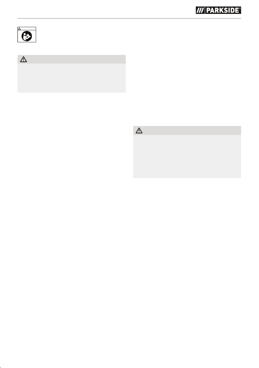
Safety instructions for the use
of compressed air appliances
RISK OF INJURY!
► Disconnect the compressed air supply before
changing tools, adjusting and servicing.
► When undoing a connection, always hold the
compressed air hose firmly in your hands.
Injuries may occur due to the compressed air
hose whipping back.
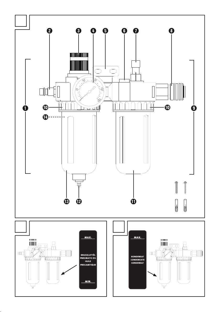
■ The compressed air maintenance unit must be
installed before it can be put safely into opera-
tion. A stable wall is suitable for mounting (with
screws).
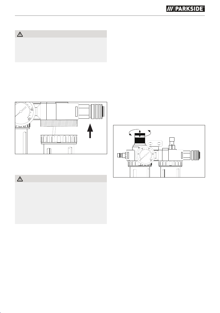
■ We recommend using only lubricants specified
by the manufacturer.
■ Never exceed the specified maximum pressure
values of the compressed air maintenance unit.
■ The compressed air maintenance unit may only
be connected to a compressed air source which
does not exceed the working pressure of 8 bar.
■ Do not place the compressed air lines near
heat, oil or sharp edges.
■ The compressed air maintenance unit may only
be operated in conjunction with a compressed
air compressor. The use of other compressed air
sources, such as a compressed air cylinder, is
prohibited. There is a risk of fire and/or explo-
sion.
■ Make sure that you keep children and people
with limited physical or mental abilities away
from the compressed air maintenance unit and
connected compressed air tools.