PASCO ME-6989 User manual

®
Physics Structures Set
ME-6989
Instruction Manual
012-10658A
*012-10658A*

Physics Structures Set Table of Contents
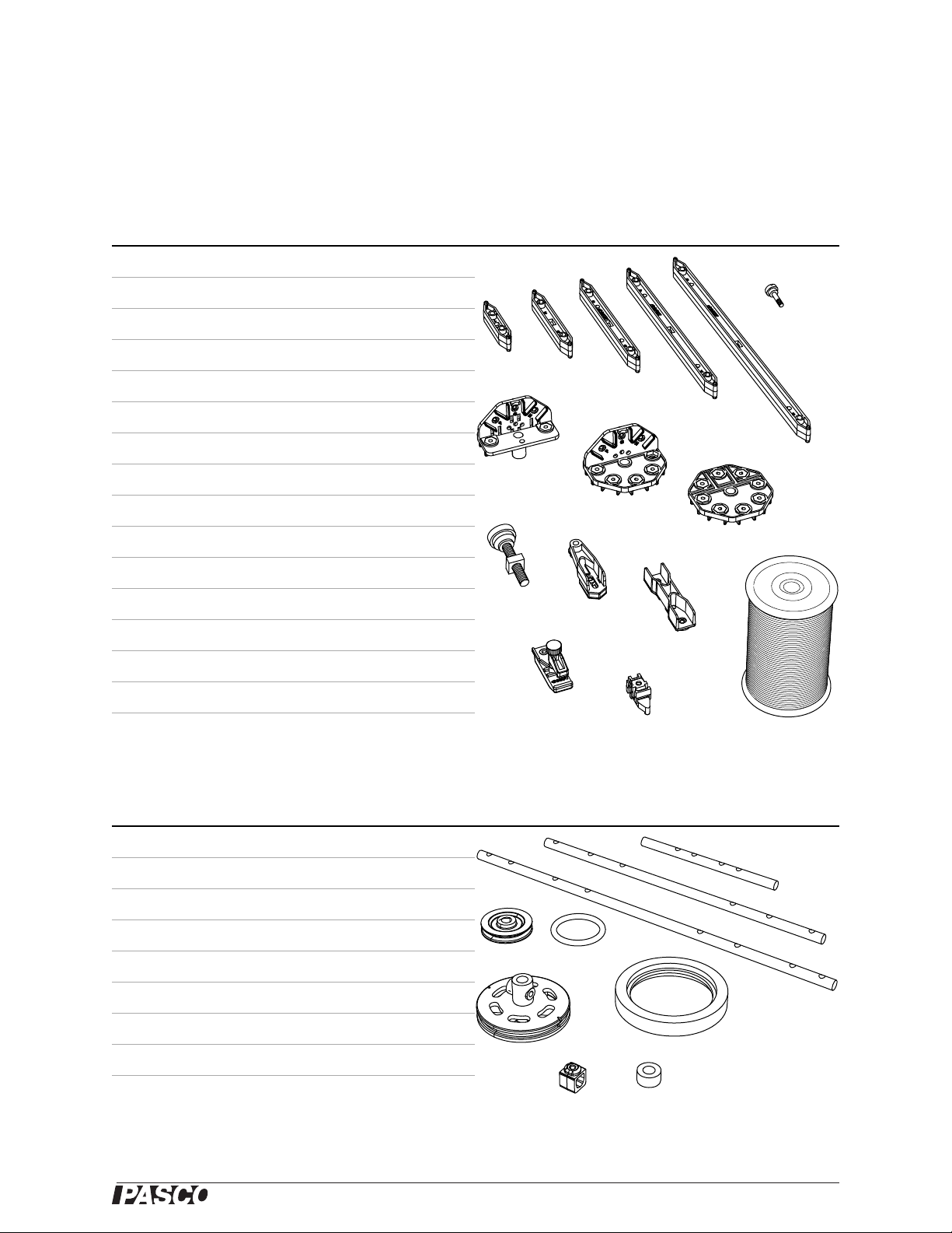
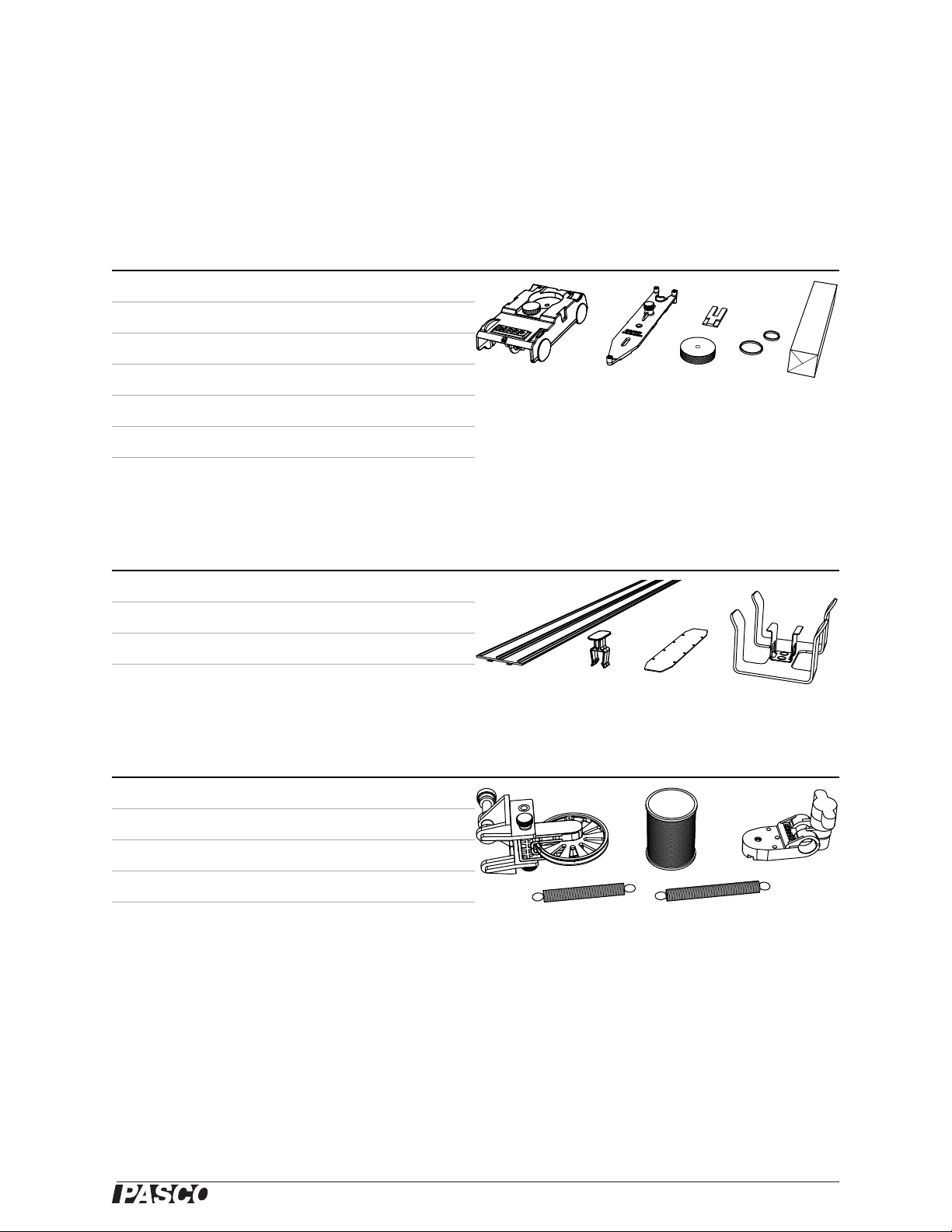
Included parts . . . . . . . . . . . . . . . . . . . . . . . . . . . . . . . . . . . . . . . . . . . . . . . . . . . . . . . . .1
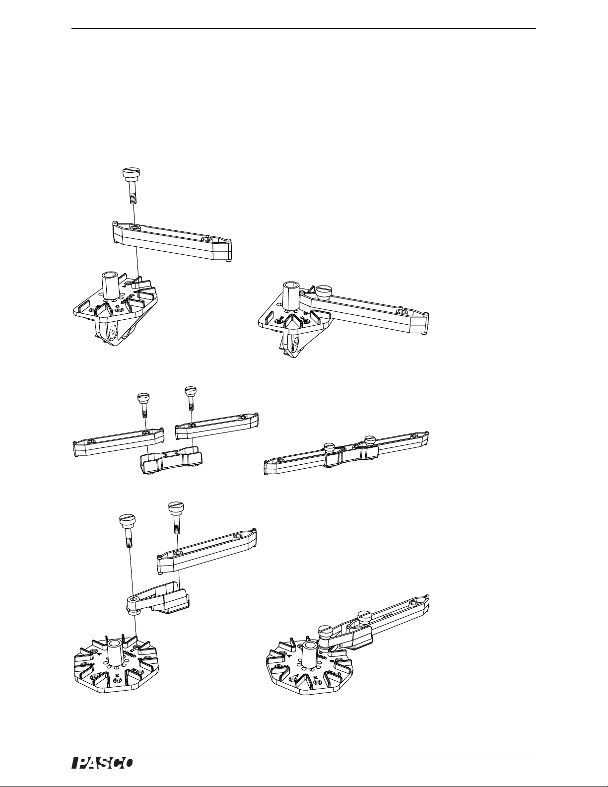
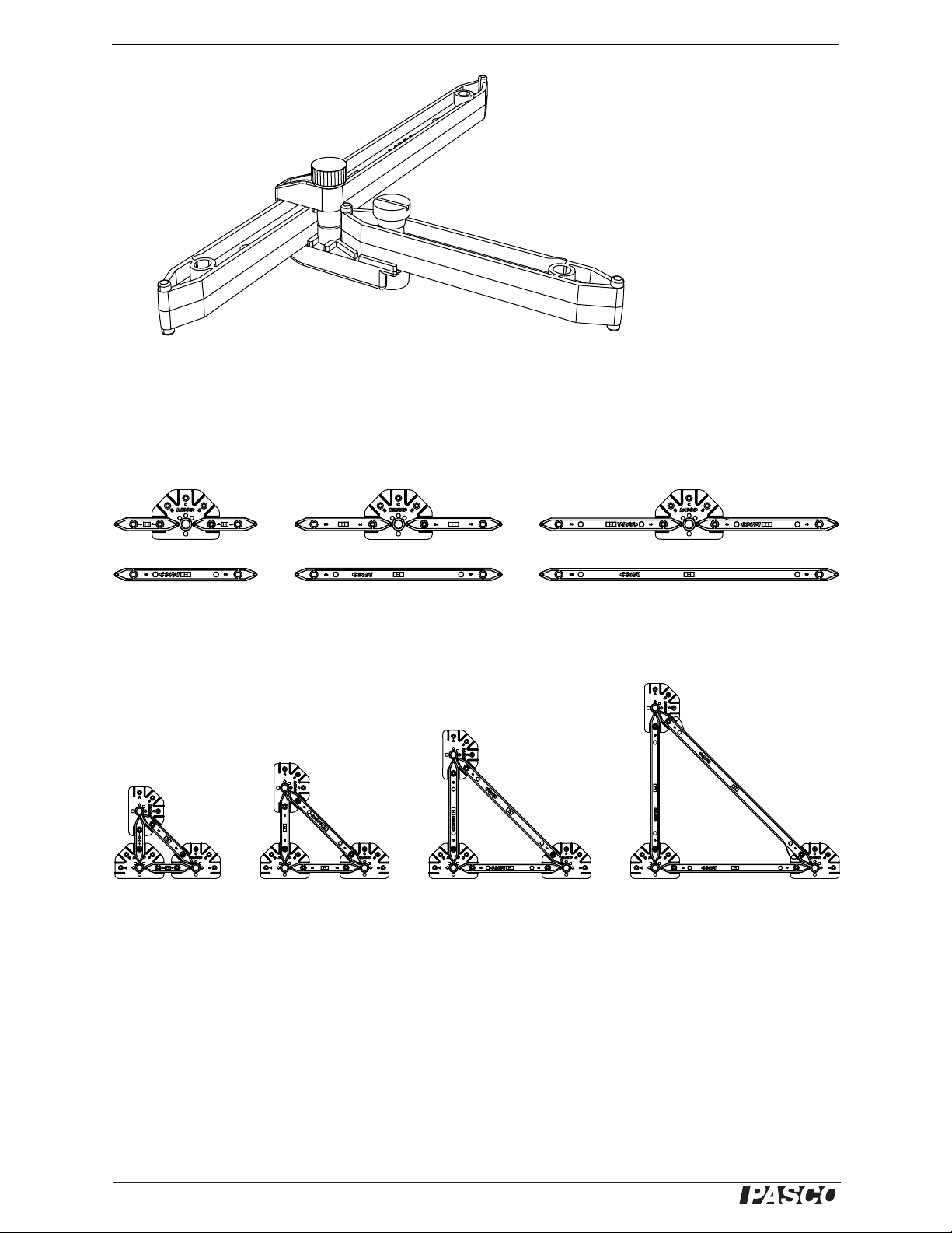
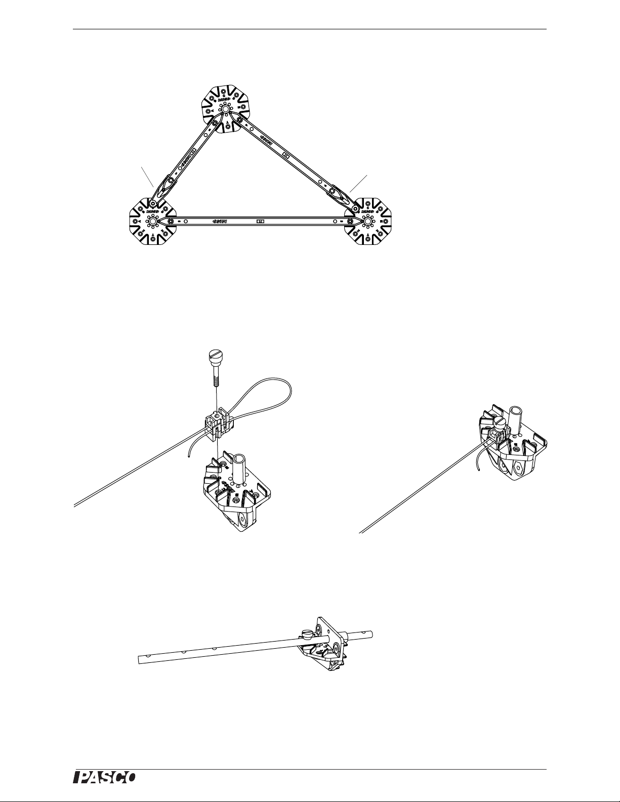
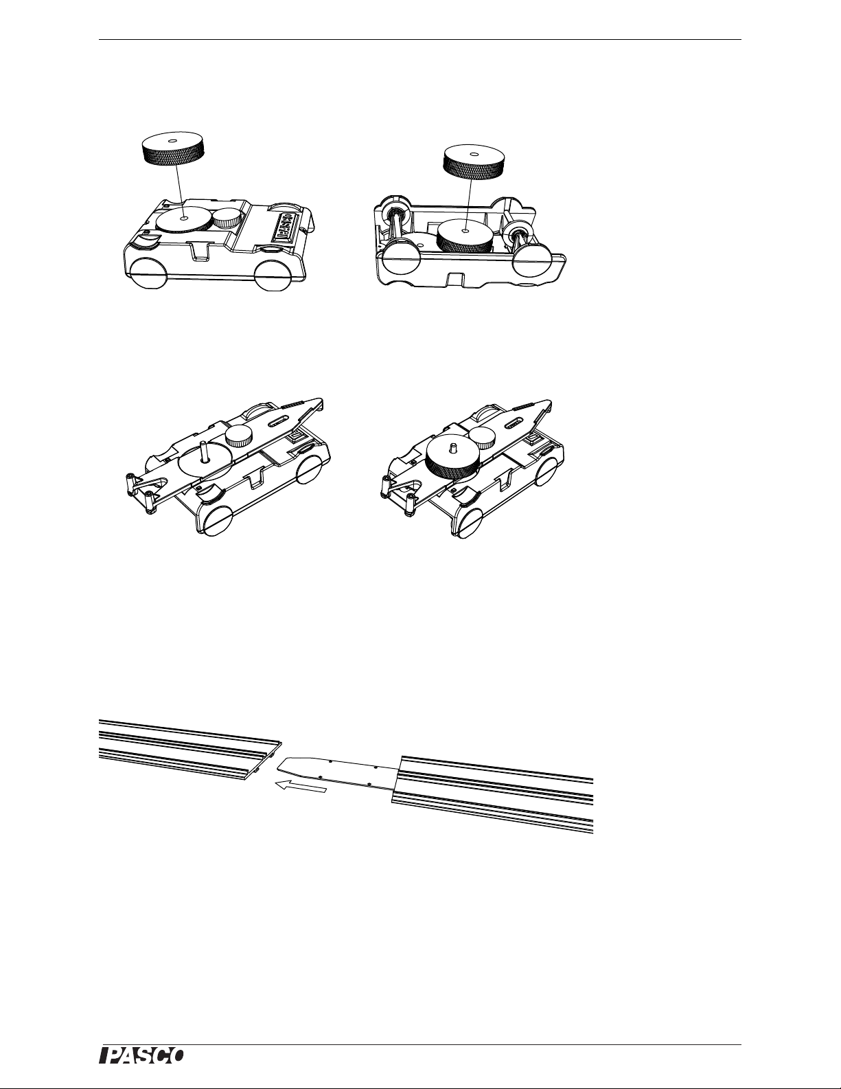
About the parts. . . . . . . . . . . . . . . . . . . . . . . . . . . . . . . . . . . . . . . . . . . . . . . . . . . . . . . . .3
Recommended additional equipment . . . . . . . . . . . . . . . . . . . . . . . . . . . . . . . . . . . . . . 10
Replacement parts and spares sets . . . . . . . . . . . . . . . . . . . . . . . . . . . . . . . . . . . . . . . 11
About the experiments. . . . . . . . . . . . . . . . . . . . . . . . . . . . . . . . . . . . . . . . . . . . . . . . . . 12
Experiment 1: Acceleration on an inclined plane . . . . . . . . . . . . . . . . . . . . . . . . . . . . . . 13
Experiment 2: Newton’s second law . . . . . . . . . . . . . . . . . . . . . . . . . . . . . . . . . . . . . . . 17
Experiment 3: Projectile motion . . . . . . . . . . . . . . . . . . . . . . . . . . . . . . . . . . . . . . . . . . . 21
Experiment 4: Forces in an Elevator . . . . . . . . . . . . . . . . . . . . . . . . . . . . . . . . . . . . . . . 25
Experiment 5: Roller Coaster. . . . . . . . . . . . . . . . . . . . . . . . . . . . . . . . . . . . . . . . . . . . . 29
Experiment 6: Centripetal force . . . . . . . . . . . . . . . . . . . . . . . . . . . . . . . . . . . . . . . . . . . 35
Experiment 7: Impulse and momentum . . . . . . . . . . . . . . . . . . . . . . . . . . . . . . . . . . . . . 39
Experiment 8: Physical Pendulum . . . . . . . . . . . . . . . . . . . . . . . . . . . . . . . . . . . . . . . . . 43
Experiment 9: Resonance . . . . . . . . . . . . . . . . . . . . . . . . . . . . . . . . . . . . . . . . . . . . . . . 47
Experiment 10: Work and energy . . . . . . . . . . . . . . . . . . . . . . . . . . . . . . . . . . . . . . . . . 51
Other experiments . . . . . . . . . . . . . . . . . . . . . . . . . . . . . . . . . . . . . . . . . . . . . . . . . . . . . 57
Appendix: DataStudio set-up notes . . . . . . . . . . . . . . . . . . . . . . . . . . . . . . . . . . . . . . . . 65
Teachers’ notes and sample data . . . . . . . . . . . . . . . . . . . . . . . . . . . . . . . . . . . . . . . . . 67
Technical Support . . . . . . . . . . . . . . . . . . . . . . . . . . . . . . . . . . . . . . . . . . . . . . . . . . . . . 74

Physics Structures Set
ME-6989
®
1
Included parts
Structure parts1Quantity
1. #1 beams 16
2. #2 beams 16
3. #3 beams 36
4. #4 beams 36
5. #5 beams 16
6. Screws 150
7. Half-round connectors 28
8. XYZ connectors 6
9. Flat round connectors 6
10. 1/4-20 thumbscrews 6
11. 1/4-20 nuts 6
12. Angle connectors 24
13. Straight connectors 24
14. Sliding connectors 12
15. Cord tensioning clips 32
16. Braided nylon cord, 70 m spool 1
1For replacement parts see PASCO parts ME-6993, ME-6990, ME-6997, ME-6999A, and ME-6996,
12345
6
7
8
9
10
11
12
13
14
15 16
Axles and wheels1Quantity
17. Long axles 2
18. Medium axles 2
19. Short axles 2
20. Pulleys 12
21. O-rings 12
22. Wheels 4
23. Tires 4
24. Collets 24
25. Spacers 12
1For replacement parts see PASCO part ME-6998A
17 18 19
20
21
22
23
24 25

®
2
Cars and car parts1Quantity
26. Minicars with thumbscrews 2
27. Minicar bumpers with thumbscrews 2
28. Photogate flags 2
29. Car masses, 0.04 kg 2
30. #8 rubber bands 24
31. #10 rubber bands 24
32. Clay 1
1For replacement parts see PASCO parts ME-6995 and ME-9813
26 27 28
29
30
31
32
Track and track parts1Quantity
33. Track, 3 m 1
34. Track clips 24
35. Track coupler 1
36. Starter bracket 1
1For replacement parts see PASCO parts ME-9814 and ME-6995
34
33 35
36
Other parts1Quantity
37. Clamp-on Super Pulley 1
38. Nylon thread, 130 m spool 1
39. Springs, approximately 2 N/m 4
40. Springs, approximately 1 N/m 4
41. Rod clamps 2
1For replacement parts see PASCO parts ME-9875, ME-9835, ME-9448A, and ME-6986
37 38
39 40
41

®
Model No. ME-6989 About the parts
3
About the parts
Structure parts
Assembling beams and connectors
Create structures by using thumbscrews to attach beams and connectors. Some of the
ways to assemble beams and connectors are illustrated below:
Connecting a beam to a half-round connector
Connecting two beams with a straight connector
Connecting a beam to a flat round connector with an angle connector. The angle
connector allows adjustment to both the angle and length of the beam.

®
Physics Structures Set About the parts
4
Connecting two beams with a sliding connector. The larger thumbscrew only needs to
be loosened, never completely removed from the sliding connector.
About beam lengths and triangles
When joined at a 180° angle with a connector, two identical short beams have a
combined length equal to one longer beam.
Isosceles right triangles, which contain only 90° and 45° angles, can be made using
the combinations of beams illustrated below.
#1 #1 #2 #2 #3 #3
#3 #4 #5
#1
#1
#2
#2
#3
#3
#4
#4 #5
#4
#3
#2

®
Model No. ME-6989 About the parts
5
To make triangles with angles other than 90° and 45°, use two or more angle
connectors. Angle connectors allow both the length and angle to vary.
Example of a triangle using angle connectors
Attaching cords
Use cord tensioning clips to attach cords to connectors. The clips allow the length
tension of the cord to be adjusted easily. Note that each clip consists of two loosely
captured parts that are not meant to be separated.
Axles and wheels
Examples showing uses of axles, pulleys, and wheels are illustrated below. See the
experiments in this manual for other examples.
Axle connected to a half-round connector with a screw
angle
connector
angle
connector

®
Physics Structures Set About the parts
6
Wheel connected to an axle with a screw
This wheel is free to rotate on the axle attached to two half-round connectors.
This pulley is free to rotate on the axle and is held in place by the collets
Mounting a tire on a wheel and an o-ring on a pulley
Cars and car parts
The three-wheeled minicar is designed to run on the included track.
If you are using a photogate to measure the speed of the car, attach the photogate flag
as pictured. The flag will interrupt the photogate twice as the car passes, allowing the
speed to be calculated.

®
Model No. ME-6989 About the parts
7
You can increase the mass of the car by placing a 40 g mass in the circular indentation
on the top of the car or by using the thumbscrew to attach the mass to the underside of
the car.
Use the bumper attachments and rubber bands to demonstrate collisions or to couple
two cars together as shown. A small amount of clay can be attached to a bumper to
achieve an inelastic collision. The 6-32 thumbscrew serves as a post for holding a
mass placed on top of the car.
Track and track parts
The flexible track is about 305 cm long and can be cut into shorter pieces. For the
experiments in this manual, cut the track into two pieces of 90 cm and 215 cm. See
“Replacement parts and spares sets” on page 11 for information about ordering
additional track.
Use the track coupler to join two pieces of track.
The track clips to connect the track to the structure beams. Attach the clips to the
channel on the underside of the track with a quarter twist as shown.

®
Physics Structures Set About the parts
8
Use the starter bracket to help align the wheels of the car on the track. Squeeze the
clip of the starter bracket and insert it into the channel on the underside of the track.
Slide the bracket along the track to the desired position.
Drop the car into the bracket as shown.
When properly aligned on the track, the front wheel of the car runs in the center
groove of the track, and the two back wheels run outside the side ridges.

®
Model No. ME-6989 About the parts
9
Super Pulley
There are many ways to use the Super Pulley with the structure components. One
method is to clamp it to an XYZ connector as illustrated.
Springs
The set includes eight spring: four with a spring constant of approximately 1 N/m,
and four of approximately 2 N/m. You can connect a spring to a car as illustrated.
An axle attached to an XYZ or half-round connector can be used to attach a spring to
a structure.

®
Physics Structures Set Recommended additional equipment
10
Rod Clamps
Use a rod clamp to attach a structure beam to any 12.7 mm diameter rod.
Recommended additional equipment
In addition to the Physics Structures Set, the experiments in this manual require the
equipment in the above table. See the experiment instructions starting on page 13 for
details on how this equipment can be used with the Physics Structures Set.
Equipment Part number
Recommended
quantity
Load Cell and Dual Amplifier Set PS-2206 1
100 N Load Cell PS-2200 1
5 N Load Cell PS-2201 1
Photogate Head ME-9498A 2
Digital Adapter PS-2159 1
Rotary Motion Sensor PS-2120 1
Mass and Hanger Set ME-8979 1
Large Slotted Mass Set ME-7566 1
Aluminum Table Clamp ME-8995 2
60 cm Long Threaded Rod ME-8977 3
PASOPORT Interface various, see www.pasco.com

®
Model No. ME-6989 Replacement parts and spares sets
11
Replacement parts and spares sets
Replacement parts
Road Bed Spares ME-6995
Mini Cars (Set of 3) ME-9813
Super Pulley with Clamp ME-9448A
Roller Coaster Track ME-9814
Road Bed Spares ME-6995
Structure Set Screws ME-6994
Truss Set ME-6990
Truss Set Members ME-6993
Full Round and XYZ Connector Spares ME-6997
Angle Connector Spares ME-6999A
Axle Spares ME-6998A
Cord Lock Spares ME-6996
Black Thread (3 pack) ME-9875
Light Duty Spring Set ME-9835
Structures Rod Clamp ME-6986

®
Physics Structures Set About the experiments
12
About the experiments
The experiments starting on page 13 show examples of how the set can be used to
study kinematics, momentum, energy, rotation, and other physics concepts. The first
ten experiments are presented in copy-ready format followed by several more
suggested experiments. Teachers’ notes and sample data for the copy-ready
experiments appear on pages 67–73.

®
Model No. ME-6989 Experiment 1: Acceleration on an inclined plane
13
Experiment 1: Acceleration on an inclined plane
Introduction
For this lab, you will build an inclined track on which the car is free to travel. Using
two photogates and a flag attached to the car, you will measure the car's velocity at
two points. Assuming constant acceleration, you can calculate the acceleration of the
car:
a= Δv/Δt
Where Δvis the change in velocity from one photogate to the next, and Δtis the time
elapsed as the car travels between gates.
Required equipment from Physics Structures Set Quantity
#1 beams 4
#2 beams 10
#3 beams 14
#5 beams 12
Half-round connectors 11
XYZ connectors 5
Flat round connectors 2
Sliding Connectors 12
Track clips 10
Track (90 cm length) 1
Car 1
Flag 1
Starter bracket 1
#10 Rubber band 1
Spacers 2
1/4-20 thumbscrews 2
Other required equipment Suggested Model Number
Photogates 2 ME-9498A
Interface or data logger 1 various
Digital adapter (if using a PASPORT interface) 1 PS-2159

®
Physics Structures Set Experiment 1: Acceleration on an inclined plane
14
Building the apparatus
Follow the steps below to build this track.
1. Build the sides of the structure as illustrated below.
2. Use 14 #3 beams as struts to connect the two sides.
3. Clip the track to the upper struts using 10 track clips.
4. Attached the starter bracket to the track.
5. Build two photogate brackets as illustrated (right) and attach them to the
structure.
6. Stretch a rubber band between the posts at the lower end of the track to form a
bumper.
photogate
photogate
car
starter bracket
rubber-band
bumper
#1
#1
#2
XYZ
connector
sliding
connectors
half-round
connector
#5
#5
#5
#5
#5
#5
#2 #2 #2
photogate
1/4-20
thumbscrew
flat round
connector
#2
spacer

®
Model No. ME-6989 Experiment 1: Acceleration on an inclined plane
15
7. Attach the photogate flag to the car.
Sensor setup
You will use the photogates to measure the acceleration of the car. As the double-flag
on the car passes through each photogate, the logic state of the photogate pulses low
twice, as illustrated.
Connect the photogates to your computer interface (or other timing device). Set up
the software to record and display the logic states of both photogates as a function of
time (see note 1 on page 65).
Pre-lab questions
1. The distance between the leading edges of the double flag is d. In terms of d, Δt1
and Δt2, write equations for the velocity (v1) of the car as it passes through the
first photogate, and the velocity through the second photogate (v2).
2. In terms of v1, v2, and Δt3, write an equation for the acceleration of the car (a).
Assume ais constant between the photogates.
3. What are the forces acting on the car? Draw a free-body diagram.
4. How will increasing the angle of the track affect the acceleration of the car?
Explain your reasoning.
5. Keeping the track at a constant angle, how will increasing the mass of the car
affect the acceleration? Explain your reasoning.
6. Keeping the track at a constant angle, how will changing the initial velocity or
starting point of the car affect the acceleration? Explain your reasoning.
7. Assuming that there is no friction acting on the car, write an equation relating the
acceleration of the car (a) to the angle of the track (θ).
8. If you plot aversus sin(θ), what value would you expect the slope of the graph to
be? Explain your reasoning.
Procedure
1. Start data recording.
Δt1
Δt3
Δt2
Photogate 1
Logic State
Photogate 2
Logic State
high
low
high
low

®
Physics Structures Set Experiment 1: Acceleration on an inclined plane
16
2. Place the car in the starter bracket and let it roll down the track through both
photogates. Stop the car before it bounces back through the photogates.
3. Stop data recording.
4. From your recorded photogate data, determine Δt1, Δt2, and Δt3. Calculate v1,
v2, and a. Write all of these in a table.
5. Use a meter stick to measure the “rise” and “run” of the track. Calculate the
angle, θand write it in your table.
6. Change the angle of the track and repeat steps 1 through 5. Record data for five
different angles.
Analysis
1. Calculate the acceleration, a, for each track angle and write it in your table.
2. Calculate sin(θ) for each track angle and write it in your table.
3. Make a graph of aversus sin(θ). What is the slope of the best-fit line? Is the
value of the slope what you expected? If not, discus why.
Further study
Predict how your results would change if you repeated the experiment with each of
the following changes. Explain your predictions.
• Add mass to the car.
• Start the car in a different location on the track.
• Change the distance between the photogates.
• Start the cart at the bottom of the incline and launch it up hill.
Test one of your predictions.

®
Model No. ME-6989 Experiment 2: Newton’s second law
17
Experiment 2: Newton’s second law
Introduction
For this lab, you will build a track with a pulley at one end. A thread running over the
pulley will connect the car to a hanging mass. A photogate on the pulley will allow
you to record the speed of the car and hanging mass as they move.
You will measure the acceleration of the car for various values of hanging mass. Then
you will use your data do predict the hanging mass that will cause the car to move at
constant velocity.
Required equipment from Physics Structures Set Quantity
#2 beams 10
#3 beams 19
#5 beams 12
Half-round connectors 11
XYZ connectors 6
Flat round connector 1
Sliding connectors 12
Track clips 10
Track (90 cm length) 1
Car 1
Car masses 2
Starter bracket 1
Super Pulley 1
#10 Rubber band 1
Spacer 1
1/4-20 thumbscrew 1
Thread (about 1 m) 1
Other required equipment Suggested Model Number
Mass and hanger set 1 ME-8979
Photogate 1 ME-9498A
Interface or data logger 1 various
Digital adapter (if using a PASPORT interface) 1 PS-2159

®
Physics Structures Set Experiment 2: Newton’s second law
18
Building the apparatus
Follow the steps below to build this track.
1. Build the sides of the structure as illustrated below.
2. Use 14 #3 beams as struts to connect the two sides.
3. Build a pulley bracket as illustrated (right) and attach it to the end of the
structure.
4. Clip the track to the upper struts using 10 track clips. Adjust the track to make it
as straight as possible.
5. Attached the starter bracket to the track.
photogate and
super pulley
mass
hanger
car
starter bracket
thread
rubber-band
bumper
sliding
connectors
#5
#2
XYZ
connector
half-round
connector
#3
#3
#2
#5
#5
#2
#5
#5
#5
#2
XYZ
connector
#3
Super
Pulley
Table of contents
Other PASCO Educational Equipment manuals
Popular Educational Equipment manuals by other brands

ClassMate
ClassMate BOLTX501 user guide

Buki
Buki 8367 manual

Nasco Healthcare
Nasco Healthcare IV TRAINING ARM AND HAND instruction manual

Simulaids
Simulaids RANDY 9000 Instruction and Care Manual

Nasco Healthcare
Nasco Healthcare Flexible Rescue Randy instruction manual

Rompa
Rompa Rainbow Bumpas with Vibration manual

PHYWE
PHYWE Cobra SMARTsense 12922-00 operating instructions

Abra
Abra AK-72 manual

Eastern Voltage Research
Eastern Voltage Research Joule Thief 1.0 instruction manual

H-TEC Education
H-TEC Education D201 operating instructions

Sony
Sony KOOV Basic user's guide

Simulaids
Simulaids Forceps/Vacuum Delivery OB Manikin Instructions for use