PHYWE Cobra SMARTsense 12922-00 User manual

1
www.phywe.com, © All rights reserved 12922-00 / 0421
Operating instruc-
tions
Cobra SMARTsense Conductivity
12922-00
PHYWE Systeme GmbH & Co. KG
Robert-Bosch-Breite 10
D–37079 Göttingen
Telefon +49 (0) 551 604–0
Fax +49 (0) 551 604–107
E-mail info@phywe.de
Internet www.phywe.com
The unit complies
with the applicable
EC-guidelines
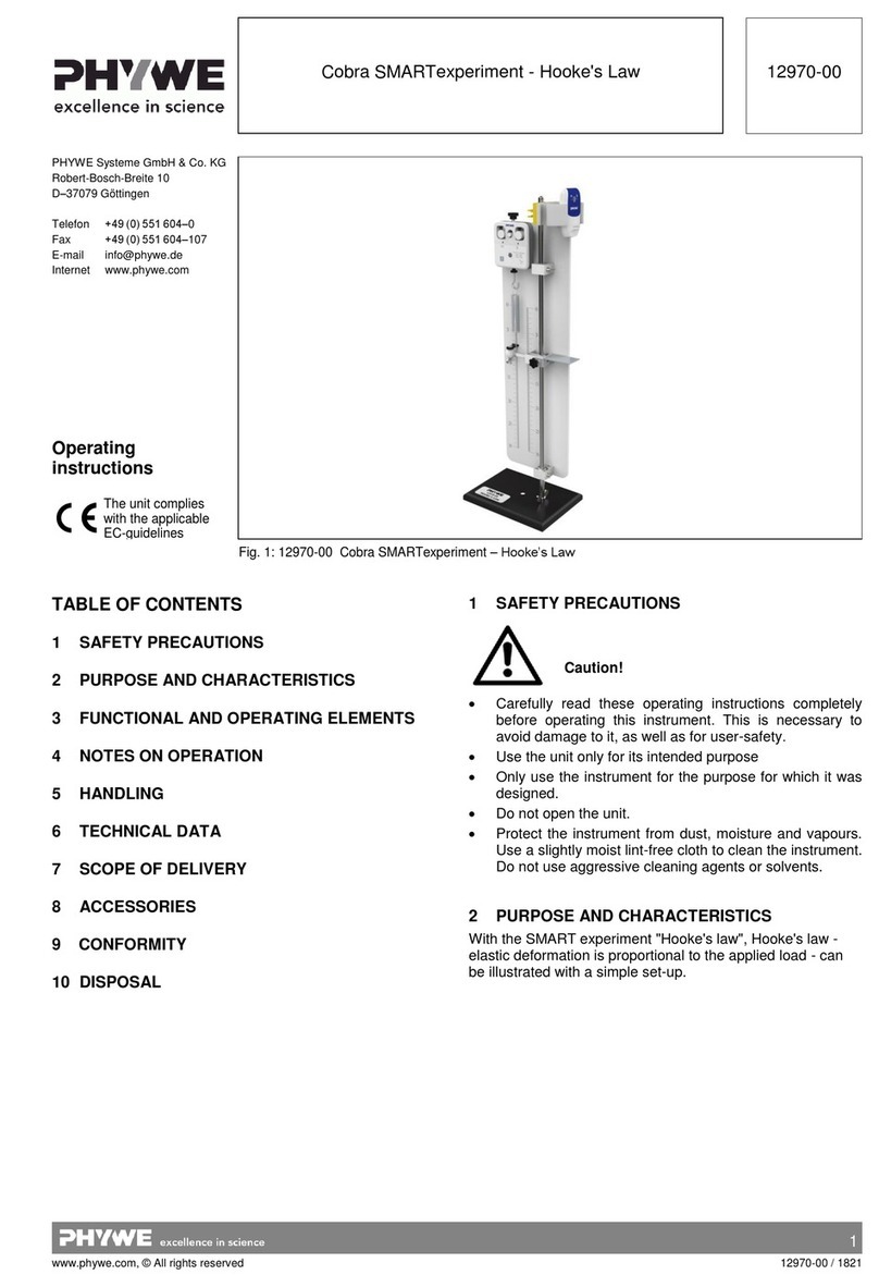
Fig. 1: 12922-00 Cobra SMARTsense Conductivity
TABLE OF CONTENTS
1SAFETY PRECAUTIONS
2PURPOSE AND CHARACTERISTICS
3FUNCTIONAL AND OPERATING ELEMENTS
4NOTES ON OPERATION
5 HANDLING
6TECHNICAL DATA
7SCOPE OF DELIVERY
8ACCESSORIES
9 CONFORMITY
10 DISPOSAL
1 SAFETY PRECAUTIONS
Carefully read these operating instructions completely
before operating this instrument. This is necessary to
avoid damage to it, as well as for user-safety.
Only use the instrument for the purpose for which it was
designed.
Only use the instrument in dry rooms in which there is no
risk of explosion.
Protect the instrument from dust, moisture and vapours.
Use a slightly moist lint-free cloth to clean the instrument.
Do not use aggressive cleaning agents or solvents.
Take care that no liquid penetrates in through the hous-
ing openings, as such penetration would result in dam-
age to Sensor.
Do not open the unit.
2 PURPOSE AND CHARACTERISTICS
The sensor is used for measuring the conductivity of aqueous
solutions as well as temperature values and for transferring
the values to a terminal device, e.g. a tablet computer,
smartphone, etc., via Bluetooth.
Caution!

2
www.phywe.com, © All rights reserved 12922-00 / 0421
3 FUNCTIONAL AND OPERATING ELEMENTS
3.1 Operating elements
The sensor has an on-button and two LEDs for indicating the
Bluetooth and battery charge status.
On-button
Press the on-button for more than 3 seconds to switch the
sensor on and off
Bluetooth-LED
Flashing red every 2 seconds
Not connected
Flashing green every 2 seconds
Connected to the ter-
minal device
Flashing green every 4 seconds
Running measurement
Battery charge LED
Flashing red every 5 seconds
Low battery
3.2 Measurement inputs
The front of the sensor is equipped with a fixed conductivity
measuring cell with an integrated temperature sensor.
4 NOTES ON OPERATION
This device fulfils all of the technical requirements that are
compiled in current EC guidelines. The characteristics of this
product qualify it for the CE mark.
The individual connecting leads are each not to be longer
than 2 m.
The instrument can be so influenced by electrostatic charges
and other electromagnetic phenomena (HF, bursts, indirect
lightning discharges) that it no longer works within the given
specifications. Carry out the following measures to reduce or
eliminate the effect of such disturbance: Ensure potential
equalization at the PC (especially with Laptops). Use screen-
ing. Do not operate high frequency emitters (e.g. radio
equipment or mobile radiotelephones) in the immediate vicini-
ty. When a total failure of the instrument occurs, unplug it and
plug it back in again for a reset.
5 HANDLING
This section describes the start-up of the sensor and the re-
cording of measurement data. Please read this section thor-
oughly in order to avoid failures or operating errors.
5.1 Start-up
Switch the sensor on by pressing the on-button for more than
3 seconds. The Bluetooth LED lights up red. Start the soft-
ware and select the sensor.
There is a 9-digit code
on the back of the sen-
sor (Fig.2). The last 4
digits of the code are
displayed as the sensor
name in the software
(Fig.3). This enables
the precise assignment
of the sensors within
the software.
Fig. 2
Fig. 3
5.2 Recording of conductivity values
To measure the conductivity of the various media, the meas-
uring head of the conductivity measuring cell is completely
plunged into the medium to be measured. If a whole series of
different solutions is to be measured, we recommend starting
with the solution with the lowest conductivity. Since some of
the sample material is always carried over to the next sam-
ple, this method ensures that a potential error remains on an
acceptable level as the contamination of a solution with a
high level of conductivity with traces of a solution with a low
level of conductivity leads to a smaller relative error than the
other way round. In any case, the measuring head and elec-
trodes must be rinsed with pure (demineralised or distilled)
water when switching from one sample to another.
The solution should always remain slightly in motion during
the measurement. This can be realised by stirring the liquid
with a magnetic stirrer or similar or by moving the measuring
probe carefully to and fro.
5.3 Maintenance and cleaning of the measuring probe
In general, conductivity measuring cells are not subject to
ageing. However, the measuring electrode can be corroded
and, thereby, damaged by certain media (e.g. strong acids
and lyes). This is why all of the measuring cells should be
rinsed thoroughly with clean (demineralised or distilled) water
whenever they have been used. If the measuring electrode is
contaminated with grease or oil, it can be cleaned with warm
water and a commercially available household detergent.
The measuring cell comes supplied with a protective cap
which is filled with distilled water. Do not allow the measuring
cell to dry out. This might cause the platinum black to crum-
ble off which, in turn, would change the cell constant. This is
why it should always be stored in pure water. When cleaning
the measuring cell, avoid any mechanical stress on the
measuring electrodes.
5.4 Calibration
In general, the conductivity measuring cell does not need to
be calibrated if it is maintained properly.
If a calibration needs to be carried out, it is a two-point cali-
bration. The calibration data are entered via the measure-
ment software (App).
First calibration point
Dip the measuring cell into distilled/deionised water or ultra-
pure water.
Conductivity at 25°C
Ultra-pure water
0.055 µS/cm
Deionised water
1 µS/cm
Enter the value (see the table) as set point 1 and send it to
the sensor.
Measuring electrodes
Protective cap

3
www.phywe.com, © All rights reserved 12922-00 / 0421
Second calibration point
Dip the measuring cell into a calibration solution (e.g. 47070-
02) and enter the conductivity value of the calibration solution
as set point 2. Send this value to the sensor as well.
The calibration data are now stored in the sensor.
5.5 Replacing the battery
Remove the battery
Open the sensor by turning the screw
cap on the back of the sensor
counterclockwise e.g. with a coin.
Fig. 4
Carefully lift the battery out of
its socket with the aid of a
small screwdriver or small
scissors. Insert the screw-
driver as shown in Fig. 5.
Fig. 5
Insert new battery
Slide the battery under the golden metal nose (Fig.6-1). Make
sure that the battery is completely under the metal nose and
is pushed completely to the upper edge.
Press the battery into the socket
by applying light pressure on the
opposite side.
The battery slides under the two
plastic lugs (Fig. 6-2), which can
also be noticed by a short "click”.
Fig. 6
Before closing the lid, make sure that
the seal in the lid is not bent and lies
cleanly on the edge of the lid. After
closing, turn the lid clockwise to
tighten it.
Fig. 7
6 TECHNICAL DATA
Operating temperature range: 5 - 40°C
Rel. humidity < 80%
Conductivity
Measuring range
Resolution
0…20000 µS/cm
8 µS/cm
Temperature
Measuring range
Resolution
Max. date rate
Battery type
Max. wireless range (open field)
IP category
Dimensions (width x height x depth)
0…100°C
0.1 °C
10 Hz
CR2032
30 m
IP67
220 x 42 x 24 mm
Weight
60 g
7 SCOPE OF DELIVERY
The extent of delivery is as follows
Cobra SMARTsense Conductivity 12922-00
Protective cap for measuring cell
Operating instructions
8 ACCESSORIES
The following accessories are available:
Button cell CR2032, 3V 07922-15
Standard solution1413 μS/cm, 460 ml 47070-02
USB-Bluetooth-Adapter 07936-00
Software measureLAB 14580-61
Free measureApp available from supplier portals
iOS
Android
Windows
9 CONFORMITY
2
1
PHYWE Systeme GmbH & Co.KG hereby
declares that the radio system type 12922-
00 complies with the 2014/53/EU directive.
The complete text of the EC Declaration of
Conformity is available at the following In-
ternet address:
www.phywe.com/en/ec-declaration

4
www.phywe.com, © All rights reserved 12922-00 / 0421
10 DISPOSAL
The packaging mainly consists of environmentally-friendly
materials that should be returned to the local recycling sta-
tions.
PHYWE Systeme GmbH & Co. KG
Abteilung Kundendienst
Robert-Bosch-Breite 10
D–37079 Göttingen
Telefon +49 (0) 551 604-274
Fax +49 (0) 551 604-246
Do not dispose of this product with normal
household waste. If this unit needs to be
disposed of, please return it to the address
that is stated below for proper disposal
Other PHYWE Educational Equipment manuals
Popular Educational Equipment manuals by other brands

Eastern Voltage Research
Eastern Voltage Research Joule Thief 1.0 instruction manual

H-TEC Education
H-TEC Education A129 operating instructions

Experia
Experia IRiS Balance Beam instruction manual

Simulaids
Simulaids Economy Sani-Man DIRECTIONS FOR ASSEMBLY

Sony
Sony Vision Exchange PEQ-C100 System Integration & Services Guide

TruCorp
TruCorp AirSim Bronchi user manual