H-TEC Education D201 User manual

Operating Instructions
D201 - Exhibition Kit

2www.myhtec.com
Table of contents
03
03
03
04
06
07
08
11
12
14
15
15
15
The Exhibition Set
About these instructions
Safety information
Contents
Overview
Starting up
Operation
Technical Data
Troubleshooting
Shutting Down
Maintenance
Transportation & Storage
Disposal

www.myhtec.com 3
e Exhibition Set
The Exhibition Set offers the option of easily visualizing the functionality of hydrogen technology.
The model demonstrates that electrical energy (e.g. from renewable energy sources) can be
stored temporarily in the form of hydrogen, using electrolysis. This chemical energy can then be
made available again in an environmentally friendly way, using the fuel cell, should the demand
for electrical energy increase or should the primary energy source fail (e.g. wind, solar). All that is
needed for generating electricity are hydrogen and oxygen. Water is a by-product of this process.
These operating instructions document all process steps required for starting up and operating
the Exhibition Set.
We hope you enjoy many instructive hours with the Exhibition Set.
The team at,
H-TEC EDUCATION
About these instructions
• These operating instructions are intended for the supervisor in charge.
• These operating instructions have to be read and observed before use.
• These operating instructions have to be available for reference and have to be stored in a
safe place.
• All safety instructions must be observed.
• This product may only be put into operation and operated under the directions of the
responsible supervisor.
Safety information
Read and observe the general safety instructions included separately with this product before
using the product!
Product-specific safety information
The product may only be used:
• according to the intended use
• in compliance with all safety information
The components of this product feature freely accessible, live electric contact surfaces.
Connecting to an impermissible operating voltage may result in a fire hazard, a risk of electric
shock and damage to the components.
The product may only be operated under the constant supervision of an adult trained in the
handling of this product.
The product should only be operated in a display cabinet or similar if adequate ventilation with
an air velocity of 0.5m/s at the product is ensured. The operator should ensure this by taking
appropriate measurements.

4www.myhtec.com
Contents
1x Demonstration model
2x Overflow tanks
1x Solar module
1x Fuel cell gas flow indicator / Water trap
1x Fan module

www.myhtec.com 5
2x Cable Set
1x Companion text book
Additional tools required: 2.5mm hex key
Connection cables, 4mm, 50cm length, red
Connection cables, 4mm, 50cm length, black

6www.myhtec.com
Fig. 1: The demonstration model at a glance
Overview
The “Exhibition” demonstration model at a glance
The “Exhibition” demonstration model consists of an electrolyser, two water reservoirs and a fuel
cell, all mounted to a black base plate. When the electrolyser is supplied with electrical energy,
it produces hydrogen and oxygen from distilled water. The gases enter the fuel cell via the
water reservoir and a system of tubes where, provided a load (consumer) is connected, they are
converted back to water while electrical energy and heat are being generated. The demonstration
model is equipped with two 4 mm female connectors for connecting multilam (banana) plugs.
The individual components are shown in the following graphic.
Overflow tanks
Fuel cell
Base plate
FC gas flow
indicator
Base plate
Water reservoirs
Fuel cell connection
jacks for 4mm
banana plugs
Electrolyzer
connection jacks
for 4mm banana
plugs
Water outlets
with tube clamps
(concealed)

www.myhtec.com 7
Starting up
Fig. 2: Assembly
Assemble the demonstration model as shown in Figure 2.
Remove both locking screws by turning them counter-clockwise.
Place Gas Flow indicator below fuel cell, and attach tubes from fuel cell.
The preparation for storage and transportation is carried out in reverse order to assembly.
Do not yet connect the power supply to the electrolyzer.
Fig. 3: Filling
Distilled water
σ<2 μS/cm
Filling
Fill the water reservoir with distilled water, up to the -MAX- mark, and add water to Gas flow
indicator bowl. Note: Use only distilled water (σ<2 μS/cm) as shown in Figure 3.
Attach both overflow tanks to the water reservoir using a clockwise motion.
Close both tube clamps on the water outlets.

8www.myhtec.com
Operation
Fig. 4: Exhibition Set operation
A
B
C
D
Read and observe the general safety instructions.
Using the connecting cables, connect the propeller (A) with the respective connections (B) on
the fuel cell, while ensuring correct polarity (red = “+”, black = “-”).
Using the connecting cables, connect the solar module (C) with the respective connections
(D) on the electrolyzer, while ensuring correct polarity (red = “+”, black = “-”). If using an
alternative power source, make sure to comply with the electrical specifications as defined
in the technical data.
Provide the solar module with adequate direct sunlight or with light from a powerful,
concentrated electrical light source. The shadow of an individual module created by the light
mus not be projected onto another module. The water is split into hydrogen and oxygen at
a ration of 2:1. Gas production can be recognized by gas bubbles rising inside the water
reservoirs.
The Exhibition Set is now in operation. The propeller vane will start to rotate as soon as the
hydrogen and the oxygen reach the fuel cell. Warm-up takes approximately 5-10 minutes. If
the model is operated by solar module, and if lighting conditions are extremely poor, warm-
up may take longer.

www.myhtec.com 9
During operation, small amounts of water pass through the electrolyzer’s polymer electrolyte
membrane (PEM) from the oxygen side. This may cause the water level to rise on the
hydrogen side and fall on the oxygen side. In addition, distilled water is being consumed
during operation.
If the water level needs to be adjusted, gas production must be stopped. For this purpose,
remove the connecting cables on the power supply from the respective connections on the
electrolyser. To remove water, briefly open the tube clamp on the respective water outlet
(see Chapter “Shutting down”).
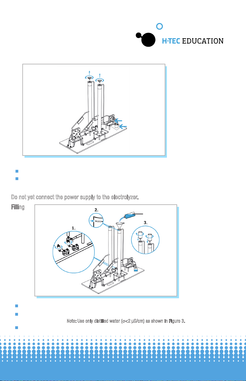
Always maintain the water levels in the water reservoirs between the -MAX- and the -MIN-
mark. For this reason, check and, if necessary, adjust the water level during operation.
Distilled water may be added (σ< 2 μS/cm) to the respective water reservoir with the
overflow tank in place.
Risk of injury from hydrogen ignition!
Damaged tubes or leaking connections may cause hydrogen to escape.
Hydrogen and hydrogen-air mixtures may ignite when in proximity to an ignition
source.
Check tubes and connections for damage before each setup and before each use.
Risk of injury from hot surfaces!
A diode on the underside of the base plate protects the electrolyzer against reverse
polarity. The protection diode becomes very hot in case of incorrect polarity. Touching
the protection diode may cause injuries.
When connecting the power supply, ensure the correct polarity of the electric
connections (red = “+”, black = “-”). Do not touch the protection diode.
Risk of injury from hot surfaces!
The surface of solar modules may become very hot during operation.
Touching the surface of the solar modules may cause injuries.
Do not touch the surface of the solar modules during operation. Let the surface of the
solar modules cool to at least 60 °C before disassembly or removal.
CAUTION
CAUTION
CAUTION
Risk of injury from hydrogen ignition!
During operation, small amounts of hydrogen are continuously released into the
atmosphere. Escaping hydrogen may ignite when in proximity to an ignition source.
Keep product away from ignition sources. Ensure ventilation in accordance with the
general safety instructions.
Risk of fire due to electrical overload.
Any operation beyond the electrical specifications will lead to excessive overheating
of the electrolyzer. This may cause a fire.
Never operate the electrolyzer beyond the electrical specifications stated in the
technical data.
CAUTION
CAUTION

10 www.myhtec.com
CAUTION
CAUTION
CAUTION
NOTE
CAUTION
Risk of damage due to electrical overload
Any operation beyond the electrical specifications will lead to irreparable damage to
the electrolyzer.
Never operate the electrolyzer beyond the electrical specifications stated in the
technical data.
Risk of damage due to insufficient distance to lamps
The solar module may become excessively hot or sustain irreparable damage if it is
too close to the lamp.
Observe the minimum distance defined by the manufacturer when operating solar
modules with lamps.
Risk of damage due to improper handling
Operating the electrolyzer using water with an electrical conductivity of
σ ≥2 μS/cm will cause irreparable damage to the electrolyzer. Only fill the
electrolyzer using distilled water with an electrical conductivity of σ<2 μS/cm.
Water in the fuel cell
Ensure that no water enters the fuel cell. A water film on the electrode surface may
suppress the reaction of hydrogen and oxygen in the fuel cell. In such cases, the
output of the fuel cell will be inadequate.
Risk of damage due to voltage
Applying voltage to a fuel cell or a solar module leads to irreparable damage to the
components.
Do not apply voltage to fuel cells and solar modules.

www.myhtec.com 11
Technical data
Exhibition model:
Electrolyzer:
Fuel Cell:
Accessories:
H x W x D:
Weight:
H2Production:
O2Production:
Permissible current:
Permissible operating voltage:
Electrode area:
Guide value for distilled water:
Permitted operating pressure:
H x W x D:
Short circuit current:
Open circuit voltage:
Power output:
Electrode area:
Permitted operating pressure:
H x W x D:
Water reservoir:
Solar module:
Load (fan):
700 x 300 x 1300 mm
4.8 kg
35 mL/min
17.5 mL/min
0 - 5 A
0 - 2.0 VDC
36 cm2
<2 μS/cm
0 - 20 mbar
100 x 100 x 40 mm
3.3 A
1 VDC
1.2 W
16 cm2
0 - 20 mbar
80 x 80 x 40 mm
approx. 500 mL / reservoir
2.0V / 1.0 A
10 mW

12 www.myhtec.com
Troubleshooting
Despite hydrogen and oxygen being produced, the load connected to the fuel cell is not working.
The fuel cell has low output.
The overflow tanks are not secured firmly in place.
The product requires a brief warm-up period before the gases produced by
the electrolyzer reach the fuel cell, where they are converted to water while
electrical energy and heat are being generated. Warm-up can take longer if
lighting conditions are extremely poor.
The load has not been connected correctly, or is not receiving any voltage.
The fuel cell was stored too dry, or for too long. A fuel cell with a dry Polymer
Electrolyte Membrane will lose power.
Water has entered the fuel cell during operation. This can cause a rapid decline
in performance.
Turn the overflow tanks clockwise, until they are secured firmly in place.
Wait the 5-10 minutes for the warm-up process to complete.
Check the connecting cables, and power supply.
Carefully nudge the propeller by hand to bypass the starting current.
Continue operation. The fuel cell automatically moistens itself during operation,
which will slowly let it reach its full capacity again.
Continue operation. Excess water will be expelled from the fuel cell during
operation. The fuel cell will slowly return to full capacity.
Possible Cause:
Possible Cause:
Possible Cause:
Possible Cause:
Possible Cause:
Solution:
Solution:
Solution:
Solution:
Solution:
Solution:

www.myhtec.com 13
With the solar module connected, no gas production takes place in the electrolyzer.
The fan does not work despite a supply voltage being present and the connecting cables
being connected correctly.
The output of the solar module is insufficient, despite adequate light intensity and the
connecting cables being connected correctly.
If the above-mentioned solutions do not eliminate the cause of the error, please contact
H-TEC EDUCATION.
Despite correct setup, the electrolyzer or the fuel cell is not working.
The light intensity is insufficient.
The fan is broken.
The solar module is defective.
No distilled water was used. The electrolyzer and/or the fuel cell has/have
sustained irreparable damage.
Operate the solar module using either adequate direct sunlight or concentrated
light from a powerful electrical light source. Energy-saving light bulbs,
fluorescent tubes etc. are unsuitable for the operation of solar modules.
Contact H-TEC Education
Possible Cause:
Possible Cause:
Possible Cause:
Possible Cause:
Solution:
Solution:
Solution:

14 www.myhtec.com
After disconnecting the power supply from the electrolyser, continue operating the fuel cell until
the connected load stops by itself. This allows some water to remain in the fuel cell, moistening
the PEM. In addition, this procedure also prevents that hydrogen is released unnecessarily.
Shutting down
Risk of injury from hydrogen ignition!
Escaping hydrogen may ignite when in proximity to an ignition source.
Prevent hydrogen from being released into the atmosphere. Completely use up all
hydrogen before dismantling.
CAUTION
Fig. 5: Emptying the
water reservoir
Disconnect the power supply from the connections on the electrolyser.
Any hydrogen present has to be consumed before draining the storage tanks.
To extend the water outlets, the tubes may be fitted to the water outlets.
Open both tube clamps on the water outlets.
Drain the water reservoir, as shown in Figure 5. The water must be disposed of correctly.
You must ensure that the power supply is disconnected from the connections on the
electrolyzer.
Close both tube clamps on the water outlets again.
Carefully remove any water drops from the product with a soft, lint-free cloth. This prevents
the formation of water stains. Do NOT use chemicals to clean.
Before putting the product into storage, observe the following points:

www.myhtec.com 15
The components of this product do not require maintenance. The following points should be
observed, however:
With regard to transport and storage of the product, the following points should be observed to
ensure a long service life. Transport and storage only:
Do not dispose of fuel cells and electrolysers as general household waste.
Maintenance
Transportation and storage
Disposal
Use fresh, distilled water (σ< 2 μS/cm) for each new start-up.
With the transport safety device in place (see Chapter “Assembly”)
Dry and dust-free
After operation, remove the water from the water reservoir.
In the original packaging
At temperatures from 4 °C to 50 °C
Protected from shock and vibrations
According to European regulations, used electric and electronic devices may no longer be
disposed of as unsorted household waste. The symbol of the crossed-out wheelie bin indicates
the requirement for separate disposal.
Your local waste management company can provide you with additional information about
disposal options.
Fire hazard from catalytic substances
The catalysts for the electrodes of fuel cells and electrolysers promote burning when
they come into contact with flammable substances. Avoid contact with hydrogen, alcohol
fumes or other organic fumes. Ensure correct disposal.
WARNING

© H-Tec Education, 2019. No part of this guide may be reproduced in whole or in part in any
manner without the express written permission of H-Tec Education. Subject to technical changes.
H-TEC EDUCATION
1902 Pinon Dr. Unit B
College Station, TX 77845
USA
Phone: +1 979-703-1925
Fax: +1 979-314-1122
Email: [email protected]
Website: www.myhtec.com
Table of contents
Other H-TEC Education Educational Equipment manuals
Popular Educational Equipment manuals by other brands

Enabling Devices
Enabling Devices Cheap Talk 4 Square Direct user guide

Sony
Sony Vision Exchange PEQ-C100 System Integration & Services Guide

Nasco
Nasco Life form LF01006U instruction manual

LEXIBOOK
LEXIBOOK EDU100i1 instruction manual

SPINNAKER
SPINNAKER STORY MACHINE manual

Pronounce
Pronounce PRO01 user guide