manuals.online logo
Brands
  1. Home
  2. •
  3. Brands
  4. •
  5. Paso
  6. •
  7. Speakers
  8. •
  9. Paso C36/6-T Service manual

Paso C36/6-T Service manual

1
DIMADIFORATURA-DRILLINGTEMPLATE
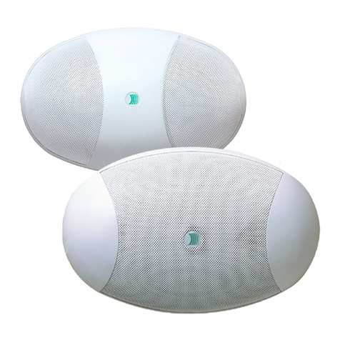
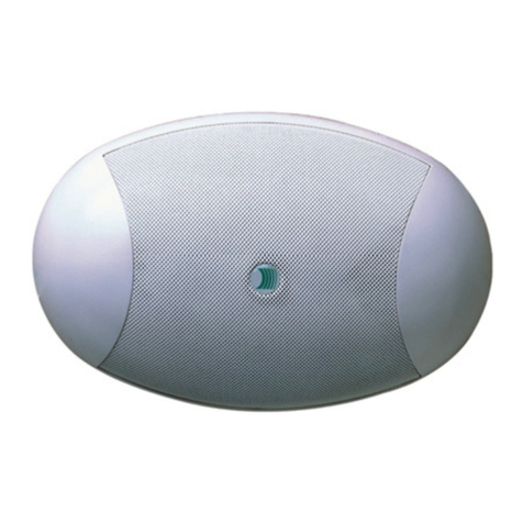
Diffusore ovale da parete e soffitto
Oval speaker unit for wall and ceiling-mounting
Diffuseur ovale mural ou de plafond
OvalerLautsprecherfürdieWand-oderDeckenmontage
Ovale wand/plafondluidspreker
Difusor oval de pared y techo
C36/6-T
SOMMARIO
Note di sicurezza .......................................................................... 1
Installazione e montaggio ............................................................. 2
Connessioni e regolazioni.............................................................. 2
Caratteristiche tecniche................................................................ 4
TABLE OF CONTENTS
Safety notes ................................................................................ 1
Installation and mounting ............................................................. 2
Connections and settings ............................................................. 2
Technical specifications................................................................. 4
SOMMAIRE
Notices de sécurité ....................................................................... 1
Installation et montage................................................................. 2
Connexions et réglages ................................................................ 2
Caractéristiques techniques.......................................................... 4
INHALTSANGABE
Sicherheitshinweise ...................................................................... 1
Installation und Montage .............................................................. 2
Anschlüsse und Einstellungen ....................................................... 2
Technische Eigenschaften............................................................. 4
INHOUD
Veiligheidsvoorschriften ................................................................ 1
Installatie en montage .................................................................. 2
Aansluitingen en afstellingen ........................................................ 2
Technische kenmerken .................................................................. 4
SUMARIO
Notas de seguridad ...................................................................... 1
Instalación y montaje ................................................................... 2
Conexiones y ajustes ................................................................... 2
Características técnicas................................................................ 4
Istruzioni d’installazione e montaggio
Instructions for installation and mounting
Instructions pour l'installation et le montage
Installations- und Montageanweisungen
Instructies voor installatie en montage
Instrucciones de instalación y montaje
NOTE DI SICUREZZA
Leggere attentamente il presente foglio istruzioni. La PASO declina ogni
responsabilità per danni a persone e/o cose derivanti dalla non corretta
installazione e dall'uso improprio del prodotto.
La messa in opera del diffusore deve essere effettuata da personale
addestrato: un'errata installazione potrebbe comportare il rischio di scossa
elettrica.
VEILIGHEIDSVOORSCHRIFTEN
Lees dit instructieblad aandachtig door. PASO aanvaardt geen
aansprakelijkheid voor persoonlijk letsel en/of schade aan voorwerpen
die het gevolg zijn van een niet correcte installatie en een oneigenlijk
gebruik van het product. De luidspreker moet door speciaal opgeleid
personeel in bedrijf worden gesteld: een onjuiste installatie kan gevaar
voor elektrische schokken met zich mee brengen.
NOTAS DE SEGURIDAD
Leer detenidamente este folleto de instrucciones. La PASO rehusa
cualquier responsabilidad ante daños a personas y/o cosas causados
por la instalación no correcta y por el uso no adecuado del producto.
La instalación del difusor debe ser efectuada por personal capacitado:
una instalación errónea puede conllevar el riesgo de sacudidas
eléctricas.
SAFETY NOTES
Please read this instruction sheet carefully. PASO will accept no liability
for personal injury and/or damage to property resulting from incorrect
installation or improper use of the product.
The speaker unit must be set up by trained personnel. Incorrect
installation could result in the risk of electric shocks.
NOTICES DE SECURITE
Lire attentivement le présent feuillet d'instructions. PASO décline toute
responsabilité pour les dommages aux personnes et/ou aux choses dus à
une mauvaise installation ou à une utilisation incorrecte du produit.
La mise en place du diffuseur doit être effectuée par un personnel expert.
Toute erreur d'installation pourrait présenter un risque d'électrocution.
SICHERHEITSHINWEISE
Lesen Sie diese Anweisungen aufmerksam. PASO übernimmt keine Haftung
für Schäden an Personen und/oder Gegenständen, die durch eine nicht
ordnungsgemäße Installation und einen nicht sachgemäßen Gebrauch
des Produkts verursacht werden.
Die Inbetriebnahme des Lautsprechers muss von Fachpersonal
vorgenommen werden: bei falscher Installation besteht die
Stromschlaggefahr.
11-573_A.pmd 14/06/2005, 10.141
2
C36/6-T
INSTALLAZIONE E MONTAGGIO
Il diffusore C36/6-T è dotato di un traslatore per il
collegamento alle linee di distribuzione a 'tensione
costante' a 50, 70 e 100V. L'installazione di questi
diffusori può essere effettuata in tre diverse modalità,
a seconda delle esigenze. Il montaggio a parete
orizzontale (fig. 1), prevede l’utilizzo dei fori [A],
mentre per quello verticale (fig. 2) è necessario
utilizzare i fori [B]. In questi casi il fissaggio può
essere effettuato sia con viti autofilettanti a testa
svasata (Ø 4÷4,5mm) che con tasselli ad espansione
con gancio corto (vedi particolare D). Per il fissaggio
a soffitto (Fig. 3) utilizzare esclusivamente viti
autofilettanti a testa svasata (Ø 4÷4,5mm) da inserire
nei fori [C]: far passare le teste delle viti nella parte
più grande delle asole (1) e spostare il diffusore fino
a portare le teste delle viti in fondo alle asole (2).
CONNESSIONI E REGOLAZIONI
I diffusori C36/6-T devono essere collegati in
derivazione alla linea di distribuzione, assicurandosi
che la potenza complessiva assorbita dai diffusori
non ecceda quella massima fornita dall'amplificatore
(in figura 4 è mostrato un collegamento alla linea
100V). La potenza dei diffusori è impostata in fabbrica
per linea 100V/6W. Nel caso si volesse modificare
questa impostazione, è possibile cambiare la potenza
di uscita tramite l’apposito terminale ad inserzione
rapida facendo riferimento alla targhetta posta sul
trasformatore (vedi fig. 5, pag. 4).
INSTALLATION AND MOUNTING
The C36/6-T speaker has a repeater for connection
to the 50, 70 and 100 V ‘constant-voltage distribution
lines. These speaker units can be mounted in three
different ways, depending on requirements.
They can be mounted on horizontal walls (Fig, 1)
by means of the holes [A], or on vertical walls (Fig.
2) using the holes [B]. In these cases, they can be
fixed into place either by means of self-tapping
countersunk screws (Ø 4 to 4,5 mm) or with anchor
bolts with short hooks (see close-up D).
For ceiling mounting (Fig. 3) use only self-tapping
countersunk screws (Ø 4 to 4,5 mm) to be inserted
into the holes [C]: insert the head of each screw
into the wider part of its slot (1), then move the
speaker unit until the heads of the screws are at the
bottom of their slots (2).
CONNECTIONS AND SETTINGS
C36/6-T speaker units must be shunted to the
distribution line, making sure that the maximum
power absorbed overall by the units does not exceed
the maximum output power supplied by the amplifier
(Figure 4 shows a connection to the 100 V line). The
output power of the speaker units is factory set for
a 100 V / 6 W line. If changing this setting is required,
it is possible to change the output power by means
of the plug-in terminal provided, referring to the
label on the transformer (see Fig. 5, page 4).
INSTALLATION ET MONTAGE
Le diffuseur C36/6-T est équipé d'un translateur
pour la connexion aux lignes de distribution à 'tension
constante' à 50, 70 et 100V. Selon les exigences,
l'installation de ces diffuseurs peut avoir lieu de trois
façons différentes. Le montage sur un mur horizontal
(fig. 1) prévoit l'utilisation des trous [A] alors que
sur un mur vertical (fig. 2) il faut utiliser les trous
[B]. Dans les deux cas, la fixation peut avoir lieu à
l'aide de vis autotaraudeuses à tête fraisée (Ø 4÷4,5
mm) ou de chevilles expansibles à crochet court
(voir détail D). Pour la fixation au plafond (fig. 3),
utiliser uniquement des vis autotaraudeuses à tête
fraisée (Ø 4÷4,5 mm) qui doivent être introduites
dans les trous [C]: faire passer les têtes des vis dans
la partie large des boutonnières (1), puis déplacer le
diffuseur jusqu'à ce que les têtes des vis se retrouvent
au fond des boutonnières (2).
CONNEXIONS ET REGLAGES
Les diffuseurs C36/6-T doivent être connectés en
dérivation par rapport à la ligne de distribution, en
s'assurant que la puissance totale absorbée par les
diffuseurs ne dépasse pas la puissance maximum
fournie par l'amplificateur (la figure 4 reporte un
exemple de connexion à la ligne 100V). La puissance
des diffuseurs est établie en usine pour une ligne
100V/6W. Pour modifier cette configuration, changer
la puissance de sortie à l'aide de la borne à connexion
rapide ad hoc en se référant à la plaque située sur le
transformateur (voir fig. 5, page 4).
INSTALLATION UND MONTAGE
Der Lautsprecher C36/6-T besitzt einen Überträger
für den Anschluss an Verteilungsleitungen mit
Gleichspannung von 50, 70 und 100V. Die Installation
dieser Lautsprecher kann, je nach Anforderung,
auf drei verschiedene Weisen erfolgen. Bei der
Montage an Decken (Abb. 1) ist die Verwendung
der Öffnungen [A] vorgesehen während bei der
Montage an Wänden (Abb. 2) die Öffnungen [B]
verwendet werden. In diesen Fällen kann die
Befestigung sowohl mit selbstwindenden
Senkschrauben (Ø 4÷4,5 mm) als auch mit Dübeln
mit kurzem Haken (s. Detailzeichnung D) erfolgen.
Für die Deckenbefestigung (Abb. 3) dürfen nur
selbstwindende Senkkopfschrauben (Ø 4÷4,5 mm)
verwendet werden, die in die Öffnungen [C]
eingesetzt werden: Setzen Sie die Schraubenköpfe
in den weiteren Teil der Öffnungen ein (1) und
schieben Sie den Lautsprecher, bis die
Schraubenköpfe auf dem Grund der Öffnungen
positioniert sind (2).
ANSCHLÜSSE UND EINSTELLUNGEN
Die Lautsprecher C36/6-T müssen als Abzweigung
von der Verteilerleitung angeschlossen werden. Stellen
Sie sicher, dass die insgesamt von den Lautsprechern
aufgenommene Leistung nicht die maximale vom
Verstärker abgegebene Leistung übersteigt (in der
Abbildung 4 ist der Anschluss an eine 100V-Leitung
dargestellt). Die Leistung der Lautsprecher ist werkseitig
für eine 100V/6W-Leitung eingestellt. Falls diese
Einstellung geändert werden soll, besteht die
Möglichkeit, die Ausgangsleistung mit Hilfe des
entsprechenden Endstücks mit Schnellverschluss zu
verstellen. Hierbei muss das Typenschild auf dem
Transformator (s. Abb. 5, Seite. 4) beachtet werden.
INSTALLATIE EN MONTAGE
De luidspreker C36/6-T is voorzien van een
transformator voor de aansluiting op de
distributielijnen 'constante spanning' van 50, 70 en
100V. Deze luidsprekers kunnen op drie verschillende
manieren geïnstalleerd worden, al naargelang uw
persoonlijke vereisten. Bij horizontale montage aan
de wand (afb. 1) worden de gaten [A] gebruikt,
terwijl voor de montage in verticale stand (afb. 2)
de gaten [B] gebruikt moeten worden. In deze
gevallen kan de bevestiging zowel met zelfborgende
schroeven met verzonken kop (Ø 4÷4,5mm) als
met expansiepluggen met korte haak (zie detail D)
worden uitgevoerd. Voor de bevestiging aan het
plafond (Afb. 3) gebruikt u uitsluitend zelfborgende
schroeven met verzonken kop (Ø 4÷4,5mm) die in
de gaten [C] worden gestoken: steek de kop van
de schroeven door het breedste gedeelte van de
sleuven (1) en verplaats daarna de luidspreker tot
de koppen van de schroeven zich onderaan de
sleuven bevinden (2).
AANSLUITINGEN EN AFSTELLINGEN
De luidsprekers C36/6-T moeten als vertakking
van de distributielijn worden aangesloten en men
dient zich ervan te verzekeren dat het totale door
de luidsprekers opgenomen vermogen niet groter
is dan het maximumvermogen dat de versterker
kan leveren (op afbeelding 4 wordt een aansluiting
op de 100V lijn getoond). Het vermogen van de
luidsprekers wordt in de fabriek ingesteld voor
een 100V/6W lijn. Indien u deze instelling wilt
wijzigen, is het mogelijk het uitgangsvermogen te
veranderen middels de hiertoe bestemde klem met
snelaansluiting, aan de hand van het plaatje op de
transformator (zie afb. 5, pag. 4)
INSTALACIÓN Y MONTAJE
El difusor C36/6-T tiene un translador para la
conexión a las líneas de distribución de 'tensión
constante' de 50, 70 y 100V. La instalación de estos
difusores se puede efectuar de tres distintas maneras,
según las exigencias. El montaje mural horizontal
(fig. 1), prevé el uso de los agujeros [A], mientras
que para el montaje vertical (fig. 2) es necesario
utilizar los agujeros [B]. En estos casos la fijación se
puede efectuar tanto con tornillos de rosca golosa
con cabeza avellanada (Ø 4÷4,5mm) como con
pernos de expansión con gancho corto (ver detalle
D). Para la fijación en techo (Fig. 3) utilizar
exclusivamente tornillos de rosca golosa de cabeza
avellanada (Ø 4÷4,5mm) a introducir en los agujeros
[C]: hacer pasar las cabezas de los tornillos en la
parte más grande de las ranuras (1) y seguidamente
desplazar el difusor hasta llevar las cabezas de los
tornillos al fondo de las ranuras (2).
CONEXIONES Y AJUSTES
Los difusores C36/6-T se deben conectar en
derivación a la línea de distribución, comprobando
que la potencia total absorbida por los difusores no
supere la máxima proporcionada por el amplificador
(en la figura 4 se muestra una conexión a la línea
100V). La potencia de los difusores está programada
en fábrica para línea de 100V/6W.
Si se desea modificar esta configuración, es posible
cambiar la potencia de salida mediante el terminal
previsto de conexión rápida, haciendo referencia a
la placa situada en el transformador (véase fig. 5,
pág. 4).
Fig. 3Fig. 2Fig. 1
132 mm
116 mm
147 mm
D
1
2
11-573_A.pmd 14/06/2005, 10.142
3
DIMADIFORATURA-DRILLINGTEMPLATE
258 mm
169 mm
11-573_A.pmd 14/06/2005, 10.143
4
C36/6-T
CARATTERISTICHE TECNICHE TECHNICAL SPECIFICATIONS
T-6/63C
elanimonaznetoP rewoptuptuodetaR elanimonecnassiuP gnutsielnneN lanimonaicnetoP negomrevlaanimoN W6
e
libalogeraznetoP rewoptuptuoelbatsujdA elbalgérecnassiuP gnutsieLerablletsniE elbalugeraicnetoP negomrevra
ablegeR W5.1,W3,W6
azneuqerfniatsopsiR esnopserycneuqerF ecneuqerfneesnopeR gnagzneuqerF aicneucerfneatseup
seR snopsereitneuqerF zH00001÷051
aznedepmI ecnadepmI ecnadépmI znadepmI aicnadepmI eitnadepmI 5.gifidev
azneic
iffE ycneiciffE éticaciffÉ gnutsieL eitneiciffE aicneicifE Bd88 )m1/W1(
enoisrepsididolognA elgnanoisrepsiD noi
srepsidedelgnA lekniwsgnulhartssuA nóisrepsidedolugnA keoheisrepsiD °051 )zHk2@(
inoisnemiD snoisnemiD snoisn
emiD negnussembA sadideM negnitemfA mm27x961x852
oseP thgieW sdioP thciweG oseP thciweG gk57,0
Fig. 4
Frequency (Hz)
Magnitude (dB)
Piano orizzontale - Horizontal planRisposta in frequenza - Frequency response
NOTA
La PASO declina ogni responsabilità per danni a cose e/o persone derivanti
dall'uso non corretto dell'apparecchio o da procedure non rispondenti a quanto
riportato sul presente libretto. Nel continuo intento di migliorare i propri prodotti,
la PASO S.p.A. si riserva il diritto di apportare modifiche ai disegni e alle
caratteristiche tecniche in qualsiasi momento e senza alcun preavviso.
Via Mecenate, 90 - 20138 MILANO - ITALIA
TEL. +39-02-580 77 1 (15 linee r.a.)
FAX+39-02-58077277
http://www.paso.it
Printed in Italy - 06/05 - 1K - 11/573-A
NOTES
PASO will not accept any liability for damage to property and/or persons arising
out of incorrect use of the equipment or of procedures that do not comply with
the instructions provided in this booklet. PASO S.p.A. strive to improve their
products continuously, and therefore reserve the right to make changes to the
drawings and technical specifications at any time and without notice.
S.p.A
Fig. 4 Fig. 5
11-573_A.pmd 14/06/2005, 10.144

Other Paso Speakers manuals

Paso C36/6-EN User manual

Paso

Paso C36/6-EN User manual

Paso C572/6-V User manual

Paso

Paso C572/6-V User manual

Paso PMS2000 Series User manual

Paso

Paso PMS2000 Series User manual

Paso C45/12V-EN User manual

Paso

Paso C45/12V-EN User manual

Paso C93 Series Service manual

Paso

Paso C93 Series Service manual

Paso C400 Series User manual

Paso

Paso C400 Series User manual

Paso TA16-F User manual

Paso

Paso TA16-F User manual

Paso C47/6-TB Service manual

Paso

Paso C47/6-TB Service manual

Paso TR10-TW User manual

Paso

Paso TR10-TW User manual

Paso C53/10-T User manual

Paso

Paso C53/10-T User manual

Paso C37/6-EN User manual

Paso

Paso C37/6-EN User manual

Paso C57-T Service manual

Paso

Paso C57-T Service manual

Paso C33/10-T User manual

Paso

Paso C33/10-T User manual

Paso C980 User manual

Paso

Paso C980 User manual

Paso C44/12-EN User manual

Paso

Paso C44/12-EN User manual

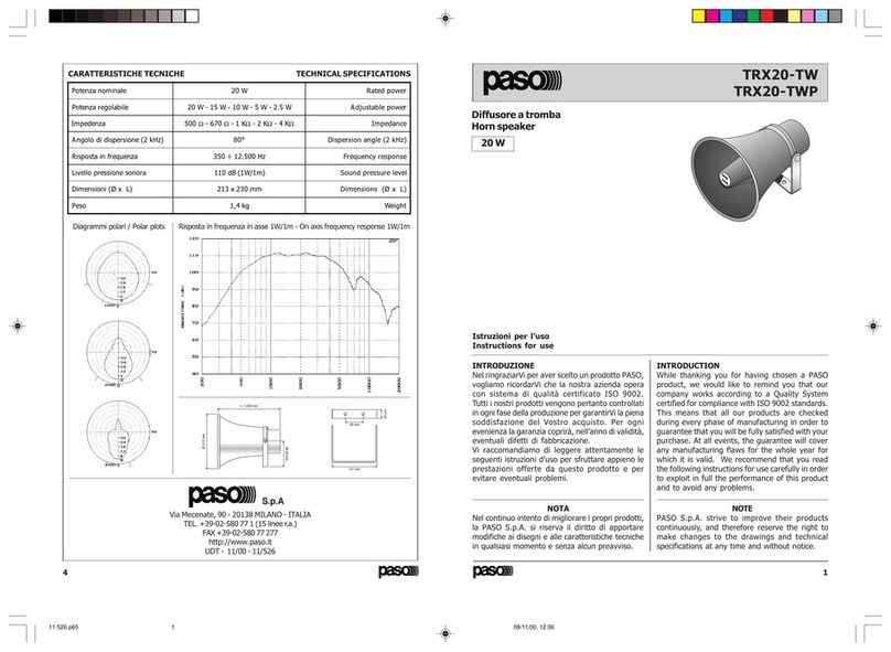
Paso TRX20-TW User manual

Paso

Paso TRX20-TW User manual

Paso C96-EN Series User manual

Paso

Paso C96-EN Series User manual

Paso C420-T User manual

Paso

Paso C420-T User manual

Paso C7200-EN User manual

Paso

Paso C7200-EN User manual

Paso C44/6-TB Service manual

Paso

Paso C44/6-TB Service manual

Paso TR1-B User manual

Paso

Paso TR1-B User manual

Paso C36/6 User manual

Paso

Paso C36/6 User manual

Paso C44/6-T Service manual

Paso

Paso C44/6-T Service manual

Paso C150-HF Guide

Paso

Paso C150-HF Guide

Popular Speakers manuals by other brands

Gembird ACT-SPK-BT-03 user manual

Gembird

Gembird ACT-SPK-BT-03 user manual

Boston Acoustics S95 user manual

Boston Acoustics

Boston Acoustics S95 user manual

Bowers & Wilkins DM 605 S2 Specification sheet

Bowers & Wilkins

Bowers & Wilkins DM 605 S2 Specification sheet

Bose SoundLink Mini Bluetooth speaker II owner's guide

Bose

Bose SoundLink Mini Bluetooth speaker II owner's guide

Community iBOX M12 Operation and installation manual

Community

Community iBOX M12 Operation and installation manual

Laney NX115 operating instructions

Laney

Laney NX115 operating instructions

Novik Neo EVOD Bravery 215 instruction manual

Novik Neo

Novik Neo EVOD Bravery 215 instruction manual

Philips HTL2163B user manual

Philips

Philips HTL2163B user manual

Memphis M Series quick start guide

Memphis

Memphis M Series quick start guide

Pinnacle PR MAN TRICHANNEL REV0210 manual 

Pinnacle

Pinnacle PR MAN TRICHANNEL REV0210 manual 

Fender SPL 1225 owner's manual

Fender

Fender SPL 1225 owner's manual

rough country Premium 10 manual

rough country

rough country Premium 10 manual

Lyngdorf LS-1000 installation manual

Lyngdorf

Lyngdorf LS-1000 installation manual

Mackie FreePlay HOME owner's manual

Mackie

Mackie FreePlay HOME owner's manual

Extron electronics FF 220T user guide

Extron electronics

Extron electronics FF 220T user guide

BEATFOXX Outdoorjam OJ-18 instruction manual

BEATFOXX

BEATFOXX Outdoorjam OJ-18 instruction manual

SANYUN SW-208 quick start guide

SANYUN

SANYUN SW-208 quick start guide

Gogen BPS 898 user manual

Gogen

Gogen BPS 898 user manual

manuals.online logo
manuals.online logoBrands
  • About & Mission
  • Contact us
  • Privacy Policy
  • Terms and Conditions

Copyright 2025 Manuals.Online. All Rights Reserved.