Patchwork Technology BlackBox air User manual

User Guide

2
Mount to the windscreen using supplied suction mount and arm.
Warranty Void if suction mount fails !! - It is advised that the suction mount is
removed from the windscreen when the unit is not in operation and reattached on a
day to day basis.
For a more permanent xing, a mounting kit that can be secured to the vehicle is available
for an additional cost.
Touch Screen
On/O button
Mini USB
Charge port
Display

3
Installing the Unit
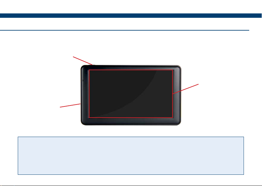
If the tilt function is required, the unit needs to be securely mounted on a at surface with
the ‘Y’ pointing towards the direction of travel.
12v DC Plug
Plug into 3 pin socket on vehicle.
USB Power Socket
Charge the screen via supplied USB Cable.
It is recommended that the charge cable
is always connected to the screen whilst
in use.
Magnetic Antenna
Install centrally across the width of the
roof (if the roof is not metal use the
roof mount plate supplied).
Important!! Completely uncoil the
cable and route around the cab.
Warning - Please
disconnect the unit
from the power supply,
if you need to jump
start your vehicle.
GPS Receiver and Tilt unit

4
To access the
setup screens
press Setup
on the Home
screen.
To return to the
Home screen
press the Home
button.
Guidance Setup
Set the working
width for guidance
and coverage. Set the coverage
recording On/O
method (see over).
To oset the
antenna position
if not central or
when using an
oset mower.
To congure
the built in tilt
correction.
The following overview highlights where to nd the common settings for guidance and
area measurement.

5
Setup
Coverage Recording On/O Method
On Screen - Coverage recording can be turned on and o manually via the Recording
On/O button (see Guidance Screen Overview).
Always Record - Coverage recording continually records and cannot be turned o.
Auto Record - Air+ software feature (see Air+ Features > Auto Record for details).
Enable Tilt Correction (If required)
1) Press Tilt Compensator 2) Set Tilt to ‘On’, enter
Height, distance from the
ground to the antenna.
3) Position the vehicle on a
known level surface, press
Zero Tilt.

6
Local Setup
To access the
local setup
screen, press
Unit Setup.
Next select Local
Setup.
Select the country
of use.
Select the display
language.
Set the units of
measurement for
the display.

7
Hardware Setup
To access the
hardware setup
screen, press the
Hardware Setup
icon.
Press and hold
on the white dot
then slide nger to
adjust the screen
brightness, release
nger to set*.
Press and hold
on the white dot
then slide nger to
adjust the screen
volume, release
nger to set*.
Setup
*Alternatively press directly on the bar to adjust.

8
Important! Before starting a job ensure the correct Bluetooth device is connected and that
the GPS Quality level is within the green. This ensures the best GPS performance for use
with guidance and area measurement.
1) Press Start Job. 2) Enter the Farm/Field
name and Conrm.
3) Check working Width,
select Guidance Mode and
press Conrm to begin job.
Start Job
Use this method for starting a job, to save Boundary Maps, use Field Recognition and the
following Air+ features:- Pause/Resume job, Boundary Printing and Coverage Job Data
Sync.

9
Starting a Job
Guidance Modes
Straight - Sets a straight guidance line between set point A and point B, which is then replicated
both sides of the original line at equal intervals based on the entered width.
Curved - Creates a curved guidance line based on the path driven between set point A and
point B. The line is then replicated both sides of the original line at equal intervals based on the
entered width.
1) Press Quick Job. 2) Launches the Guidance
screen, ready for work.
Quick Job
Use this method to start a job, when a job or multiple jobs do not require boundary maps
to be saved or job recording.

10
If a Farm or Field name has been entered incorrectly or is no longer required it can be
easily renamed or deleted from the system using the job maintenance tools.
List Bar
Renaming/Deleting a Farm or Field
Previous Scroll Up Scroll Down Delete Edit Conrm
1) Select Start Job > Farm. 2) Highlight the Farm
name and go to step 3) to
adjust the farm.
Or press Conrm and go
to step 4) to adjust the
eld.

11
Job Maintenance
Or press the Delete Button
to remove the Farm and all
its Fields.
Or press the Delete button
to remove eld.
4) Highlight the Field
name.
3) Press the Edit button
to rename, enter the new
name and press OK.
5) Press the Edit button
to rename, enter the new
name and press OK.
Warning!! Deleting a farm or eld will permanently remove all boundary and coverage
map data associated with it.

12
Guidance Screen Overview
Information Panel
Guidance Status
Start/Pause
Boundary
Close
Boundary
Guidance
Options
Recording
On/O Menu
Recalibrate
Guidance Line
(Straight Mode
Only)
Mini Map (Toggle
2D mode)
Working Width
Distance Travelled
Ground speed (Toggle Speedometer /Digital)
GPS Strength
Coverage Area

13
Measuring Field Area
Important! Do not start a boundary recording from the corner of a eld.
1) After starting a new job, position your vehicle along
the edge of the eld at least 30 metres from a corner
and press Start/Pause Boundary.
2) Set Boundary Type to Boundary.
3) Set the Oset to the distance from the antenna to the
edge of the eld.
4) Press Start and drive around the eld back to the start point. The BlackBox will
automatically close and save the boundary map, then display the eld shape and size in the
mini map. If the boundary doesn’t close, press the Close Boundary button.
N.B. During the boundary run the boundary recording can be paused and restarted using
the Start/Pause Boundary button, if there is a need to drive around obstacles.
To do a new boundary map redo steps 1) to 4).
Tip! Field Boundary Maps are saved to the system using the Farm/Field name entered
when ‘Starting a Job’ and the next time the eld is entered the system will Automatically
Detect the eld, displaying its name on the Home screen.

14
2) At the beginning of a straight run
press the Grid area to set point A.
3) Drive to the end of the run and press
the Grid area to set B. The guidance
line will appear ready for guidance.
N.B. The green coverage recording can be turned on and o using the ‘Recording On/O’
button if ‘On Screen’ has been set.
1) Position the vehicle in the eld where the job will begin. (When using a curved line it is
important to use the longer edge of the eld to set a guide line).
Grid
area
N.B. When following a guidance line gently drift into position when lining up, then once
aligned look up and aim for a feature, looking at the screen from time to time to ensure
you are still on line.

15
Setting and Using a Guidance Line
4) Turn onto the next run then line up
the red arrow to the guidance line and
follow it along the run.
5) Once the run is complete turn onto
the next run and the next AB line will
appear to line up to.
To complete a eld boundary map or guidance job to start a new one, press the Menu
button and then Next Job to start a new job with the same settings or Finished Job to
return to the Home screen.
To power o the BlackBox press Shutdown > Yes and disconnect from power supply.
Tip! Pressing the Grid area a third time allows the guidance line to be reset and if using
the ‘Straight’ guidance mode, recalibrated to realign with current location.
Finishing a Job

16
Pause Job
The following setup instructions are exclusive to Air+ software users, the
Air+ software is a paid for upgrade which is available to all BlackBox Air
users and includes the following features :- Pause Job | Auto Record |
Headland Guidance | Headland Warning | Job Data Sync and Tracking |
Boundary Printing
Resuming a Paused job
To continue a Paused job, press Start Job and an option box will appear with the option
to continue the paused job. Pressing Yes will resume the job with a red marker in the mini
map to show where the job was paused.
1) When in the Job screen, Press
Menu.
2) Press Pause Job, this will save the
coverage area and any guidance lines
that are set.

17
Air+ Features
Auto Record
Auto record automatically turns the coverage recording OFF when 75 percent of the working
width goes inside a previously recorded area and turns back ON when 25 percent of the
working width is outside the recorded area.
1) On the Home screen, press Setup.
3) Select On/O, choose Auto
Record from the list and press OK.
2) Then press Guidance Setup.
4) Press Home, Auto Record is set
ready to begin a job.

18
Headland Guidance
Headland guidance uses an existing Field Boundary Map (see Measuring Field Area) to create
a guidance line based on the working width. This guidance line is to guide the user when
working the headland of the eld.
1) When in the job screen with the
Field Boundary loaded, press in the
area as shown above.
3) To switch back to AB guidance
press on ‘H:’.
2) The headland guidance line will
appear indicated by ‘H:’, ready to
guide.
Tip! Alternatively Headland Guidance
can be activated in Guidance Options
by selecting Headland and deactivated
by selecting Track.

19
Air+ Features
Headland warning creates a headland zone from the Field Boundary Map at a distance
specied by the user as the ‘Headland Size’. As the user approaches the edge of the zone a
distance counter will countdown to zero alerting the user to stop or start the implement.
1) On the home screen, press
Setup > Guidance Setup.
2) Press Antenna Oset, then
tick and select A
3) Enter the distance from the antenna
to the working part of the implement.
4) Press Home, then Setup > Air+
Setup > Headland Warning Setup.
Headland Warning

20
7) Headland Delay On / Headland
Delay O, these can be set to alert the
user earlier, i.e. if 2 seconds is entered
the user will be alerted 2 seconds
before the edge of the zone.
8) Press Home, Headland
Warning is now setup ready to
begin a job.
5) Press Headland Warning
and select Enable.
6) Press Headland Size and
enter the distance required.
Table of contents
Other Patchwork Technology Marine Equipment manuals
Popular Marine Equipment manuals by other brands

Standard Communications
Standard Communications Horizon WS45 owner's manual

Argus Security
Argus Security VEGA FLEXIPLUS VC-BS-01 manual

IMAGENEX
IMAGENEX 853 manual

Furuno
Furuno FCV-585 Operator's manual

Taco Marine
Taco Marine Neptune III Installation instruction guide

GENASYS
GENASYS LRAD 450XL Equipment manual