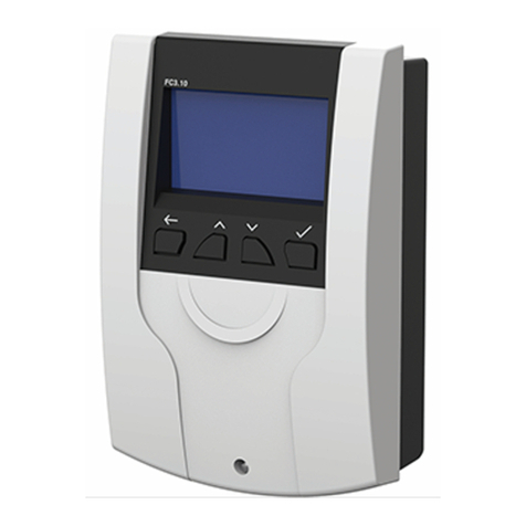
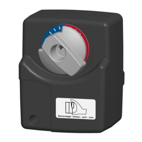
PAW FC3.10 User manual

PAW GmbH & Co.KG
Böcklerstr. 11, D-31789 Hameln
Phone: +49 (0)5151-9856-0, Fax: +49 (0)5151-9856-98
E-mail: info@paw.eu, Web: www.paw.eu
2019/09 99E13331xx-mub-en - V02 1
Installation and Operation Instructions
Controller FC3.10
for DHW modules

1General Information
2 99E13331xx-mub-en - V02 2019/09
Item no. 99E13331xx-mub-en - Version V02 - Issued 2019/09
Translation of the original instructions
We reserve the right to make technical changes without notice!
Printed in Germany – Copyright by PAW GmbH & Co. KG
PAW GmbH & Co.KG
Böcklerstraße 11
D - 31789 Hameln, Germany

1General Information
2019/09 99E13331xx-mub-en - V02 3
Contents
Contents ................................................................................................................................3
1General Information.........................................................................................................5
1.1 Scope of these instructions ..........................................................................................5
1.2 Designated use ............................................................................................................ 5
1.3 EC Declaration of Conformity .......................................................................................5
1.4 Target group ................................................................................................................ 5
2Safety instructions ...........................................................................................................6
3Assembly and installation [specialist]................................................................................7
3.1 Assembly of the controller ............................................................................................ 7
3.2 Establishing the electrical connections ......................................................................... 9
4Commissioning [specialist].............................................................................................11
5Product description........................................................................................................12
5.1 Screen........................................................................................................................12
6Operation ......................................................................................................................13
6.1 Block diagram ............................................................................................................ 13
6.2 Status.........................................................................................................................14
6.3 Hot water (HW) .......................................................................................................... 14
6.3.1 Domestic hot water nominal temperature ............................................................ 14
6.3.2 Comfort function..................................................................................................14
6.3.3 Dynamic domestic hot water control.................................................................... 15
6.3.4 Blocking protection.............................................................................................. 16
6.4 Functions ................................................................................................................... 16
6.4.1 Circulation ........................................................................................................... 16
6.4.2 Stratification ........................................................................................................20
6.4.3 Thermal disinfection ............................................................................................22
6.4.4 Alarm relay..........................................................................................................24
6.4.5 Parallel relay ....................................................................................................... 25
6.4.6 Hygienic flush......................................................................................................25
6.5 Checking the temperature of the buffer tank............................................................... 25
6.6 Back-up heating ......................................................................................................... 26

1General Information
4 99E13331xx-mub-en - V02 2019/09
6.7 Basic settings............................................................................................................. 26
6.7.1 Language ............................................................................................................ 26
6.7.2 Automatic DST ....................................................................................................26
6.7.3 Date ....................................................................................................................26
6.7.4 Time.................................................................................................................... 27
6.7.5 Display ................................................................................................................27
6.7.6 Updating the firmware .........................................................................................27
6.7.7 Information ..........................................................................................................27
6.8 USB ........................................................................................................................... 27
6.9 Manual operation ....................................................................................................... 28
6.10 User code................................................................................................................... 28
7Technical data...............................................................................................................29
8Error messages / Error correction...................................................................................31
8.1 General error correction ............................................................................................. 31
8.2 Checking flow sensor VFS 2-40 ................................................................................. 33
Only for FriwaMini ............................................................................................................. 33
8.3 Checking flow sensor FlowSonic ................................................................................ 34
8.3.1 Only for FriwaMidi, FriwaMaxi, FriwaMega:......................................................... 34
9Exclusion of liability .......................................................................................................36
10 Legal guarantee ............................................................................................................37

1General Information
2019/09 99E13331xx-mub-en - V02 5
1General Information
1.1 Scope of these instructions
These instructions describe the function, installation and commissioning of the DHW controller
FC3.10. The chapters called [specialist] are intended for specialists only.
For other components of the heating system, such as valves, please follow the instructions of
the respective manufacturer.
1.2 Designated use
The domestic hot water controller, subsequently referred to as the controller, is an
independently installed electronic temperature controller for on-surface installation.
The integration into a pump assembly is possible when the technical specifications of the
controller are adhered to. The maintenance-free controller is exclusively intended for the
controlling and monitoring of a PAW domestic hot water module. Only use PAW accessories
with the controller.
1.3 EC Declaration of Conformity
This product conforms to the applicable European directives with regard to its design and its
operating behaviour. This conformity has been verified.
Further information in this regard can be obtained from your dealer.
1.4 Target group
The target audience of this manual are technical professionals who:
•Have the knowledge of terminology and the skills necessary for setting up and
operating domestic hot water stations.
•Have the necessary professional training, knowledge and experience as well
as the knowledge of the relevant regulations, in order to evaluate the following
work and to detect potential dangers:
– Installation of electrical devices
– Assembly and connection of data lines
– Assembly and connection of power supply lines
Carefully read these instructions before installation and commissioning.
Save these instructions in the vicinity of the installation for future reference.

2Safety instructions
6 99E13331xx-mub-en - V02 2019/09
2Safety instructions
The installation and commissioning as well as the connection of electrical components require
technical knowledge commensurate with a recognised vocational qualification as a fitter for
plumbing, heating and air conditioning technology, or a profession requiring a comparable level
of knowledge [specialist].
The following must be observed during installation and commissioning:
•relevant local and national regulations
•accident prevention regulations of the professional association
•instructions and safety instructions of this manual
This document is part of the product.
Install and use the device only after having read and understood this document. Please observe
all safety instructions. Please contact an additional expert if uncertainties occur.
The measures described in this document may only be carried out by qualified technical
professionals. Exception: End customers are allowed to operate the controller if they have been
trained by a technical professional beforehand.
The domestic hot water module can be damaged by improper operation of the device.
The device must not be connected to the power supply if:
-the housing is open or damaged
-cables are damaged
Factory labels and markings must never be modified, removed or rendered unreadable.
Observe the prescribed operating conditions. For more information, see the section
Technical data
.
This device is not intended for:
-Children
-Persons with restricted physical, sensory or mental capacities
-Persons without sufficient experience or knowledge
unless they are instructed in the use of the device, and initially supervised,
by a person responsible for their safety

3Assembly and installation [specialist]
2019/09 99E13331xx-mub-en - V02 7
3Assembly and installation [specialist]
3.1 Assembly of the controller
NOTICE
The following section describes only the installation of the controller. Follow the instructions
of each respective manufacturer when installing external components (valves etc.).
1. Temperature sensors
2. Flow sensors
3. Outputs PWM
4. Modbus
5. RS232
6. Outputs 230 V
7. Supply
WARNING
Risk of death by electrocution!
Disconnect the controller from the power supply before opening the
casing.
Make sure that the power supply cannot be unintentionally switched on
when the casing is open.

3Assembly and installation [specialist]
8 99E13331xx-mub-en - V02 2019/09
Input:
Terminal Individual operation mode / Cascade operation mode
S1, ꞱFlow temperature, primary (T-FL)
S2, ꞱDomestic hot water temperature, secondary T)
S3, ꞱOptional: Sensor for storage tank temperature (T-SP)
S4, ꞱCold water temperature, secondary (T-CW)
VFS/US1 VSF-/Ultrasonic sensor
Outputs:
Terminal Individual operation mode Cascade operation mode
R1 --- Cascade valve
R2 Return stratification (optional) Return stratification
(optional, at master controller
R3 Primary / Secondary pump Primary / Secondary pump
PWM 1 Primary pump Primary pump
PWM 2 Secondary pump (circulation) Secondary pump
(circulation, at master controller)

3Assembly and installation [specialist]
2019/09 99E13331xx-mub-en - V02 9
3.2 Establishing the electrical connections
WARNING
Risk to life and limb due to electric shock!
Make sure that the following conditions are satisfied when performing the work
described in this section:
All cables leading to the controller must be disconnected from the power
supply and it must be ensured that they cannot be unintentionally
reconnected during installation.
The protective earth conductors (PE) from the mains cable and pump and
valve cables must be connected to the protective earth conductor terminal
block.
All cables must be laid so that persons cannot stand on them or trip over
them.
The cables must satisfy the requirements listed in the Technical data
section.
The local power supply must match the specifications on the type plate of
the controller.
The power supply cable is to be connected to the mains power as follows:
-using a plug connected to a wall mains socket or
-via an isolating mechanism allowing complete isolation in the case of
permanent wiring.
The power supply cable must be laid in conformance to all applicable legal
guidelines and regulations of the local electricity supplier.
ATTENTION
Danger of damage and malfunction!
Connect only components that do not overload the controller inputs and outputs;
more information is provided on the type plate and in the
Technical data section
.

3Assembly and installation [specialist]
10 99E13331xx-mub-en - V02 2019/09
NOTICE
Any connection polarity may be used for the 1 – 4 signal inputs and outputs.
Only type Pt1000 temperature sensors may be used.
Lay the sensor cables at least 100 mm away from any power supply cables.
Use shielded sensor cables when inductive sources are present, e.g. high-voltage lines,
radio transmitters, microwave devices.
ATTENTION
Danger of damage and malfunction!
When using a circulation pump, especially with the FriwaMega, the power consumption of the
pumps connected to the controller must absolutely be observed and it has to be checked
whether they are compatible with the controller. In some cases the circulation pump directly
has to be supplied by the mains connection. The speed is controlled via the PWM signal.

4Commissioning [specialist]
2019/09 99E13331xx-mub-en - V02 11
4Commissioning [specialist]
DANGER
Risk to life and limb due to electric shock!
Be sure to perform all the measures listed in the Installation section before
starting the first commissioning.
If the controller is connected for the first time, the message "Please carry out the first start-up" is
displayed on the screen.
After the confirmation, a range of parameters are displayed. The parameters need to be
adjusted in order for the controller to run properly. To confirm the settings, select the
menu item "Save".
NOTICE
If an external storage (USB flash drive) is connected to the USB port, the protocol of the first
commissioning will be stored on it.

5Product description
12 99E13331xx-mub-en - V02 2019/09
5Product description
5.1 Screen
Symbol
Description
Pump
Three-way valve with flow direction
Water withdrawal point
Temperature sensor
Flow sensor
Current operation mode
Navigation keys
Heat exchanger
Button -
Confirm
Storage tank
Button -
Back

6Operation
2019/09 99E13331xx-mub-en - V02 13
6Operation
6.1 Block diagram

6Operation
14 99E13331xx-mub-en - V02 2019/09
6.2 Status
The menu item makes it possible to look through all the active functions, temperatures at the
sensors, relay states, operating times of the devices and alarm history/messages.
6.3 Hot water (HW)
6.3.1 Domestic hot water nominal temperature
This menu item makes it possible to regulate the domestic hot water temperature to the value
that has been set. The temperature of the domestic hot water can be changed within the
following range:
Min.: 35 °C
Max.: 75 °C
Factory default setting: 60 °C
6.3.2 Comfort function
NOTICE
The protection against limescale is deactivated when the heat exchanger is always warm.
Do not activate the comfort function when there is an increased risk of limescale.
The primary inlet to the heat exchanger can be warmed up in order to speed up the start of the
module. To do that, the primary pump is actuated depending on the flow temperature.
The comfort function controls the operation of the primary pump when there is no withdrawal
and circulation. After starting the pump, the comfort function is locked for a waiting time
(time-ComfBreak).
It is possible to limit the waiting time to a specific time window using a weekly timer
(timer same as for circulation). The flow sensor serves as the primary sensor T-FL (S1).
The function can be activated or deactivated (default setting = OFF).
Comfort break, min = 1 min
Comfort break, max = 60 min
Default setting = 10 min

6Operation
2019/09 99E13331xx-mub-en - V02 15
The nominal temperature for the comfort function (T-Comf.ON) can not be set freely,
but is calculated dynamically.
T-Comf.ON, min = 1 K
T-Comf.ON, max = 10 K
T-Comf.ON = dynamic = T-HW-Soll - T-Comf.ON
Default setting = 7 K
Due to the comfort nominal temperature (T-FL, S1) depending on the current hot water
temperature (T-HW-Soll, VFS) a conflict in the function "Dynamic T-HW control" is averted.
Security query:
In order to avoid a permanent operation of the primary pump because of a storage tank that is
not hot enough, the following function disables the pump in such cases:
If within 100 s after the start of the comfort function the flow temperature has not reached the
calculated comfort nominal temperature, the comfort function is blocked for one hour.
The settings of the time control and the individual weekly actuation time comply with the settings
of the circulation function.
6.3.3 Dynamic domestic hot water control
Adjusts the nominal temperature of the domestic hot water to the temperature level of the buffer
tank for preheating systems obtaining their energy from buffer tanks without back-up heating or
for the improvement of the efficiency of systems with unstable temperatures
(T-HW-set = T-FL - -5 K).
The function can be activated or deactivated (default setting = OFF).
Delta T dynamic, min., = 1 K
Delta T dynamic, max., = 20 K
Default setting = 3 K
If the function circulation is selected, the adjustment of the nominal temperature of the domestic
hot water to the temperature level of the buffer tank is blocked.
NOTICE
In cascade operation mode this function is only recommended in exceptional cases,
because high temperature fluctuations at the withdrawal point can occur when switching
between the modules.

6Operation
16 99E13331xx-mub-en - V02 2019/09
6.3.4 Blocking protection
Upon activation of this function, the controller checks for the time of the last activity of the
actuators (stratification, switch valve, pumps). If no actuator had been active in the last
24 hours, all of them are actuated one after another for the parameter "Blocking protection".
Default setting = off
6.4 Functions
NOTICE
We recommend that you write down all settings that you have changed.
6.4.1 Circulation
Balancing the circulation
The revolution speed control of the circulation pump is conducted at the output PWM2.
The circulation pump should be adjusted to the hydraulics during the first commissioning.
To do that, the following values are necessary:
PWM control of the circulation pump (PWM2),
- T-HW and T-CW (optional circulation line: T. circulation)
- the measured volume flow (V-sec)
The settings of the PWM signal are adjusted under the menu item circulation/balancing.
All relevant values are displayed in a hydraulic scheme.

6Operation
2019/09 99E13331xx-mub-en - V02 17
Example:
It is possible to balance the circulation again anytime.
NOTICE
During the cascade operation mode, the circulation pump is connected to the master.
During the adjusting process, only the station of the master controller is connected
(cascade valve master = on).
The cascade valves of the slaves are closed.
During a withdrawal, the circulation can remain active.
NOTICE
An additional external circulation sensor can be defined. This can be useful to minimise the
runtime of the secondary pump and to spot pipes with a bad circulation.
The circulation function provides 3 operating modes, which can be combined as well.
- Circulation: Temperature controlled
- Circulation: Time controlled
- Circulation: Demand
- Combination of operating modes
Depending on the activated mode, additional settings are required.

6Operation
18 99E13331xx-mub-en - V02 2019/09
Operating mode circulation: Temperature controlled
The T-CW sensor (cold water sensor) is defined as the temperature sensor for the temperature
controlled circulation function. If the temperature measured at the cold water sensor is smaller
than the switch-on threshold, the circulation pump is switched on. If the temperature measured
at the cold water sensor greater than the switch-off threshold, the circulation pump is switched
off.
The operating mode "Circulation: Temperature controlled" can be activated or deactivated.
Default setting = off
Switch-on temperature, min = 35 °C
Switch-on temperature, max = 75 °C
Default setting = 55 °C
Circulation PWM, min = 0%
Circulation PWM, max = 100%
Default setting = 100%
In cascade mode, the sensor with the highest cold water temperature is used as a sensor.
The circulation pump is only connected to the master controller, however, it transports the
volume flow through all the open modules (normally only through the standby module).
Withdrawal is possible during active circulation. The circulation is not switched off.
Operating mode Circulation: Time controlled
If the current time lies within a defined time window, the circulation pump is actuated.
For every day of the week, up to 5 time windows can be defined.
In order to facilitate the input, settings can be copied from one day to another.
The operating mode "circulation time controlled" can be activated or deactivated
(Default setting = OFF).
NOTICE
In cascade operation mode, the circulation function may only be adjusted at the master
controller. Therefore, the circulation function is blocked when the controller is defined as a
slave controller. The master controller queries the cold water temperatures and volume flows
of the (active) slave controllers. Not all modules have to reach the higher temperature
because only the withdrawal point needs to be warm during the circulation
(unlike during thermal disinfection).

6Operation
2019/09 99E13331xx-mub-en - V02 19
Operating mode circulation: Time controlled
If the controller detects a withdrawal (in cascade operating mode: overall tapping) with a
duration of less than 5 s (tap impulse), the circulation pump is switched on for the set duration.
After the switch-on duration has elapsed, the circulation pump is switched off for the time of the
delay.
While the pump is running, or during the time of the delay, no new demand is accepted.
Setting changes made during a circulation in process will not be applied until after the
circulation process has ended (circulation time + waiting time).
The operating mode "Circulation: Demand" can be activated or deactivated.
Default setting = OFF
Tap impulse < 5 s
Switch-on duration, min = 1 min
Switch-on duration, max = 10 min
Waiting time, min = 0 min
Waiting time, max = 60 min
Characteristic
min.
max.
Factory setting
Activation
on, off off
Speed control
0% 100% 40%
Temperature control (tc)
on, off off
Switch-on temperature Ton
0 °C Toff – 2 K 55 °C
Switch-on temperature Toff
Ton + 2 K 95 °C 60 °C
Time control (cc)
on, off off
Day
Day: 1 till day: 7 -
Time window 1 start/end
00:00 23:59 0
Time window 2 start/end
00:00 23:59 0
Time window 3 start/end
00:00 23:59 0
Time window 4 start/end
00:00 23:59 0
Time window 5 start/end
00:00 23:59 0
tapping control (fc)
on, off off
Switch-on duration Ton
1 min 10 min 1 min
Wait time Toff
0 min 60 min 10 min

6Operation
20 99E13331xx-mub-en - V02 2019/09
NOTICE
The following modes can be combined:
Time control + temperature control: The temperature control is only active during
a certain time window.
Demand + Temperature control: The circulation is switched on on demand.
The circulation is switched off when the switch-off temperature is exceeded or the
operation time has elapsed.
Time control + demand: During the time window, the circulation runs
continuously. Outside of the time window, the circulation runs on "demand".
Temperature control + time control: During the time window, the circulation runs
continuously. Outside of the time window, the circulation runs on "demand".
The circulation is switched off prematurely if the switch-off temperature is
exceeded.
6.4.2 Stratification
The stratification function serves as a protection for the temperature stratification in the storage
tank. The return can reach different temperatures, e.g. when the circulation function is activated.
Example:
Tapping: T-CW = 10 °C
Circulation active: T-CW = 55 °C
Other manuals for FC3.10
2
Table of contents
Other PAW Controllers manuals