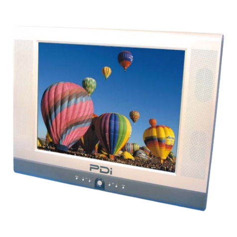
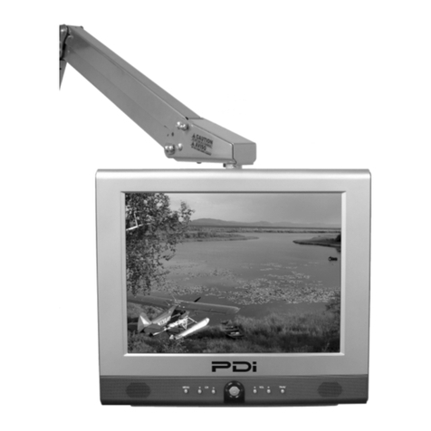
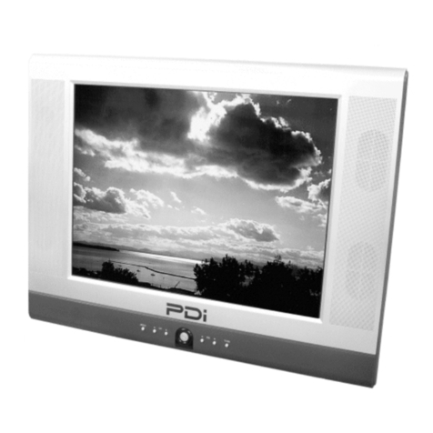
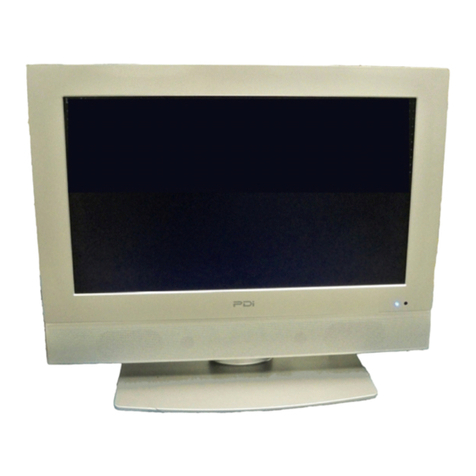
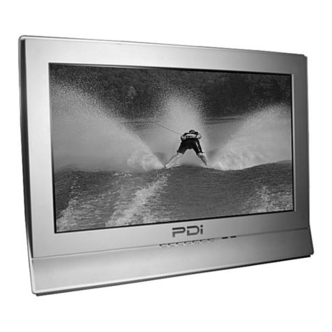
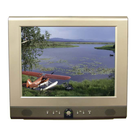
PDi PERSONA 10 User manual

Communication
Systems Inc. PDI-P10LCDD TV Service Manual Page 1 of 32
Better Solutions Are Within Reach™
Service
Manual
Communication
Systems, Inc.
40 Greenwood Lane
Springboro, Ohio 45066
PH: 937-743-6010
FX: 937-743-5664
http://www.pdiarm.com
PERSONA10
Hospital-Grade LCD
Television Receiver
MODEL PDI-P10 LCDD
Better Solutions Are Within Reach®
Document Number: PD196-068R5

Communication
Systems Inc. PDI-P10LCDD TV Service Manual Page 2 of 32
Better Solutions Are Within Reach™
Copyright, Disclaimer, and Trademarks
Copyright
PDI Communication Systems, Inc. claims proprietary rights to the material disclosed in this service manual. This
manual is issued in confidence for servicing information only and may not be used to manufacture anything shown
herein. Copyright 2009 by PDI Communication Systems, Inc. All rights reserved.
Disclaimer
The author and publisher have used their best efforts in preparing this manual. PDI Communication Systems, Inc.
makes no representation or warranties with respect to the accuracy or completeness of the contents of this manual
and specifically disclaim any implied warranties of merchantability or fitness for any particular purpose and shall in
no event be liable for any loss of profit or any other damages, including but not limited to special, incidental,
consequential or other damages. The information contained herein is believed to be accurate, but is not warranted,
and is subject to change without notice or obligation.
Trademarks
All brand names and product names used in this manual are trademarks, registered trademarks,
or trade names of their respective holders.
PDI and Better Solutions Are Within Reach are registered trademarks of PDI Communication
Systems, Inc., Springboro, Ohio.
Regulatory Information
FCC
This equipment has been tested and found to comply with the limits for a Class B digital device, pursuant to part
15 of the FCC Rules. These limits are designed to provide reasonable protection against harmful interference
when the equipment is operated in a residential or commercial installation. If this equipment does cause harmful
interference to radio or television reception, which can be determined by turning the equipment off and on, the
user is encouraged to try to correct the interference by one of more of the following measures:
•Reorient or relocate the receiving antenna.
•Increase the separation between the equipment and receiver.
•Connect the equipment to an outlet on a circuit different from that to which the receiver is connected.
•Consult the dealer or an experienced radio/TV technician for help.
Underwriters Laboratories
The model PDI-P10LCDD Hospital Grade LCD TV is a specialized LCD television and
should be installed to National Electrical Code specifications. This device is safety tested
and listed by the Underwriters Laboratories as a product suitable for use in healthcare
facilities in both the United States and Canada.
Document Number: PD196-068R5

Communication
Systems Inc. PDI-P10LCDD TV Service Manual Page 3 of 32
Better Solutions Are Within Reach™
Product Identification
Product Label
The P10LCDD is easily identified using the product label located in the center of the back housing.
Serial Number
The serial number is located at the lower right corner of the product label.
Serial Number Format Explanation
a. The first two digits compose the year of manufacture. 2009 would be 09.
b. The second two digits compose the week of manufacture. 22 would be week 22.
c. The single alphabetic character represents the place of manufacturing.
d. The next three alphanumeric characters compose the unique model ID.
e. The next six digits compose the serial number starting with the first unit produced in the current year.
f. The last character is the Revision Level.
Document Number: PD196-068R5

Communication
Systems Inc. PDI-P10LCDD TV Service Manual Page 4 of 32
Better Solutions Are Within Reach™
Warnings
Graphical Symbols
This lightning flash with arrow symbol, within an equilateral is intended to alert the user of the presence of un-
insulated “dangerous voltage” within the product’s enclosure that may be of sufficient magnitude to constitute a risk
of electric shock to persons.
The exclamation point within an equilateral triangle is intended to alert the user of the presence of
important operating and maintenance (servicing) instructions in the literature accompanying the
appliance.
This service manual contains various CAUTIONS and WARNINGS indicated by triangular warning
symbols, which should be read and understood in order to minimize the risk of personal injury to
service personnel and customers. The possibility exists that improper service methods may damage
the equipment or result in property damage or user injury. It is also important to understand that
these CAUTIONS and WARNINGS are not exhaustive.
PDI could not possibly know, evaluate, and advise the service industry of all conceivable methods in which
service might be done or of the possible hazardous consequences of each method. Accordingly, a
technician who uses a service procedure or tool which is not recommended by PDI must first satisfy
themselves thoroughly that neither their safety nor the safe operation of the equipment will be compromised
by the service method selected.
Product Safety Servicing Precautions
1 MODIFICATIONS Do not attempt to modify this product in any way
without written authorization from PDI. Unauthorized modifications
will not only void the warranty, but may lead to you being liable for
any resulting property damage or user injury.
2 POWER SOURCE Use only a power source from a CSA Certified /
UL Approved Class 2 Power Supply suitable for use in a healthcare
facility. This TV will operate on either DC or AC voltage.
Voltage Range
AC 18-32
volts
DC 18-32
volts
3 X-RAYS X-Ray radiation is not a concern since this TV does not
incorporate a CRT.
4 REPLACEMENT PARTS. Parts critical to the safe operation of this
TV are pictured in this manual.
Replace only with the part number specified.
5 SAFETY CHECKS This hospital grade TV requires special
safety checks before returning to service. Observe and follow the
“Safety Check” section (page 31) in this service manual.
Document Number: PD196-068R5

Communication
Systems Inc. PDI-P10LCDD TV Service Manual Page 5 of 32
Better Solutions Are Within Reach™
Table of Contents
Copyright, Disclaimer, and Trademarks.................................................................................. 2
Regulatory Information............................................................................................................ 2
Product Identification.............................................................................................................. 3
Warnings................................................................................................................................. 4
Product Safety Servicing Precautions..................................................................................... 4
Picture Adjustments ................................................................................................................ 5
Disinfecting and Cleaning ....................................................................................................... 6
Exploded diagram.................................................................................................................... 7
Replaceable Parts............................................................................................................. 8 -12
List of tools............................................................................................................................ 12
Main circuit board layout and interconnects.......................................................................... 13
Disassembling..................................................................................................................14-20
Reassembling ..................................................................................................................21-30
Safety checks........................................................................................................................ 31
Troubleshooting ...............................................................................................................31-32
Picture Adjustments
The LCD display does not use magnetic deflection (like a CRT tube display) and does not require any internal
adjustments. Dynamic picture adjustments to Brightness, Contrast, Color, and Tint are available using the IR
Remote Control, part number PD108-420, using the SETUP / Picture menu.
Document Number: PD196-068R5

Communication
Systems Inc. PDI-P10LCDD TV Service Manual Page 6 of 32
Better Solutions Are Within Reach™
Disinfecting and Cleaning
The P10LCDD should be disinfected before performing any service. The following procedure is only a
recommendation. Your hospital or company may have a different procedure to follow.
CAUTION – Before using any cleaning or disinfecting
agent on the P10LCDD, perform a spot check by wetting
a small area of the cabinet. Verify the agent does not
discolor or deteriorate the cabinet.
Disinfecting
1. The P10LCDD has been designed to withstand up to a 25% chlorine based disinfectant.
Many alcohol and ammonia based disinfectants have also been tested with success.
However, before using any cleaner or disinfectant, spot check a small area on the
cabinet.
2. Apply the cleaner or disinfectant per its recommended instructions.
NOTE: Most disinfectants require a waiting time following application and prior to wipe-down.
Cleaning
Stubborn ink and other scratch type marks may prove difficult to remove. A dilute solution of Isopropyl
alcohol will generally work when all else fails. However, full strength Isopropyl will remove the cabinet’s
paint. Use with caution!
Document Number: PD196-068R5

Communication
Systems Inc. PDI-P10LCDD TV Service Manual Page 7 of 32
Better Solutions Are Within Reach™
Replaceable Parts - Exploded diagram
This diagram shows the order that the different parts of the P10LCDD fit together.
List of tools
1 Phillips screwdriver
2 3/8-inch socket wrench for four 10-32 nuts
3 7/16-inch wrench
4 Flathead screwdriver
Document Number: PD196-068R5

Communication
Systems Inc. PDI-P10LCDD TV Service Manual Page 8 of 32
Better Solutions Are Within Reach™
EMI Shield
The EMI Shield mounts over the TV’s main board and provides protection from electromagnetic interference.
EMI Shield
Part #: PD130-001
Housing
Components include the front with crystal clear window and foam seals, rear housing, and swivel assembly.
NOTE: The keypad shown with the front housing is sold separately. (See page 8 for more information)
INOVA-10 Front Housing INOVA-10 Rear Housing
Part #: PD133-586 Part #: PD133-587
Document Number: PD196-068R5

Communication
Systems Inc. PDI-P10LCDD TV Service Manual Page 9 of 32
Better Solutions Are Within Reach™
INOVA-10 Swivel Assembly
Part #: PD290-100
Keypad
The keypad fits into the cavity below the speaker vents on the front housing.
Keypad
Part #: PD134-237
LCD Panel
The LCD panel is what displays the images the TV receives. The panel is mounted to the chassis by 2 brackets
and 4 screws. The brackets come attached to the panel.
LCD panel Part #: PD289-110
Document Number: PD196-068R5

Communication
Systems Inc. PDI-P10LCDD TV Service Manual Page 10 of 32
Better Solutions Are Within Reach™
Replaceable Parts
Chassis
The circuit board and the LCD panel are attached to the chassis. It also helps give the unit rigidity.
Chassis
Part #: PD186-001
Speaker Assembly
The speaker assembly attaches to the front cabinet and is replaceable.
Speaker Assembly
Part #: PD106-431
Document Number: PD196-068R5

Communication
Systems Inc. PDI-P10LCDD TV Service Manual Page 11 of 32
Better Solutions Are Within Reach™
Replaceable Parts
Swivel Assembly
The swivel assembly allows the TV to be tilted and panned. It also houses the coax and USB cables.
Swivel Assembly
Part #: PD290-100
Main Coax Cable USB cable for cloning
Part #: PD106-506 Part #: PD106-532
Document Number: PD196-068R5

Communication
Systems Inc. PDI-P10LCDD TV Service Manual Page 12 of 32
Better Solutions Are Within Reach™
Replaceable Parts
Main board
This is the circuit board where the LCD panel, inverter, F-connector, and keypad are connected.
Main board
Part #: PD128-1434
IR Board
This is the circuit board where the speaker assembly and keypad are connected.
IR Board
Part #: PD128-1435
Document Number: PD196-068R5

Communication
Systems Inc. PDI-P10LCDD TV Service Manual Page 13 of 32
Better Solutions Are Within Reach™
Document Number: PD196-068R5
Main circuit board layout and interconnections
LCD backlight
Connector
Earphone jack
Coax RF Power—
“F” Connector
Keypad
Connector
LCD panel
Connector
USB cable
Connector

Communication
Systems Inc. PDI-P10LCDD TV Service Manual Page 14 of 32
Better Solutions Are Within Reach™
Disassembling
Step 1
Picture 1D
Lay the P10LCDD face down on a soft work surface. (Picture 1D)
Step 2
Picture 2D
Remove the socket cap with an Allen wrench. (Picture 2D)
Document Number: PD196-068R5

Communication
Systems Inc. PDI-P10LCDD TV Service Manual Page 15 of 32
Better Solutions Are Within Reach™
Disassembling
Step 3
Picture 3D
Use a Phillips screwdriver to remove the 7 screws from the rear housing. (Picture 3D) Remove the rear housing
from the unit.
Step 4
Picture 4D
Use a Phillips screwdriver to remove the 8 screws from the EMI Shield. (Picture 4D) Remove the shield from the
unit.
Document Number: PD196-068R5

Communication
Systems Inc. PDI-P10LCDD TV Service Manual Page 16 of 32
Better Solutions Are Within Reach™
Disassembling
Step 5
Picture 5D
Before handling the main board be sure that you have taken precautions to protect it and other the
parts from Electrostatic Discharge.
There are 5 connectors on the main board that must be detached before it is removed from the chassis. They are
the backlight, keypad, LCD panel, USB cable, and coax cable connectors. (Picture 5D) (See main circuit board
layout and interconnections diagram on page 13) Use a 7/16-inch wrench to remove the RF connector. A small, flat
screwdriver can be used to assist in the removal of the other connectors. There are locking mechanisms on the
keypad and LCD connectors. These need to be pulled out before the flex cables can be disengaged.
Step 6
Picture 6D
Use a Phillips screwdriver to remove the 5 screws that connect the main board to the chassis. Remove the main
board from the chassis. (Picture 6D)
Document Number: PD196-068R5

Communication
Systems Inc. PDI-P10LCDD TV Service Manual Page 17 of 32
Better Solutions Are Within Reach™
Disassembling
Step 7
Picture 7D
Remove the IR board (PD128-1435) by pinching on each of the two prongs on the front housing that it is placed
on and lifting up on the board. (Picture 7D)
Step 8
Picture 8D Picture 9D
Detach the speaker assembly cable from P2. (Picture 8D) Then, remove the keypad cable from P1. (Picture 9D)
These are connected to the bottom of the IR board. There is a locking mechanism that slides out and must be
disengaged prior to removing the keypad cable.
Document Number: PD196-068R5

Communication
Systems Inc. PDI-P10LCDD TV Service Manual Page 18 of 32
Better Solutions Are Within Reach™
Disassembling
Step 9
Picture 10D
Use a Phillips screwdriver to remove the 2 screws that connect the speaker assembly to the front housing.
Remove the speaker assembly from the front housing. (Picture 10D)
Step 10
Picture 11D
Use a 3/8-inch socket wrench to remove the swivel assembly from the chassis by removing the 4 lock nuts.
(Picture 11D) (To remove the main coax and USB cable extension assembly see step 14 on page 20)
Document Number: PD196-068R5

Communication
Systems Inc. PDI-P10LCDD TV Service Manual Page 19 of 32
Better Solutions Are Within Reach™
Disassembling
Step 11
Picture 12D
Use a Phillips screwdriver to remove the 12 screws that connect the chassis to the front housing. (Picture 12D) Lift
up on the bottom end of the chassis and remove the keypad cable that is threaded through the slot on the chassis.
Remove the chassis from the front housing. The LCD panel is still attached to the chassis, so be careful when
lifting the chassis from the housing.
Step 12
Picture 13D
Use a Phillips screwdriver to remove the 4 screws that connect the chassis to the LCD panel. (Picture 13D) Lift up
on the right side of the chassis and remove the LCD panel cable located in the slot at the bottom, right side of the
chassis. Then lift up the left side of the chassis and remove the backlight cables that are threaded through the
slot on top, left side. Remove the chassis from the LCD panel.
Document Number: PD196-068R5

Communication
Systems Inc. PDI-P10LCDD TV Service Manual Page 20 of 32
Better Solutions Are Within Reach™
Disassembling
Step 13
Picture 14D
Remove the keypad from the front housing. If it cannot be removed from the front housing cavity, contact technical
support. (Picture 14D)
Step 14
Picture 15D
Cut the Ty-rap that is around the USB cable and main coax cable extensions and slide the cables through the
swivel assembly. (Picture 15D)
Document Number: PD196-068R5
Other manuals for PERSONA 10
2
Table of contents
Other PDi LCD TV manuals
