PDX.GOLD STAR-150 User manual
@pdx.gold
contact@pdx.gold
503.783.6550
www.pdx.gold
20209 SW 95th Ave. Tualatin, OR 97062

WELCOME 3
PRECAUTIONS & SAFETY 4
SPECIFICATIONS 5
INSPECTION & RECEIVING 6
SYMBOLS & WARNINGS 7
PRODUCT OVERVIEW 8
EVAPORATION PRESSURES 10
FILTER DRYER 11
INSTALLATION 12
OPERATION 14
MAINTENANCE 15
CERTIFICATION 16
WARRANTY 18
TABLE OF CONTENTS

Hello and welcome to the PDX.GOLD family. We understand there are a lot of choices
in the marketplace for botanical recovery systems, so we are delighted you have
chosen to invest in us.
We designed our Solvent Transfer and Recovery pumps with you in mind and sincerely
hope you notice the difference in quality and safety standards that set us apart from
our competitors. We built this machine to last and want you to enjoy the benefits of its
durability for years to come.
Sincerely,
PDX.GOLD
WELCOME

4
!
WARNING:
THE STAR-150 IS DESIGNED FOR HIGH VOLUME RECOVERY AT PRESSURES BELOW 150PSI. IT
HAS SAFETY PRESSURE VALVING TO LIMIT THE SYSTEM PRESSURE TO 150 PSI.
DEADHEADING YOUR PUMP FOR ANY SIGNIFICANT TIME AGAINST PRESSURES AT OR ABOVE
150PSI GENERATES EXCESSIVE HEAT AND WILL DAMAGE THE PUMP OVER TIME. ALWAYS
ENSURE YOUR SOLVENT RECOVERY TANK HAS CAPACITY TO RECOVER THE SOLVENT IN
THE SYSTEM. WE RECOMMEND A PRESSURE BELOW 110PSI AT STARTUP.
ADJUSTING OR ATTEMPTING TO ADJUST ANY SAFETY OR SYSTEM REGULATING HARDWARE
IS DANGEROUS AND VOIDS ALL WARRANTIES.
CAUSES OF EXCESSIVE RECOVERY PRESSURE INCLUDE: ENTRAPPED ATMOSPHERE IN
THE STORAGE VESSEL AND INSUFFICIENT POST PUMP HEAT CONTROL, RESULTING IN A
TANK TEMPERATURE RISE.
HIGHER PRESSURE CAUSES THE EQUIPMENT TO WORK HARDER. ANY TIME YOU ENCOUNTER
SIGNIFICANT MACHINE VIBRATION, TURN OFF THE SYSTEM IMMEDIATELY AND REMEDY THE
CONDITION CREATING THE VIBRATION BEFORE PROCEEDING ANY FURTHER!
! Unit must be installed in a lab designed to accommodate explosive atmospheres.
R600 / R600a / Propane must be handled in compliance with all federal, state and local safety and
environmental requirements.
1. Do not use this recovery system without reading this manual in its entirety.
2. Always perform the “Pre-Flight Check”, outlined in the Operations section of this
manual prior to using the recovery system.
3. Always confirm there is ample space in the recovery vessel prior to solvent recovery.
Due to the relatively low density of these gases, internal float switches often do not
work, so an electronic scale is recommended.
4. Do not attempt to overfill the recovery tank.
5. Always utilize proper ventilation with explosion proof fans and exhaust systems.
6. Do not allow liquid or gaseous solvent to come in contact with exposed skin,
mucous membranes or eyes.
!
PRECAUTIONS & SAFETY
5
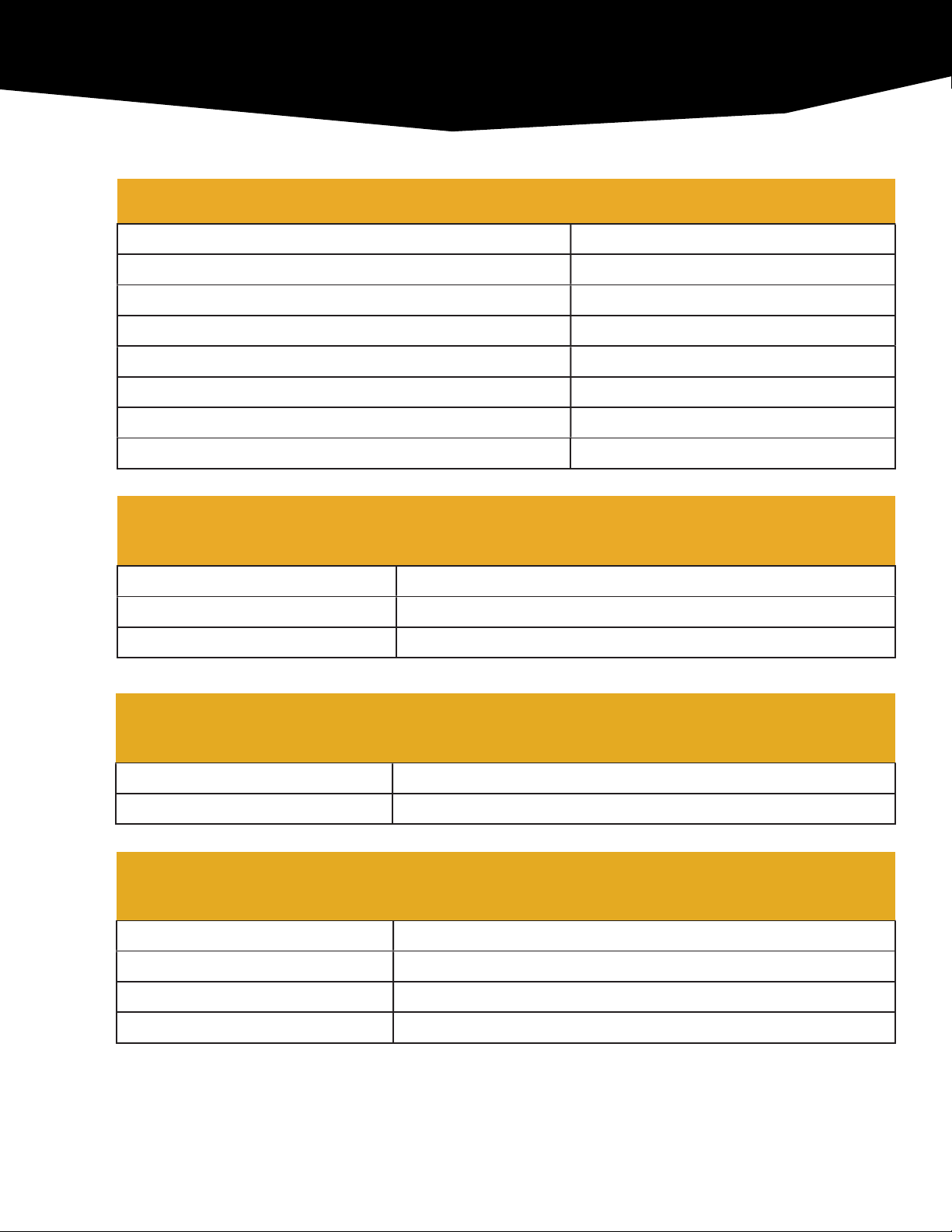
Specifications
Maximum Output Pressure 150 PSI
Motor Size 2 HP (single phase / 3-phase)
Pump Displacement 6.18 In.3
Noise Level 78 dB
Free Air Displacement 20 lbs/hr
Maximum Recovery Rate 15 CFM
Pressure Relief Valve 150 PSI
Applicable Media Butane, Propane, Propane / Blends.
Electrical
Requirements
115v / 208-230v Installation 50 / 60Hz, 30 Amps
230v / 460v Installation 50 / 60Hz, 30 Amps
Watts 1,500
Plumbing
Connections
Pump Input ½” tube fitting (Swagelok compatible)
Pump Output ½” tube fitting (Swagelok compatible)
Physical
Characteristics
Shipping Weight 195 lbs
Machine Weight 145 lbs
Shipping Dimensions 30” Length x 18” Width x 16” Height
Operating Dimensions 30” Length x 18” Width x 16” Height
SPECIFICATIONS

6
UNPACKING AND INSPECTING
Do not proceed if there is any evident shipping damage. Stop at
once and photograph the unit and packaging materials.
1. Once visual inspection has verified no obvious damage has occurred during
shipment, carefully uncrate the unit.
2. If the unit looks damaged, stop at once and call PDX.GOLD Customer Service.
3. Remove the unit from the pallet.
4. Use two people to lift the unit off the pallet, and position near the extractor.
5. If not already shown below, record the model number and serial number of your unit in the
space provided and maintain this record for future reference.
Use this space below to record the data plate information of your specific unit. The data plate is
located on the baseplate, opposite the motor. Use blank spaces to record your internal
information if required eg: sales order, purchase order number, installer initials, etc.
UNIT
INFORMATION
Model Number STAR-150
Serial Number
Certification Number
Date of Purchase
Notes
INSPECTION & RECEIVING
STOP
7
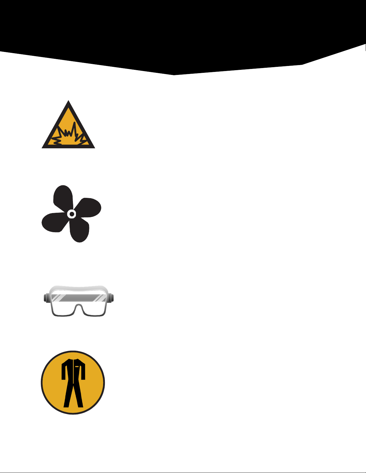
As this recovery system compresses butane and propane, both
flammable gases, this machine must be kept in an explosion-proof
lab that meets environmental, safety and other regulations.
Explosion Hazard: NO smoking, NO open flames, NO sparks
Do not use STAR-150 without proper ventilation.
Eye protection is strongly encouraged while using this machine.
Protective clothing: Fire resistant coveralls or jumpsuit is highly
recommended. Although working with a CLE (closed loop extractor)
drastically cuts down the risk of an explosive environment, we
strongly suggest anyone operating the STAR-150 wear fire resistant
clothing due to the flammable nature of butane and propane.
SYMBOLS & WARNINGS

8
Key Components
1. INPUT connection
2. OUTPUT connection
3. Explosion Proof junction box
4. NEMA 7 2HP motor
Theory of Operation
5. Solvent compressor
6. 150psi Pressure Relief Valve
7. Case Pressure Relief Valve
This solvent transfer and recovery system transfers solvent gas within a closed loop extractor and
returns it, under pressure (up to 150 psi), to a recovery tank for isolation and storage. The STAR-150
requires 230v power which must be connected to a power source by a licensed electrician. The
internal components are all food grade and are comprised of aluminum, stainless steel, iron, and
Viton and Buna-N elastomers.
PRODUCT
OVERVIEW
1
2
7
5
6
4
3

9
Component Overview
When viewing the top of the STAR-150, the input connection is located nearest to the belt
guard. The unit is shipped with a tag identifying this “INPUT”. The input connection is ½”
tube fitting (Swagelock compatible).
When viewing the top of the STAR-150, the output connection is located over the motor,
furthest from the belt guard. The unit is shipped with a tag identifying this “OUTPUT”. The
input connection is ½” tube fitting (Swagelock compatible).
Pressure Control System: The STAR-150 is rated to operate up to 150 psi internal pressure.
If the pressure in the system exceeds 150 psi, the pressure relief valve will activate and
recirculate high pressure gas to the input side of the system and limit system pressure to
150psi.
When this occurs, NO SOLVENT IS BEING TRANSFERRED to the recovery vessel.
Shut off the system and relieve pressure in the recovery tank before restarting.
Deadheading the system in this manner for any significant time at or above 150psi generates
excessive heat and will damage the pump over time. ALWAYS ensure your solvent recovery
tank has capacity to recover the solvent in the system.
IMPORTANT NOTE:
The recovery system may begin to draw negative pressure as the extractor evacuates. While
this is normal and is part of the design operation of the pump – it is NOT INTENDED AS A
VACUUM PUMP. Continued use of the system at vacuum levels greater than 15 in-Hg will
result in damage to the seals and drawing atmospheric air into the system
Many factors will influence pressure readings observed during processing:
- Temperature variance between input gas and output recovery vessel will have
a dramatic impact on recovery speed.
- Type of solvent used. This machine runs butane, propane, and blends of the two.
The observed recovery speed will vary based on the solvent you choose.
PRODUCT OVERVIEW

10
TEMPERATURE
MIXTURE
Propane
C3 H8
100
70
50
30
0
Butane
C4 H10
0
30
50
70
100
º
F
-44 0 0 0 0 0
-30 6.8 0 0 0 0
-20 11.5 4.7 0 0 0
-10 17.5 9 3.5 0 0
0 24.5 15 7.6 2.3 0
10 34 20.5 12.3 5.9 0
20 42 28 17.8 10.2 0
30 53 36.5 24.5 15.4 0
40 65 46 32.4 21.5 3.1
50 78 56 41 28.5 6.9
60 93 68 50 36.5 11.5
Vapor Pressure
(psig)
EVAPORATION PRESSURES

11
Ingesting ANY substance other than solvent vapor into the compressor is not
considered normal or customary use. Foreign matter is considered contamination
(extracted oils / organic byproducts / dirt / etc.), may damage the pump and void your
warranty.
To ensure peak performance of your solvent transfer and recovery system, we strongly
recommend the user to install a molecular sieve / solvent filter-dryer in the system before the
input of the pump.
The STAR-150 is a high-performance solvent transfer and recovery pump and may
overwhelm many types of filter-dryers. PDX.Gold has designed our own filter dryer, the
CycloneDry, which may be configured for ANY size extraction system. CycloneDry is a
modular system - simply daisy-chain any number of CycloneDrys to your recovery system (via
stainless steel braided hoses) to keep up with your level of processing.
CycloneDry are available in 3 sizes with the input fitting, output fitting and a pressure relieve
valve on the top of the unit. Constructed of stainless steel, assembled with explosion proof tri-
clamps and Viton or Buna-N gaskets. The CycloneDry is designed to accommodate two, three
or four desiccant filter cores (depending on the size selected) to absorb water vapor or oil and
works in two ways:
1. As the solvent is drawn in by the pump, the CycloneDry acts as a “cold trap” and
heavier constituents such as water vapor or oil are spun out of the gas, condense on
the sides of the unit and settle to the bottom.
2. The included desiccant filter cores absorb any remaining water vapor and / or
suspended oils and removes them from the solvent gas*.
Filter Core Recharging
During normal use, the filter cores can become saturated with moisture and lose
effectiveness. Cores can be re-conditioned in a vacuum oven and may be reused many times
before requiring replacement if they have not been contaminated with organic material. The
cores will catch vaporous oils on the surface of the cores, which often is visible as a “sheen”
on the desiccant surface. Visible contamination on the cores is an indication it is time to
discard them and replace them with new units. Failure to maintain the cores may allow
contaminants to migrate over time through the desiccant material and into the compressor.
* Reconditioning / replacement of the cores may be required to maintain effective operation if they become saturated or contaminated.
FILTER DRYER

12
Lifting & Handling
The STAR-150 is a precision machine that should be handled with care.
*** We highly recommended that two people lift the unit whenever moving***
Moving the unit over any distance is best achieved with a wheeled cart or a dolly.
The unit has vibration isolating feet that resist “walking” while the unit is in operation.
Environmental Conditions of Operation
The STAR-150 can function in an environment between 35-90°F. The STAR-150 should
remain dry at all times. Poor air quality can result in shorter pump life.
Protect your pump from air-borne dust and debris that can impede ventilation.
Installation Location Requirements
The STAR-150 is intended to be used indoors on a flat surface. The laboratory environment
should comply with all local and state regulations and safety standards. Prior to installation,
consider the power source, location of other equipment and operator comfort and efficiency.
Power Source
The STAR-150 requires a hard-wired connection to a power source.
It is recommended the installation be performed by a licensed electrician.
1. Verify voltage and amperage on the motor datatag.
2. Verify voltage and amperage of the power source.
3. Connect STAR-150 to the appropriate power supply.
INSTALLATION

13
The STAR-150 does not have any manually adjustable settings.
Use valves and control hardware on the extractor to regulate the
flow of gas through the STAR-150.
Power Source Continued
STAR-150 may be fitted with a NEMA 7 plug, connected to a NEMA 7 receptacle
and switch that has been installed according to your state / county safety
regulations within your extraction room.
Connecting the STAR-150 to the Extractor
1. Follow all instructions in this manual closely.
2. Follow all instructions associated with your closed loop extractor closely.
3. Close the solvent input and output valves on the extractor.
4. Using a ½” hose, connect the OUTPUT of the extractor to the INPUT of the STAR-
150. When viewing the top of the STAR-150, the input connection is located
nearest to the belt guard. The unit is shipped with a tag identifying this “INPUT”.
The valve associated with this connection will be referred to in this manual as
“Input Valve”.
5. Using a ½” hose, connect the OUTPUT of the STAR-150 to the INPUT of the
recovery tank on the extractor. When viewing the top of the STAR-150, the output
connection is located over the motor, furthest from the belt guard. The unit is
shipped with a tag identifying this “OUTPUT”.
The valve associated with this connection will be referred to in this manual as
“Output Valve”.
Optimal Operating Pressures
It is recommended the input pressure remains at or below 75 PSI and the output
pressure remains at or below 150 / 120 PSI (STAR-150). If the input pressure
exceeds 75 PSI when the unit is not operating, the case may pressurize and cycle
the pressure relief valve.
!
INSTALLATION

14
The following operation instructions assume the unit has been properly
installed in accordance with all applicable municipal safety, regulatory and legal
compliance. Do not proceed until proper installation has been completed.
Pre-Flight Check
1. Verify all fittings and connections between your extractor and STAR-150 have been
tightened appropriately.
2. Verify the CycloneDry / molecular sieve filter elements are in a new, or reconditioned
state.
* IMPORTANT NOTE: Using old or saturated filter elements will have a negative effect on the life of
your pump and the quality of your product. Drawing moisture and / or organic material into the pump
will void the warranty.
3. Verify both the input and output valves on the closed loop extractor are open BEFORE
turning on the pump. NEVER RUN THE PUMP WITH THE INPUT VALVES OR OUTPUT
VALVES CLOSED.
Power-Up
Once you have verified the installation and checked out the system, it is time to power up.
Depending on your installation, simply plug in your STAR-150 to its designated outlet or activate
the power switch if installed.
Power-Down
1. Close the output valve on the extractor.
2. Turn off the pump.
3. Close the input valve on the solvent recovery tank.
*Notice*
The recovery system may begin to draw negative pressure as the extractor evacuates. While
this is normal and is part of the design operation of the pump – it is NOT INTENDED AS A
VACUUM PUMP. Continued use of the system at vacuum levels greater than 15 in-Hg will
result in damage to the seals and drawing atmospheric air into the system
OPERATION
!

15
WARNING: Disconnect the unit from power supply prior to doing any
maintenance on the STAR-150.
General Maintenance
When cared for and operated properly according to this manual, the unit is essentially
maintenance free and will provide years of dependable service.
THE MOST IMPORTANT THING THE USER CAN DO TO REALIZE A LONG,
TROUBLEFREE PUMP LIFE IS TO TRANSFER CLEAN AND DRY SOLVENT.
EVERY piston pump on the market will be adversely affected by ingestion of contaminants
and ours is no exception to this rule.
This recovery system is an oilless design and requires no oil changes.
Preparing for Shipment
1. Disconnect the pump from the closed loop extractor.
2. Disconnect the molecular sieve / CycloneDry. Clean and store per the instructions
recommended by the manufacturer.
3. Properly package the unit in a shipping container, ensuring the unit is secure inside
the container to prevent movement during shipping.
4. Attach to a standard shipping pallet and band / secure the unit to the pallet for shipping
5. Alternately, store in a dry, clean environment for future use.
MAINTENANCE
!

16
STAR-150 is certified by the third party engineering group, 3PCertz. 3PCertz specializes in
certifying cannabis extraction machines and the rooms in which they reside.
If you have purchased a certified unit, your STAR-150 will have a serial tag provided by 3PCertz
attesting to the fact your machine has been reviewed and held to the utmost standards in
cannabis extraction technology.
PDX.GOLD and 3PCertz offer certification for 34 states and the District of Columbia in the United
States. If your location is not listed, give us a call and we can review getting your location added
to our certification list!
Certified States
Arizona
Arkansas
California
Colorado
Washington D.C.
Florida
Idaho
Illinois
Kansas
Kentucky
Louisiana
Massachusetts
Maryland
Maine
Michigan
Minnesota
Missouri
Montana
North Carolina
North Dakota
Nebraska
New Mexico
Nevada
New York
Ohio
Oklahoma
Oregon
Pennsylvania
South Dakota
Texas
Utah
Vermont
Washington
Wyoming
Certification Report Number
190019
CERTIFICATION

17
Electrical
Part Manufacturer Description
Motor
standard
Leeson NEMA 7, 2 HP, single phase, 1725 rpm.
Motor
optional
Marathon NEMA 7, 2 HP, 3-phase, 1725 rpm.
Fittings &
Hoses
Part Manufacturer Description
Fittings Swagelok / SSP ¼” & ½” 2600 psi working
pressure dual ferrule fittings.
Hoses Detroit Flex / Corlee Stainless steel braided hoses:
Certified high pressure PTFE, smooth
bore hoses, specifically designed for
applications requiring strength, reli-
ability, and long term performance.
CERTIFICATION

WARRANTY
LIMITED USA AND CANADA WARRANTY POLICY – PDX.GOLD warrants products sold against
defects in material or workmanship as follows: PDX.GOLD, at its option, unless otherwise agreed, will replace
or repair any defective product unit or defective part of the product unit at no charge, provided that:
1. The warranty claim is made in writing within the period of time specified in the catalog or in
information enclosed with the product packaging (6 months); and
2. The proof of purchase by bill of sale or receipted invoice is submitted concurrently with the claim
and shows that the product is within the applicable warranty period to Customer Service of
PDX.GOLD; and
3. The purchaser complies with Procedures for Returns listed under the General Terms and
Conditions contained herein; and
4. The purchaser complies with all the manufacturer’s requirements. The warranty is in force from the
date of shipment from PDX.GOLD’s manufacturing facility. The warranty period begins on the
day the customer receives the product, but not later than 90 days after the date of shipment from
PDX.GOLD’s manufacturing facility. PDX.GOLD reserves the right, at its discretion, to fulfill warranty
claim with refurbished or reconditioned parts or units.
This warranty shall not apply to:
a) Defects or damages resulting from (1) misuse of the product, (2) use of the product in other than
its normal and customary manner, (3) accident or neglect, (4) improper testing, operation, main-
tenance, service, repair, installation, or storage, (5) unauthorized alteration or modification, (6)
damage determined to be the result of freight or shipping after the product has left the factory; or
b) Normal tear and wear of the product, its components, or parts; or
c) Post-expiration dated material
Other limitations
This warranty is the exclusive remedy of the purchaser, and PDX.GOLD disclaims all other warranties,
whether expressed, implied or statutory, including without limitation, warranties of merchantability and fitness
for particular purpose. No employee, agent, or representative of PDX.GOLD is authorized to bind PDX.GOLD
to any other warranty. In no event shall PDX.GOLD be liable for incidental or consequential damages.
All expressed and implied warranties, including the implied warranty of merchantability and the implied
warranty of fitness for a particular purpose, are expressly disclaimed and shall not apply to any products sold
or services rendered hereunder. PDX.GOLD shall not be liable for consequential, incidental, special, or other
direct or indirect damages resulting from economic loss or property damage sustained by you or any end user
from use of the products sold or services rendered hereunder.
Table of contents
Other PDX.GOLD Test Equipment manuals


