PEAK INSTRUMENTS C-7200 Series Guide

User Manual PEAK INSTRUMENTS INC
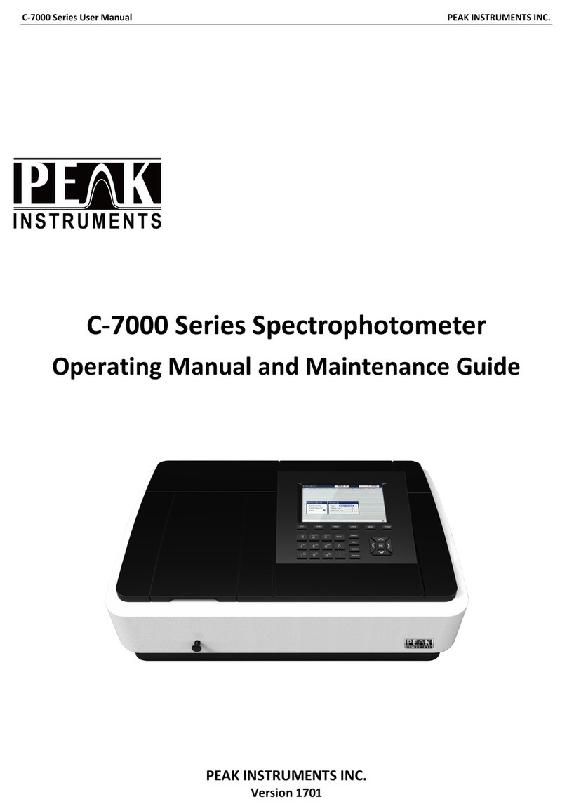
C-7200 Series Spectrophotometer
User Manual and Maintenance Guide
PEAK INSTRUMENTS INC
Version 1801

User Manual PEAK INSTRUMENTS INC
CONTENTS
I. General Information ........................................................................................ 1
1. Safety notes .............................................................................................. 1
2. Product overview ...................................................................................... 2
2.1. Basic operating principles ................................................................. 2
2.2. Performance indicators definitions .................................................... 4
2.3. Applications ...................................................................................... 6
2.4. Using conditions ............................................................................... 6
II. Product Features and Installation................................................................... 7
1. Features ................................................................................................... 7
2. Technical data .......................................................................................... 8
3. Main functions ........................................................................................... 9
4. Structure introduction .............................................................................. 10
4.1 Top view of structure: ....................................................................... 10
4.2. Bottom view of structure: ................................................................ 10
4.3. Light path diagram .......................................................................... 11
4.4. Important part of the instrument ...................................................... 11
5. Instrument installation ............................................................................. 13
III. Key Definitions and Basic Operations ......................................................... 14
1. Panel schematic diagram ........................................................................ 14
2. Button function descriptions .................................................................... 14
3. Basic operations ..................................................................................... 15
IV. Programs .................................................................................................... 15
1. Instrument self-test ................................................................................. 15
2. Photometric masurement ........................................................................ 17
3. Quantitative measurement ...................................................................... 21
3.1. Build standard curve ....................................................................... 21
3.2. Standard sample measuring ........................................................... 22
3.3. Sample test ..................................................................................... 23
3.4. Open standard curve ...................................................................... 23
4. Time scan (Kinetic) ................................................................................. 24
4.1. Function description ........................................................................ 24
4.2. Time scanning parameters set ........................................................ 24
4.3. Data test ......................................................................................... 25
4.4. Data list ........................................................................................... 25
4.5. Slope calculation ............................................................................. 26
5. Wavelength scanning .............................................................................. 26
5.1. Function description ........................................................................ 26
5.2. Set scanning parameters ................................................................ 26
5.3. System baseline ............................................................................. 27
5.4. Create a user baseline (corrected blank) ........................................ 28
5.5. Begin testing ................................................................................... 28
5.6. Peaks and valleys ........................................................................... 29
5.7. Data list ........................................................................................... 29
6. Multi-wavelength test .............................................................................. 30
6.1. Function description ........................................................................ 30

User Manual PEAK INSTRUMENTS INC
6.2. Set parameter ................................................................................. 31
6.3. Correction 100%T/0Abs .................................................................. 31
6.4. Data test ......................................................................................... 32
7. Protein/DNA measurement ..................................................................... 32
7.1. Function description ........................................................................ 32
7.2. Parameter selection ........................................................................ 33
7.3. Set zero .......................................................................................... 33
7.4. Test ................................................................................................ 33
8. System setup .......................................................................................... 34
8.1. Dark current measurements ............................................................ 34
8.2. Looking for deuterium lamp curve ................................................... 35
8.3. Time and date settings .................................................................... 35
8.4. Light source management .............................................................. 36
8.5. General ........................................................................................... 37
8.6. File system ..................................................................................... 37
8.7. USB storage device ........................................................................ 38
8.8. Restore factory settings .................................................................. 38
8.9. System information ......................................................................... 39
V. Maintenance ................................................................................................ 39
1. Cleaning Requirements .......................................................................... 39
1.1. Spectrophotometer ......................................................................... 40
1.2. Display ............................................................................................ 40
1.3. Cuvettes/cells ................................................................................. 40
2. Routine precautions ................................................................................ 41
3. Tungsten lamp replacement.................................................................... 41
4. Deuterium lamp replacement .................................................................. 42
VI. Troubleshooting .......................................................................................... 44
1. Power failure ........................................................................................... 44
2. Self-test failure ........................................................................................ 45
3. Other failures .......................................................................................... 46

User Manual PEAK INSTRUMENTS INC
1
I. General Information
1. Safety notes
• Read the entire user manual carefully before you unpack, set up or operate
the device. Wrong operations could lead to serious injury of the operator or to
damage to the device.
• To make sure that the protection provided by this instrument is not impaired,
do not use or install this instrument in any manner other than that specified in
these operating instructions.
• The source lamps are operated at high temperatures. To avoid the risk of
electrocution, make sure the instrument is disconnected from the power source
before changing the lamps.
CAUTION
Health hazard caused by ozone.
Hazardous levels of ozone can be generated when the UV lamp is not cooled.
WARNING
Health hazard caused by UV light.
UV-Lig
ht can cause eye and skin damage. Protect eyes and skin from direct
exposure to UV light.
Do not look directly at an energized lamp without UV safety glasses.
CAUTION
Burn hazard, allow the lamp(s) to cool down for at least 30 minutes
before they
are serviced/replaced.
DANGEROUS
Potential danger with contact with chemical/biological substances.
Working with chemical samples, standards and reagents can be dangerous.
Make yourself familiar with the necessary safety procedures and the
correct
handling of the chemicals before use and read and follow all
relevant safety
data sheets.
Normal operation of this device may require the use of chemicals or samples
that are biologically unsafe.
• Observe all cautionary information printed on the original solution containers
and safety data sheets prior to their use.
• Dispose of all consumed solutions in accordance with the local and national
regulations and laws.
• Select the type of protective equipment suitable to the concentration and

User Manual PEAK INSTRUMENTS INC
2
quantity of the dangerous material being used.
2. Product overview
2.1. Basic operating principles
2.1.1. The nature of absorption: spectrophotometric analysis method is the use
of substances to choose a different wavelength of light absorption
characteristics established. Typically using a prism or grating to obtain
monochromatic light that passes through the continuous monochromatic
solution, the solution was measured and the absorption of each wavelength, the
absorption spectrum curve obtained.
Absorption spectrum selective absorption of light from the material, which is the
material of macroscopic phenomena, and the nature of the molecular absorption
is the result of internal movement and light interaction. When molecules absorb
certain wavelengths of spectral energy or by some wavelengths of the spectrum
is absorbed to form the absorption spectra. The smaller the energy absorption,
the wavelength of light corresponding to the absorption peak at a longer
wavelength. When the infrared absorbent is formed in the infrared absorption
spectrum, if the energy absorption is larger, the shorter the wavelength
corresponding to the absorption peak at a shorter wavelength, when generating
the ultraviolet absorption spectra of absorption in the ultraviolet region.
2.1.2. Absorption Law - Lambert Beer law: when a parallel beam through the
homogeneous solution, the absorbance of monochromatic light is proportional to
the product of the solution concentration and thickness.
Its digital expression: A=KCL=LogI/I0=-LogT.
Premise absorption laws established numeric expression: ① the incident light is
monochromatic ② the absorption process without interaction of each substance,
the absorbance of each substance has additivity ③ the role of light and matter is
limited to the absorption process, no fluorescent and photochemical scattering
phenomena ④ absorbent system is a continuous uniform distribution
2.1.3. Impact spectrophotometry factors:
2.1.3.1. Non-absorption errors caused by radiation and matter

User Manual PEAK INSTRUMENTS INC
3
2.1.3.2. Fluorescence and photochemical reactions, in general, errors
fluorescence spectrophotometry produced negligible fluorescence efficiency is
very small in most cases the color system, and the fluorescence emission is
isotropic, only a small portion along the transmitted light direction into the
detector, the measurement of absorbance is low, resulting in a negative
deviation. Depends on the instrument to measure the impact on the absorption
of fluorescence great extent on the optical absorption cell and detector design.
2.1.3.3. Reflection and scattering, absorption law applies only to homogeneous
medium absorption system, turbid solution so that the measured increase in
absorbance due to scattering, resulting in deviation from Beer's law
2.1.3.4. Non-ideal instrument error caused
2.1.3.5. Beer's law deviation polychromatic contrast, the majority of the
photometer can only get close to monochromatic light with a narrow lumen, in
fact, there is still a polychromatic nature, can lead to deviations from Beer's law.
Deviation depends on the two monochromatic molar absorptivity difference △ ε,
| △ ε | is very small, can be approximated that monochromatic, at low
concentrations, curve remains linear, but larger concentrations, with
concentration increases, AC curve bend more serious, there is Beer's law
applies only to dilute solutions
2.1.3.6. Stray light, stray light entering the detector means is unnecessary
components to be tested at other wavelengths outside the range of the
wavelength spectral bandwidth. The main dispersive element from a prism or
grating spectrometer, a mirror, a lens surface scattering, dust and other inner
walls of monochromator components and diffuse reflection and other scars, the
stray light can cause serious measurement error. The instrument is the smallest
wavelength of energy, usually at a maximum stray light (such as deuterium lamp
220nm, tungsten lamp 340nm)
2.1.3.7. Slit width, the slit width of the spectrum affects not only the purity, but
also affect the absorbance. When quantitative analysis in order to obtain
sufficient measuring signal, the slit should be larger, in the qualitative analysis of
the use of a smaller slit when the entrance slit and the exit slit width equal to the
width of the slit caused minimum error
2.1.3.8. Wavelength scale ruler of error, the wavelength of the gauge that
wavelength accuracy of the instrument, such as a large error or correction, the

User Manual PEAK INSTRUMENTS INC
4
spectral measurements produce errors that affect the accuracy of absorbance
measurements (in the absorption spectrum of the peak of the more significant )
2.1.3.9. Impact of non-parallel incident, one of the prerequisites ear than the law
is the use of a parallel incident beam to ensure that all beams through the same
thickness of the absorbing medium, when a large deviation from parallelism
when the incident beam, obviously lead to deviations from Beer's law. If the
instrument is in moderate-intensity beam deviation from parallelism, absorbance
measurement error is generally caused by less than 0.5%
2.1.3.10. Photometric scale error, photometric accuracy of the scale that is
transmittance, which directly affects the accuracy of the magnitude of the error
photometric measurements.
2.2. Performance indicators definitions
2.2.1. Optical system: usually refers to the formal structure of the optical system,
at present, domestic and international institutions often used as a photometer
industry type and CT auto collimation two structures;
2.2.2. Wavelength range: means for wavelength photometer can difference
between maximum and minimum values of the test;
2.2.3. Wavelength accuracy means the actual wavelength difference between
the real wavelength and the setting wavelength. Each wavelength photometer to
be in a lot of points to check wavelength accuracy; spectrophotometer
wavelength accuracy is an important technical indicators, it qualitative,
quantitative and structural analysis of the impact is enormous. Way to check
wavelength accuracy of many spectral lines as a standard filter praseodymium,
neodymium, holmium oxide filter, holmium oxide wavelength standard solution,
deuterium lamp or low pressure mercury lamp emission and interference filters
and so on.
2.2.4. Wavelength repeatability: Wavelength Repeatability is the ability of the
instrument to return the original wavelength. It reflects the wavelength drive
mechanism and the stability of the whole instrument;
2.2.5. Spectral bandwidth (sensitivity, resolution): refers to a peak spectral
bands when the slit on the detector detected through a monochromator energy
half-width, expressed in nm wavelength, from another perspective to understand
this concept will more user-friendly: first, the monochromator exit slit represents
not just the physical size or geometry, it also represents the optical sense, this is

User Manual PEAK INSTRUMENTS INC
5
the spectral bandwidth, we know that the light from the failure of a single
monochromator wavelength, but at a narrow wavelength spectral band are
arranged in the order, the number of spectral wavelength band comprises,
represented by the spectral bandwidth. Spectral bandwidth is a direct response
to the quality level of monochromatic light from the monochromator out. The
index with the instrument resolution and sensitivity are similar, but different, they
react photometer performance quality from different sides. Resolution refers to
the size of the instrument to distinguish two adjacent wavelengths ability
Sensitivity is measured at low concentrations do, when the concentration
changes by one unit to the detector signal caused by the change amount, it is
subject to a calibration curve (standard curve as the horizontal axis, the
absorbance on the vertical axis) and a precision instrument itself restrictions.
Two measurement precision of the method is the same, the greater the
sensitivity calibration curve slope, while the slope equal, the higher the
sensitivity, the better precision. It is noted that, in order to obtain accurate test
results, the natural bandwidth of the spectral bandwidth of the instrument
(Spectral Bandwidth referred SBW) and the analysis of samples (Natural
Bandwidth referred NBW) ratio should be less than 0.1, more than 99.5% can
be obtained so that the measurement accuracy.
2.2.6. Stray light: wavelength of stray light is irradiated onto the non-selection
signal generated by the detector. It is an important source of photometric
analysis of errors, stray light limit the accuracy of the General Assembly high
concentration solution analysis. Stray light represented by T%;
2.2.7. Photometric range: Refers to meet the photometric test range in various
technical indicators, represented by A or T;
2.2.8. Photometric accuracy: the true average value refers to the degree of
compliance with a plurality of measured; photometric accuracy check is usually
through the use of repeated measurements of the neutral density filter carefully
film to a standard photometric detection. A neutral density filter for light in a
wavelength range having almost the same transmittance (or absorbance) of the
filter, and the use of its wavelength insensitive characteristic bandwidth
changes, to check the accuracy of the optical instrument and repeatability.
2.2.9. Photometric Repeatability: refers several times under the same
conditions as measured in parallel, each parallel line with the degree of
determination between the results;

User Manual PEAK INSTRUMENTS INC
6
2.2.10. Noise: the sum of the instrument detects the unwanted signals, which is
the purpose of the relative signal. Generally, the spectrophotometer has two
sources of noise, one from the light source, the second is derived from the
internal electronic noise inherent in the instrument, such as: power supply,
amplifier, AD conversion and the like. To reduce noise, improve signal to noise
ratio, there must be a good electrical design. Noise measurement repeatability
test under low concentrations, but also affect test accuracy. Noise by averaging
several measurements after partial elimination;
2.2.11. Drift: refers to the degree of deviation from the instrument over time the
starting value. It depends on the stability, light stability of the electrical device
and the like. Single-beam instrument, the warm-up time has a great influence
on the length of the drift.
2.2.12. Baseline flatness: refers to the distribution of the full wavelength range of
the instrument noise.
2.3. Applications
Subjects available for physics, chemistry, medicine, biology, pharmacology,
geology and other scientific research, is widely used in chemical,
pharmaceutical, biological and chemical, metallurgy, light industry, materials,
environmental protection, medicine and other industries and laboratory analysis
of the industry's most one important quality control instruments, is essential for
routine laboratory instruments.
2.4. Using conditions
Equipment should be installed away from the hot or humid environment. The
instrument should be used in 16-35 ℃, 45-80% humidity conditions. Please try
to stay away from issuing magnetic, electric, high-frequency waves of electrical
devices, do not install the instrument in the air chlorine, hydrochloric acid gas,
hydrogen sulfide gas, such as sulfurous acid gas, corrosive gas Excessive
places. Place the instrument table should be smooth, without vibrations; nearby
fan of the instrument should be left enough space to exhaust smoothly.
Instrument is best to use a single power outlet, power should ensure good
grounding. Doing so may result in equipment not working properly. If the local
voltage instability, give the instrument is equipped with power supply. The
instrument should avoid direct sunlight. Avoid dusty environments.

User Manual PEAK INSTRUMENTS INC
7
II. Product Features and Installation
1. Features
With low stray light and a high resolution structure of double-beam optical
monochromator, the instrument has a good stability, reproducibility and
accuracy of readings.
Not only the instrument has automatically set 0% T and 100% T and other
control functions as well as the concentration of computing and data processing
functions of a variety of methods, but also to prevent user errors with special
features, no worries when using . Scientific design, the use of new technologies,
the optical, mechanical, electrical and computer technology combined with
organic, both to improve product performance and convenience for users to use.
Large graphic LCD screen can display the data and maps. The extensive
machine software can complete quantitative analysis, qualitative analysis,
kinetics, DNA/Protein and other tests. Coupled with powerful storage and
printing capabilities, the computer can complete all testing, analysis and data
output with no connection with PC.
Optional equipment is also available on the Windows platform running UV
Professional user application software, the instrument has greater functionality.

User Manual PEAK INSTRUMENTS INC
8
2. Technical data
Model C-7200 C-7200S
Display 7 inch TFT
Keyboard
Control Silicone Buttons
Optical System Double Beam
Holographic grating, 1200 lines/mm
Slit Width 2nm 1 nm
Wavelength
Range 190 - 1100nm
Wavelength
Accuracy
±0.3nm
Wavelength
Repeatability ≤0.1nm
Photometric
Accuracy
0.2%T(0-100%T), ±0.002A(0-0.5A), ±0.004A(0.5-1A)
Photometric
Repeatability ≤0.15%T(0-100%T), 0.001A(0-0.5A), 0.002A(0.5-1A)
Stray Light ≤0.03%T@220nm,360nm
Stability ±0.001A/h@500nm
Photometric
Range 0-200%T, -0.3-3.0A, 0-9999C(0-9999F)
Baseline
Flatness ±0.0015A(200-1000nm)
Noise 0.0003A@500nm
Working Mode T,A,C,E
Wavelength
Setting
Automatic
Scanning Speed
High, Medium and Low
Detector Solid Silicon Photodiode
Light Source Tungsten Halogen/Deuterium Lamp
Data Output RS232C Serial, USB Drive, USB HOST
Processor Cortex_M3, 120Mhz
Power
Requirements
AC 220V
/50Hz
Shipping
Dimensions and
Weight
770*630*340mm, 27kg

User Manual PEAK INSTRUMENTS INC
9
3. Main Functions

User Manual PEAK INSTRUMENTS INC
10
4. Structure Introduction
Overall structure consists of three parts: optical system, power system
and micro-computer system.
4.1 Top view of structure:
4.2. Bottom view of structure:

User Manual PEAK INSTRUMENTS INC
11
4.3. Light path diagram
4.4. Important part of the instrument
4.4.1. Power Board: The 110-220V/50Hz-60Hz power conversion and regulation
outside access to the necessary equipment: 11.5V (tungsten lamp power), +12
V (fan power, electrical power), +5 V (computer system power), + /-15V (signal
board power supply), deuterium lamp filament preheating and lit power
deuterium lamp is lit up and the power breakdown.
4.4.2. Light room: there are tungsten halogen lamp and deuterium lamp source
device to automatically switch.
Tungsten halogen: visible spectral region. Applicable wavelength range 340-
1100nm. Because it uses the principle of halogen cycle, it has a greater
intensity of light emission and longer life. As the halogen cycle requires a higher
temperature. Thus lamps commonly used quartz glass or high temperature
glass. Tungsten halogen lamps emit energy in the visible region around the
operating voltage is proportional to the fourth power, therefore, to make light
stable, the model has a stability of less than 0.2% of the power supply, the other
imported Philips halogen socket tungsten halogen lamp replacement to ensure
stable and easy to use and long life.
Deuterium lamp: suitable wavelength range of 190-340nm. When deuterium
lamp operation, maximum energy sources in the vicinity of 230nm, 486.0nm and

User Manual PEAK INSTRUMENTS INC
12
656.1nm and has two characteristic lines, can be used for instrument calibration
wavelength accuracy in the visible region. Stability of the steady flow of less
than 0.02% of the models, to ensure stable deuterium lamps, imported from
Japan, Hitachi another seat belt deuterium lamp replacement lamps to ensure
the convenience and use of the stability and long life.
4.4.3. Monochromator: contains spectral components - grating, into the slit, the
slit, mirror, focusing lens, and the wavelength filter drive system, the
monochromatic light is emitted from the composite light can be decomposed
into monochromatic any wavelength of monochromatic light from the optical
separation means
Raster: the dispersion of the original, the model uses 1200 / mm holographic
grating ensure high resolution and low stray light.
Filter: Due to the grating spectrum spectral overlap exists between the problem
class times, so the use of filters to eliminate spectral overlap problem.
Action slits, the slits in the monochromator is large, and the resolution of the
instrument is not only related to the dispersion of the grating and the size of the
image (i.e., the slit width). The slit is too large, color band is deteriorated, is not
conducive to the qualitative analysis, quantitative analysis also affect the linear
range of the calibration curve, the slit is too small, flux decreased, reducing the
signal to noise ratio, affect the measurement accuracy, the slits there are two
general representation of the width, the actual width of the slit of a knife-edge
between the two expressed (in mm), the other to represent the bandwidth of
spectral bands (in nm).
4.4.4. Spectroscopic Room: contains a half-mirror, focusing lens and reflector to
achieve a beam monochromator out into two beams of light in different
directions
4.4.5. Sample Chamber: fixed 2-position cuvette holder, one is for reference
solution, and the other is for sample solution. 8-position cell changer is optional.
4.4.6. Signal Board: Transfer to the motherboard processed signal detection
light amplification
4.4.7. Main board: instrument micro control unit, control instruments light source
switch, the motor rotates, the signal processor display, etc.

User Manual PEAK INSTRUMENTS INC
13
5. Instrument installation
5.1. After unpacking, carefully check the packing list inside if the object is
complete and intact;
5.2. Determine whether the work environment to meet the foregoing
requirements, the ambient temperature 10 ~ 35 ℃, relative humidity less than
85%, operating voltage 110-220V/50-60HZ.
5.3. The instrument is placed on a horizontal platform, the instrument should
avoid direct sunlight and be away from electromagnetic launchers and high-
power electrical devices, the use of the environment can’t have dust, corrosive
gases and vibration;
5.4. Around the instrument no obstacle to the flow of air around the instrument;
5.5. The company supplied with a power cord and make sure there are well-
grounded power outlet line;
5.6. Check the sample chamber, ensure that there is not any solution, and
foreign matter and the process of self-test to ensure that the sample
compartment lid is closed, you can’t half-open (this is very important otherwise
affect the instrument self-test results and normal use!).
5.7. Turn on the instrument. Then the instrument make self-test. After that, the
instrument can be operated normally. In case there is an error alarm halfway,
please refer to the chapter of instrument troubleshooting.
Note: Use only a grounded socket for the connection of this device to the power
supply. If you are not sure if the sockets are grounded, have this checked by a
qualified electrician. The power plug serves in addition to the power supply to
isolate the device quickly from the power source where necessary. During the
disconnection from the power source it must be made sure that the correct
power plug is pulled (for example by labeling the sockets). This is recommended
for long-term storage and can prevent potential dangers in the event of a fault.
Therefore make sure that the socket to which the device is connected is easy to
reach by each user at all times.

User Manual PEAK INSTRUMENTS INC
14
III. Key Definitions and Basic Operations
1. Panel schematic diagram
2. Button function descriptions
Button name Button functional description
【MENU】 Menu key under each function
【PRINT】 Print output button
【SAVE】 File storage button
【LOAD】 File open button
【ESC】 Back, cancel button, test stop button
【CLEAR】 Clear key to delete the input data, delete files
【GOλ】 Set the wavelength
【ZERO】 Adjust 100%T and 0Abs, build user baseline key
【OK】 Confirmation button, function, menu selection button
【START】 Test beginning button

User Manual PEAK INSTRUMENTS INC
15
【0】-【9】 Number button
【.】 The decimal point
【+/-】 Plus or minus sign
【↑】,【↓】 Up and down key
【←】,【→】 Left and Right key
【CELL】 Automatic sample holder button
3. Basic operations
3.1. How to adjust the blank
In any test interface, put the cuvette containing the reference solution into
cuvette slot, and pull it into light path, press【Zero】key to adjust the blank.
3.2. How to set the wavelength
In any measurement interface press【Goλ】key to set the current working
wavelength
3.3. Store files in txt or cvs format (use Excel format for simple spreadsheet file)
IV. Programs
1. Instrument Self-test
After you switch on the instrument, it will go through self-checking process.

User Manual PEAK INSTRUMENTS INC
16
1.1. Communication port inspection
Check the communication port of the instrument is working properly or not. The
result is displayed correctly as √ and an error as ×, the buzzer alarm.
1.2. File system check
Check the instrument's built-in flash file system is correct. The result is
displayed correctly √, an error will reformat the file system.
1.3. Filter positioning
Check the instrument's filter motor and its locator is working correctly. The result
is displayed correct as √, an error as ×, the buzzer alarm.
1.4. Light positioning
Check the instrument light switch motor and its locator is working correctly. The
result is displayed correctly √, an error is displayed result is ×, the buzzer alarm.
1.5. Printer check
Check the printer interface device is working properly. The result is displayed
correctly √, an error is displayed result is ×, the buzzer alarm.
1.6. Tungsten lamp examination
Open the instrument tungsten light source, check the operating parameters of
tungsten lights are working properly. If the parameter is not working properly,
then re-set the operating parameters of a tungsten lamp. Change detections are
always displayed correctly, the result is always √.
1.7. Deuterium lamp examination
Open deuterium light source instrument operating parameters to check the
deuterium lamp is working correctly. If the parameter is not working properly,
then re-set the operating parameters of the deuterium lamp. Change detections
are always displayed correctly, the result is always √.
1.8. Signal detector check
Check signal detector instrument is working correctly. The result is displayed
correctly √, an error is displayed result is ×, the buzzer alarm.
1.9. Wavelength Calibration
Wavelength parameter checking instrument is working properly. Correct, then
the pop-up boxes, please confirm whether the user input wavelength calibration
if no user input within five seconds, then skip this. If the argument is wrong
wavelength, then start looking for a deuterium lamp to automatically correct the
characteristic peak wavelength. Wavelength calibration result is displayed by √,
the correction is not passed, then the result is ×, the buzzer alarm.
1.10. Dark current correction
Read instrument dark current of energy, checking eligibility. If the dark current in
the proper range, which means that the dark current is correct, then displays the

User Manual PEAK INSTRUMENTS INC
17
results of √. If the dark current exceeds the maximum setting, the user is
prompted dark current error. The results are displayed as ×, the buzzer alarm.
1.11. System parameters check
Instrument system baseline reading is correct. If correct, then the pop-up box
that asks the user whether to re-enter the correction system baseline, baseline
correction system default does not automatically skip the 3 seconds. If an error
does not exist or the baseline, the baseline correction system directly. Showing
results √, the correction is not passed, then the result is ×, buzzer alarm.
After self-test and re-calibration dark current, into the main programs.
Note: After power on the instrument, the instrument will automatically self-test
and initialization until after initialization is complete, the instrument will warm up
for 20 minutes, 20 minutes warm-up time or press [ESC] to skip preheating case,
the instrument being prompted preparatory work environment, which is the
instrument re-calibration dark current, set the working parameters, etc., and
then enter the main menu.
2. Photometric Measurement
2.1. Function description
Photometric measurements are measuring the absorbance of the sample at a
single wavelength, transmittance or energy value.
This manual suits for next models
2
Table of contents
Other PEAK INSTRUMENTS Measuring Instrument manuals
Popular Measuring Instrument manuals by other brands

S+S Regeltechnik
S+S Regeltechnik RHEASPEG KLSW Series Operating Instructions, Mounting & Installation

Elemer
Elemer RMT 49D Passport

SBS
SBS SBS-2500 instruction manual

VOLTCRAFT
VOLTCRAFT AM-49X27 operating instructions

Vanguard Instruments Company
Vanguard Instruments Company TRF-100 user manual

Aladdin
Aladdin i-Quip O6223 instruction manual

Metrohm
Metrohm 930 Compact IC Flex ChS/PP/Deg Manual - Short Instructions

Elster
Elster gas-lab Q1 Technical documentation

Anton Paar
Anton Paar SVM 2001 Instruction Manual and Safety Information

ELMETRON
ELMETRON CC- 411 user manual

Senis
Senis 3MTS Operation manuals

DigiTrak
DigiTrak Falcon F2+ quick start guide