- 7 - - 8 -
SETTING UP THE RACK
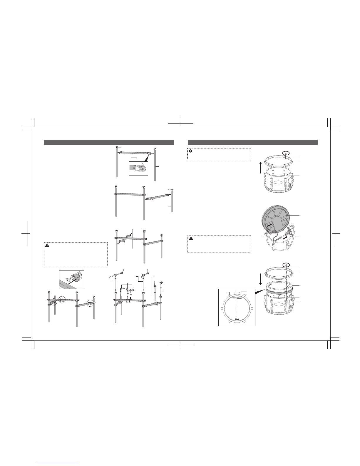
Note
*Remove all components from the Pipe Clamps and Pipe
Brackets before making adjustments to the height of the
rackor position of the Pipe Clamps.
*Securely tighten (don’t over-tighten) all handle bolts on the
Pipe Clamps and Pipe Brackets when the positions are
finalized.
1. Locate the two “long” legs (each has a PCL-100 Pipe
Bracket attached) and connect one to each end of the
Front Bar (it has a Pearl logo badge) as shown (Fig. 1).
Orient the Front Bar so that the “Pearl” logo on the
clamps is facing right-side up for optimum stability
(Fig. 1-A).
2. Connect a Side Bar to the left “long” leg as shown (Fig.
2) with the “Pearl” logo on the clamps facing right-side
up for optimum stability (Fig.1-A). Locate the “short”
leg with a PCL-100 Pipe Bracket attached and connect
it to the other end of the Side Bar as shown.
3. Connect the last Side Bar to the right “long” leg as
shown (Fig. 3) with the “Pearl” logo on the clamps
facing right-side up for optimum stability (Fig. 1-A).
Connect the remaining “short” leg to the other end of
the Side Bar as shown.
4. Adjust the height of the Front and Side Bars to your
preference and make sure that all bars are levelled.
5. Attach two Pipe Clamps to the Front Bar and one each
on both Side Bars (Fig. 4 and 4-A).
6. Attach the Tom Holders, Cymbal Holders, Hi-Hat
Holder and the Universal Clamp to the Pipe Clamps
and Pipe Bracket as shown below (Fig. 5).
7. Reverse the position of the left and right Side Bars if
you’re left-handed.
Caution
Caution
ASSEMBLYING THE TOMS AND SNARE DRUM
*The bottom head on the Toms and the snare side head on
the Snare Drum are pre-assembled at the factory.
*Tighten the Tension Bolts with only enough tension to hold
the Hoop in place. Using greater tension can damage the
plastic frame of the Tru-trac Drumheads and void the
warranty.
1. Loosen the Tension Bolts on the batter side of the
drums using the provided Drum Key and remove the
Hoops (Fig. 6).
2. Locate the Tru-trac Drumhead that corresponds to the
diameter of each drum. NOTE: The two 14” Tru-trac
Drumhead are identical and either can be used on the
14” Tom or the Snare Drum.
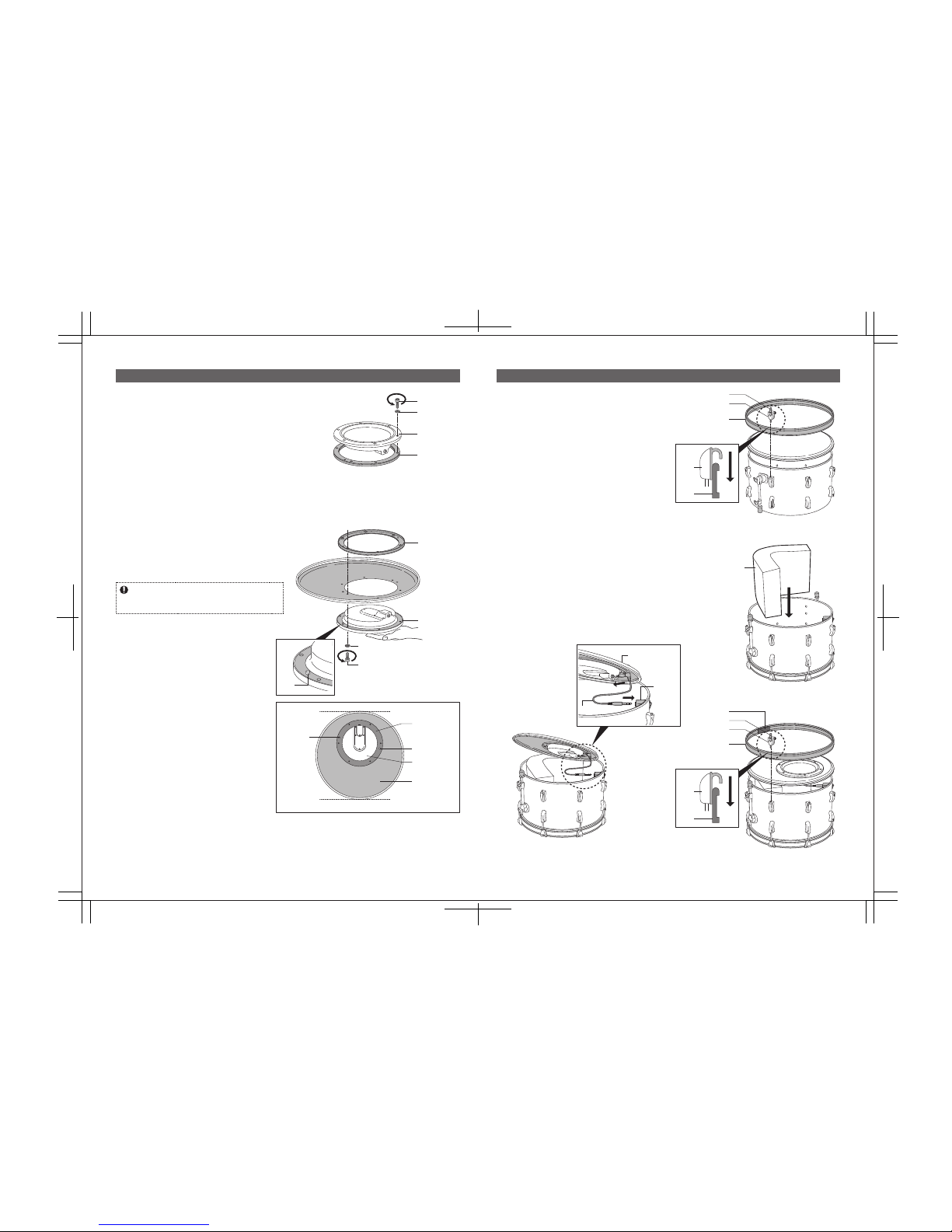
3. Insert the “L” shaped end of the Jack Box Cable into
the Jack on the underside of the Tru-trac Drumhead
(Fig. 7).
4. Insert the other end of the Jack Box Cable into the
Jack Box inside the shell (Fig. 7).
5. Place the Tru-Trac Drumhead on the shell and reattach
the Hoop with the Tension Bolts (Fig. 8). NOTE: The
Jack Box Cables are short and have only limited reach.
When assembling Toms, align the Tru-Trac logo with
the BT-70 Tom Holder Bracket as shown (Fig. 8-A).
Similarly, when assembling the Snare Drum, align the
Tru-Trac logo with the E-Pro Live Badge.
Long Leg
PCL-100 Pipe Bracket
PCL-100
Pipe Bracket
Short Leg
Fig.1
Fig.1-A
Fig.6
Fig.7
Fig.8
Fig.8-A
Fig.2
Fig.3
Fig.5Fig.4
Fig.4-A
Tesion Bolt
Hoop
Tru-trac Drumhead
Tru-trac Drumhead
Jack Box
Jack Box
Cable
Lug
Tension Bolt
Universal
Clamp
Hi-Hat Holder
Cymbal Holder
Cymbal Holder
Tom Holders
Hoop
BT-70
BT-70
Lug
Lug
Bar
sample