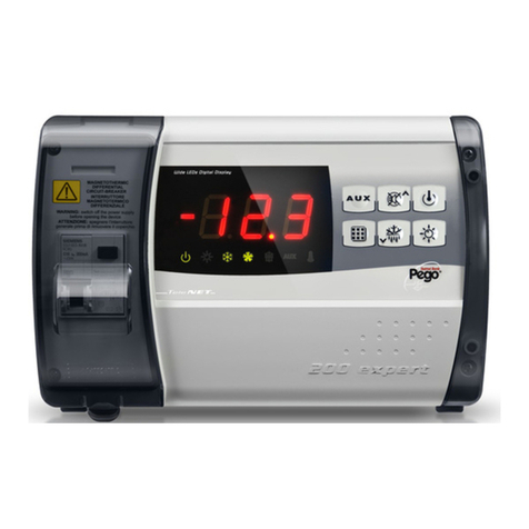
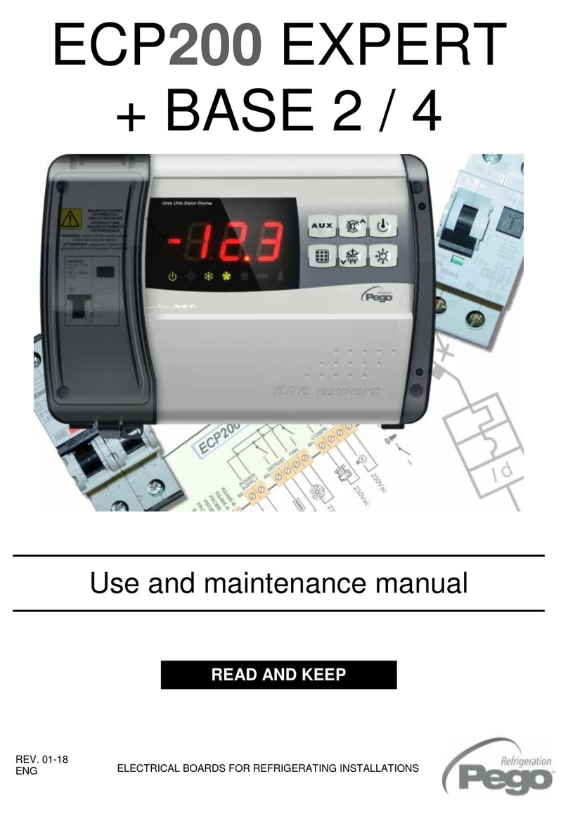
Pego PLUS 200 2 PLT User manual

PLUS 200 2 PLT
rev 02-06

PLUS 200 2 PLT
Page 2 Rev. 02-06
MANUALE D’USO E MANUTENZIONE

PLUS 200 2 PLT
Page 3
Rev. 02-06 MANUALE D’USO E MANUTENZIONE
INTRODUCTION
Page 4 1.1 General
Page 4 1.2 Product ID codes
Page 5 1.3 Overall dimensions
Page 5 1.4 Identification data
INSTALLATION
Page 6 2.1 Important information for installer
Page 6 2.2 Standard assembly and use kit
FUNCTIONS
Page 7 3.1 Functions managed by the Plus 200 2 PLT
TECHNICAL CHARACTERISTICS
Page 8 4.1. Technical characteristics
Page 9 4.2 Warranty terms
PARAMETER PROGRAMMING
Page 10 5.1 Panel layout
Page 11 5.2 Keypad functions
Page 12 5.3 LCD display
Page 13 5.4 General
Page 13 5.5 Key to symbols
Page 13 5.6 Setting and displaying the set-points
Page 14 5.7 Level 1 programming
Page 15 5.8 List of Level 1 variables
Page 16 5.9 Level 2 programming
Page 17 5.10 List of Level 2 variables
Page 19 5.11 Switching on the PLUS 200 2 PLT electronic controller
Page 19 5.12 Compressor activation/deactivation conditions
Page 19 5.13 Configurations
Page 19 5.14 Single set-point with double system
Page 19 5.15 Double set point
Page 20 5.16 Manual defrosting
Page 20 5.17 Hot gas defrosting
Page 20 5.18 Changing the date / time settings
TROUBLESHOOTING
Page 21 6.1 Troubleshooting guide
APPENDICES
Page 23 A.1 EC declaration of conformity
Page 24 A.1 PLUS200 2 PLT connection diagram
CONTENTS
CHAP. 1
CHAP. 5
CHAP. 6
CHAP. 2
CHAP. 3
CHAP. 4

PLUS 200 2 PLT
Page 4 Rev. 02-06
MANUALE D’USO E MANUTENZIONE
GENERAL
The electronic controllers of the PLUS 200 series have been designed to control static or
ventilated cold rooms.
The PLUS200 2 PLT electronic panel allows the user to control all the components on a
refrigeration unit equipped with a double system. The panel allows the user to control the
essential components of a refrigeration system with up to two compressors, a double
evaporator (fans and defrosting elements) and a cold room light.
The double evaporator is controlled separately with a double defrosting sensor.
PRODUCT IDENTIFICATION CODES
PLUS200 2 PLT Controller for cold rooms with double
storage system.
1.1
1.2
CHAPTER 1: INTRODUZIONE
CHAP. 1 - Introduction

PLUS 200 2 PLT
Page 5
Rev. 02-06 MANUALE D’USO E MANUTENZIONE
OVERALL DIMENSIONS
IDENTIFICATION DATA
The unit described in this manual has, on its side, an ID plate showing all the relevant
identification data:
• Name of Manufacturer
• Code and model of electrical board
• Serial number
• IP protection rating
• Power supply voltage
1.3
1.4
CHAP. 1 - Introduction

PLUS 200 2 PLT
Page 6 Rev. 02-06
MANUALE D’USO E MANUTENZIONE
IMPORTANT INFORMATION FOR THE INSTALLER
1. Install the device in places where the protection rating is observed and try not to
damage the box when drilling holes for wire/pipe seats.
2. Do not use multi-polar cables in which there are wires connected to inductive/power
loads or signalling wires (e.g. probes/sensors and digital inputs).
3. Do not fit power supply wiring and signal wiring (probes/sensors and digital inputs) in
the same raceways or ducts.
4. Minimise the length of connector wires so that wiring does not twist into a spiral shape
as this could have negative effects on the electronics.
5. Fit a general protection fuse upstream from the electronic controller.
6. All wiring must be of a cross-section suitable for relevant power levels.
7. When it is necessary to make a probe/sensor extension, the wires must be of the
correct cross-section, which in any case must be at least 1 mm2.
STANDARD ASSEMBLY AND USE KIT
The PLUS 200 2 PLT electronic controller is supplied with the following assembly and
utilisation items:
•N°3 sealing gaskets to be placed between fixing screws and box backing
•N°3 NTC temperature sensors (room, evaporator 1, evaporator 2)
•N°1 user’s manual.
CHAPTER 2: INSTALLATION
CHAP. 2 - Installation
2.1
2.2

PLUS 200 2 PLT
Page 7
Rev. 02-06 MANUALE D’USO E MANUTENZIONE
FUNCTIONS CONTROLLED BY THE PLUS200 2 PLT
-Display and adjustment of room temperature
-Display of evaporator 1 and evaporator 2 temperature
-System control activation/deactivation
-Operation with single set-point and control of two motor condensing units with delays
between the two parameter-set starts.
-Compressor rotation (to make wear uniform)
-Operation with double set point for gradual application of refrigerating power
-System warnings (temperature sensor error, min-max temperature alarms, compressor
1 and compressor 2 safety devices)
-Evaporator 1 and evaporator 2 fan control
-Automatic/manual defrost control (static, with elements, cycle inversion)
-Clock for real time clock defrosting of the two evaporators simultaneously or separately
(even where defrosting cycle is set simultaneously the end-of-defrost temperature and
control of fan start delay on the two evaporators are independent)
-Room light can be switched on with on-panel key or door switch
-Alarm relay
CHAP. 3 - Functions
CHAPTER 3: FUNCTIONS
3.1

PLUS 200 2 PLT
Page 8 Rev. 02-06
MANUALE D’USO E MANUTENZIONE
TECHNICAL CHARACTERISTICS
Power supply
Voltage 230 V~ ±10% 50 Hz
Max. power absorption ~ 7 VA
Climatic conditions
Working temperature -10 - 60°C
Storage temperature -30 - 70°C
Relative humidity Below 90% RH
General characteristics
Type of sensors that can be connected NTC 10K 1%
Resolution 1°C
Sensor read precision ± 0.5°C
Read range -45…+45 °C
PLUS200 2 PLT - Output characteristics - max applicable load (230 V AC)
Compressor (non-powered contact) 750W (AC3)
Elements (non-powered contact) 1500W (AC1)
Fans (non-powered contact) 500W (AC3)
Room light (non-powered contact) 800W (AC1)
Alarm contact 800W (AC1)
Dimensional characteristics
Dimensions 19.3 cm x 7.9 cm x 20.3 cm (HxPxL)
Insulation / mechanical characteristics
Box protection rating IP65
Box material ABS self-extinguishing
Type of insulation Class II
CHAP. 4 – Technical characteristics
CHAPTER 4: TECHNICAL CHARACTERISTICS
4.1

PLUS 200 2 PLT
Page 9
Rev. 02-06 MANUALE D’USO E MANUTENZIONE
WARRANTY TERMS
PLUS200 electronic controllers are covered by a 24-month warranty against all
manufacturing defects, valid from date of delivery. If the system malfunctions as a result of
tampering, impact or improper installation the warranty will automatically be rendered null
and void. It is strongly recommended that you observe all instructions/information
regarding the technical characteristics of the device.
WARNING !
Any modifications made to wiring and/or internal components or any tasks
carried out in a way that fails to comply with the information/instructions in this
manual shall not only render the warranty null and void immediately but may
also lead to malfunctions, irreparable damage, serious injury or put
persons/objects in danger.
PEGO S.r.l. declines any responsibility for possible errors or inaccuracies
written in this manual as a result of printing or transcription errors.
PEGO S.r.l. reserves the right to modify its products as it deems necessary
without altering its main characteristics. Each new release of a PEGO user
manual replaces previous ones.
4.2
CHAP. 4 – Technical characteristics
)

PLUS 200 2 PLT
Page 10 Rev. 02-06
MANUALE D’USO E MANUTENZIONE
PANEL LAYOUT
1. Display of current month (previous months also remain lit)
CHAP. 5 - Parameter programming
CHAPTER 5: PARAMETER PROGRAMMING
5.1
n

PLUS 200 2 PLT
Page 11
Rev. 02-06 MANUALE D’USO E MANUTENZIONE
KEYPAD FUNCTIONS
1. CLOCK DISPLAY key (press key to display current time for a few seconds)
2. UP / MUTE BUZZER ALARM key
3. STAND BY key (system shuts down, room temperature flashes)
4. SET key, room temperature (with double set point both are shown
alternately)
5. DOWN / MANUAL DEFROST key
6. ROOM LIGHT key
CHAP. 5 - Parameter programming
5.2
n p
q r s
o

PLUS 200 2 PLT
Page 12 Rev. 02-06
MANUALE D’USO E MANUTENZIONE
DISPLAY LCD
1. Ambient temperature / parameters
2. Evaporator 1 temperature / Evaporator 2 temperature / day of current month (see
setting on parameter tEu on 1st level programming) / parameters (during
programming)
3. System status / time / parameter values:
a. C1 = compressor 1 active
b. C2 = compressor 2 active
c. d1 = evaporator 1 defrosting
d. d2 = evaporator 2 defrosting
e. Current time
f. Time parameters
4. Programming (control is in programming mode)
5. Cold (compressor call indicator)
6. Defrost
7. Fans (flashing during fan stop – parameter F5)
8. Light
9. Alarm
10.Stand-by (flashing in stand-by. Outputs deactivated.)
CHAP. 5 - Parameter programming
5.3
n
p
qrs
o
t u v w

PLUS 200 2 PLT
Page 13
Rev. 02-06 MANUALE D’USO E MANUTENZIONE
GENERAL
To enhance safety and simplify the operator’s work, the PLUS 200 system has two
programming levels; the first level (Level 1) is used to configure the frequently-modified
SET-POINT parameters. The second programming level (Level 2) is for general parameter
programming of the various controller work modes.
It is not possible to access Level 2 programming directly from Level 1: you must exit the
programming mode first.
KEY TO SYMBOLS
For purposes of practicality the following symbols are used::
• (t)the UP key is used to increase values and mute the buzzer;
• (u)the DOWN key is used to decrease values and force defrosting.
SETTING AND DISPLAYING THE SET-POINTS
1. Press the SET key to display the current SET-POINT (temperature).
2. Hold down the SET key and press the (t) or (u) keys to modify the SET-POINT.
3. Release the SET key to return to room temperature display: the new setting will be
saved automatically.
Note: with the double set point configuration the display of the two set points is alternated
each time SET is pressed.
5.4
CHAP. 5 - Parameter programming
5.5
5.6

PLUS 200 2 PLT
Page 14 Rev. 02-06
MANUALE D’USO E MANUTENZIONE
LEVEL 1 PROGRAMMING (User level)
To gain access to the Level 1 configuration menu proceed as follows:
1. Press the (t) and (u)keys simultaneously and keep them pressed for a few seconds
until the first programming variable appears on the display.
2. Release the (t) and (u)keys.
3. Select the variable to be modified using the (t) or (u) key.
4. When the variable has been selected it is possible:
• to display the setting by pressing SET
• to modify the setting by pressing the SET key and the (t) or (u)keys.
When configuration values have been set you can exit the menu by pressing the (t) and
(u)keys simultaneously for a few seconds until the cold room temperature reappears.
5. The new settings are saved automatically when you exit the configuration menu.
CHAP. 5 - Parameter programming

PLUS 200 2 PLT
Page 15
Rev. 02-06 MANUALE D’USO E MANUTENZIONE
LIST OF LEVEL 1 VARIABLES (User level)
VARIABLE MEANING VALUES DEFAULT
r0 Temperature differential referred to main SETPOINT (both
set points where double) 1 - 10 °C 2°C
d0
Defrost interval (hours). In the case of the double evaporator
defrost start is simultaneous and time d0 is reloaded at the end
of the last defrost
0 - 24 hrs 4 hrs
d21
End-of-defrost set point, evaporator 1.
Defrost is not executed if the temperature read by the defrost
sensor is greater than value d21
(If the sensor is faulty defrosting is time-based)
-35 - 45 °C
15°C
d22
End-of-defrost set point, evaporator 2.
Defrost is not executed if the temperature read by the defrost
sensor is greater than value d22
(If the sensor is faulty defrosting is time-based)
-35 - 45 °C 15°C
d31 Maximum defrost duration, evaporator 1 (minutes) 1 - 120 min 25 min
d32 Maximum defrost duration, evaporator 2 (minutes) 1 - 120 min 25 min
d7
Drip duration (minutes)
At the end of defrosting the compressor and the fans remain at
standstill for time setting d7: the defrost LED on the front of the
panel flashes.
0 - 120 min
0 min
F5
Fan pause after defrost (minutes)
Allows fans to be kept at standstill for a time F5 after dripping.
This time is counted from the end of dripping. If dripping is not
set the fan pause is executed directly after the end of
defrosting. During the pause the fan icon flashes.
0 - 10 min
0 min
dEL Second system start delay (valid if nrC=2) 0-60 min 30 min
A1
Minimum temperature alarm
(active only during storage)
Allows user to define a minimum cold room storage
temperature. Below the value A1 a warning is given: the alarm
LED and the displayed temperature flash and the fault is also
highlighted by an internal buzzer.
- -45°C
A2
Maximum temperature alarm
(active only during storage).
Allows user to define a maximum cold room storage
temperature. Above the value A2 a warning is given: the alarm
LED and the displayed temperature flash and the fault is also
highlighted by an internal buzzer.
- +45°C
5.8
CHAP. 5 - Parameter programming

PLUS 200 2 PLT
Page 16 Rev. 02-06
MANUALE D’USO E MANUTENZIONE
LEVEL 2 PROGRAMMING (Installer level)
To access the second programming level press the UP (t) and DOWN (u)keys and the
LIGHT key simultaneously for a few seconds.
When the first programming variable appears the system automatically goes to stand-by.
1. Select the variable to be modified by pressing the UP (t) and DOWN (u)keys.
When the parameter has been selected it is possible to:
2. View the setting by pressing the SET key.
3. Modify the setting by holding the SET key down and pressing the (t) or (u)key.
VARIABLE MEANING VALUES DEFAULT
tEu Displays evaporator sensor temperature / current
day-date
0 = current day
1 = displays
evaporator 1
temperature;
displays nothing if
dE =1
2 = displays
evaporator 2
temperature;
displays nothing if
dE2 =1
0
dF1
Real-time defrost enable, evaporator 1
With dF1=1 it is possible to set up to 6 defrosts in real
time in a day by using the parameters d41…d46
0 disabled
1 enabled 0
dF2
Real-time defrost enable, evaporator 2
With dF2=1 it is possible to set up to 6 defrosts in real
time in a day by using the parameters d51…d56
0 disabled
1 enabled 0
d41…d46
Programming defrost times, evaporator 1
It is possible to set up to 6 defrosting times
00:00:00 -
23:50:00 --
d51…d56
Programming defrost times, evaporator 2
It is possible to set up to 6 defrosting times
00:00:00 -
23:50:00 --
CHAP. 5 - Parameter programming
5.9

PLUS 200 2 PLT
Page 17
Rev. 02-06 MANUALE D’USO E MANUTENZIONE
4. When configuration settings have been completed you can exit the menu by pressing
the (t) and (u)keys simultaneously and keeping them pressed until the room
temperature value reappears.
5. Changes are saved automatically when you exit the configuration menu.
6. Press the STAND-BY key to enable electronic control.
LIST OF LEVEL 2 VARIABLES (Installer level)
VARIABLE MEANING VALUES DEFAULT
nrC Number of compressors (or solenoids
or systems)
1= 1 system
2= 2 systems 2
nrE Number of evaporators 1= 1 evaporator
2= 2 evaporators 2
SEt Single or double set-point setting
Only displayed if nrC=2
0= one setting only
1= double setting 0
rot Compressor rotation 0= compressor rotation
1= fixed call 0
AC Microswitch input status 0= normally open
1= normally closed 0
F3 Fan status with compressor off
0 = Fans running continuously
1 = Fans running only if
compressor is working
1
F4 Fan pause during defrost
0 = Fans running during
defrost
1 = Fans not working during
defrost
1
dE1
Evaporator 1 sensor presence
Disabling the evaporator sensor causes
defrosts to occur cyclically with period d0
or by real time clock and terminate
according to time d31
0 = evaporator 1 sensor
present
1 = evaporator 1 sensor
absent
0
dE2
Evaporator 2 sensor presence
Disabling the evaporator sensor causes
defrosts to occur cyclically with period d0
or by real time clock and terminate
according to time d32
0 = evaporator 2 sensor
present
1 = evaporator 2 sensor
absent
0
dC Man in cold room alarm input status 0 = NO
1 = NC 0 = NA
d1
Defrost type, cycle inversion (hot gas) or
elements
With 2 compressors and only 1 evaporator
both compressors are activated
1= hot gas
0= element 0
d8
Post-defrost compressor start mode.
Determines whether system compressor
start is possible or not if second is
defrosting
0= if an evaporator is still
defrosting the second system
can continue working
1= compressors do not start
until all defrosts have been
completed
0
5.10

PLUS 200 2 PLT
Page 18 Rev. 02-06
MANUALE D’USO E MANUTENZIONE
Ad Network address for connection to the
TeleWIN supervision system 0 – 31 0
Ald Minimum and maximum temperature
signalling and alarm display delay 1…240 min 2:00:00
C1
Minimum time between shutdown and
subsequent switching on of the
compressor.
0…15 min 0 min
Hr1
Compressor 1 hour counter (can be
reset by pressing the set and clock keys
for 10 sec)
0-999 tens of hours 0
Hr2
Compressor 2 hour counter (can be
reset by pressing the set and clock keys
for 10 sec)
0-999 tens of hours 0
CAL Room sensor value correction -10…+10 0
Pc1 Compressor 1 protection contact status 0 = NO
1 = NC 0 = NA
Pc2 Compressor 2 protection contact status 0 = NO
1 = NC 0 = NA
doC
Compressor safety time for door
switch: when the door is opened the
evaporator fans shut down and the
compressor will continue working for time
doC, after which it will shut down.
0…5 minutes 0
Fst
FAN shutdown TEMPERATURE
The fans will stop if the temperature value
read by the evaporator sensor is higher
than this value.
-45…+45°C +45°C
tA NO – NC alarm relay switching
=activates when alarm is on
1=deactivates when alarm is
on
1
rA Control relay door anti-fogging element 0=alarm relay
1=anti-fogging element on 0
int Spare ------ --
dMY Day-month-year setting dd-mm-yy -
hMS Clock setting Hour-min-sec -
CHAP. 5 - Parameter programming

PLUS 200 2 PLT
Page 19
Rev. 02-06 MANUALE D’USO E MANUTENZIONE
SWITCHING ON THE PLUS 200 PLT ELECTRONIC CONTROLLER
After wiring the controller correctly, power up at 230 V AC; the panel will immediately emit
a beep and all segments and LEDs come on simultaneously for a few seconds.
COMPRESSOR ACTIVATION/DEACTIVATION CONDITIONS
The PLUS 200 controller activates the compressor when cold room temperature exceeds
setting+differential (r0); it deactivates the compressor when cold room temperature is
lower than the setting.
CONFIGURATIONS
-Control of 2 motor condenser units with 2 evaporators
-Control of 1 motor condenser unit with 2 evaporators
-Control of unit panel with 2 evaporators
-Control of 2 motor condenser units with 1 evaporator
Functional combinations are managed by nrC (number of compressors) and nrE (number
of evaporators) parameters.
SINGLE SET POINT WITH DOUBLE SYSTEM
With a single set point (parameter SEt=0) and double system (parameter nrC=2).
The controller initially ‘calls’ the compressor which has worked less if rot=0 or calls
compressor 1 and then 2 after the delay if rot=1. If the set point is not reached within time
DeL (1st level parameter) the second presser is switched on to help.
DOUBLE SET POINT
With SEt=1 (double set), there are 2 distinct set points for the 2 compressors. Setting of
the 2 set points is done by pressing the set key: press once and the set value will appear
with St1 alongside; the second time it is pressed the second set value and appears with
St2 alongside.
If rot=0 there will be compressor rotation (with reference to the lowest set point the
compressor that has worked the least will be started)
5.11
5.12
5.13
CHAP. 5 - Parameter programming
5.14
5.15

PLUS 200 2 PLT
Page 20 Rev. 02-06
MANUALE D’USO E MANUTENZIONE
MANUAL DEFROSTING
To defrost just press the dedicated key (see section 5.2) to activate the elements relay.
Defrosting will not take place if the end-of-defrost temperature setting (d21 or d22) is lower
than the temperature detected by the evaporator sensor. Defrosting ends when the end-of-
defrost temperature (d21 or d22) or maximum defrost time (d31 or d32) is reached.
Manual defrosting is possible even if real time clock defrosting is set.
HOT GAS DEFROSTING
Set parameter d1 =1 to manage defrost in cycle inversion mode.
The compressor relay and defrost relay are activated throughout the defrost phase. During
dripping (d7) the compressor shuts down but the defrost relay remains activated.
To ensure proper control of the system the installer must use the defrost output: this must
allow opening of the cycle inversion solenoid valve and closure of the liquid solenoid valve.
For capillary systems (without thermostat valve) it is only necessary to control the cycle
inversion solenoid valve via the defrost relay control.
MODIFYING DATE AND TIME
To change date and time settings just modify the values as per the parameter setting
procedure described in section 5.9 of this manual.
CHAP. 5 - Parameter programming
5.16
5.17
5.18
Table of contents
Other Pego Controllers manuals

Pego
Pego ECP200 BASE Series User manual

Pego
Pego ECP200 Expert d7.5 User manual

Pego
Pego EasySteam 400HUM2ESXX User manual

Pego
Pego Vision Touch Wellness Operating instructions
Pego
Pego PLUS 100 THR User manual

Pego
Pego VISION TOUCH THR Operating instructions

Pego
Pego VISION SC600 User manual

Pego
Pego PLUS 100 AB User manual

Pego
Pego 200PEVS01 Operating instructions
Pego
Pego ECP200 Expert d7.5 User manual