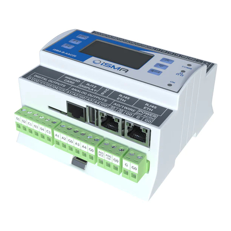
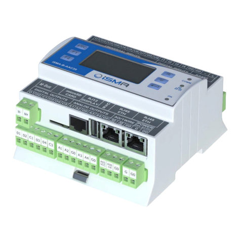
iSMA iSMA-B-AAC20 User manual

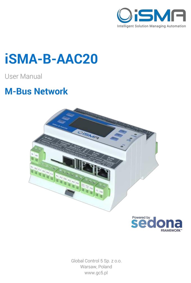
iSMA-B-AAC20
User Manual
Sedona Modbus
Global Control 5 Sp. z o.o.
Warsaw, Poland
www.gc5.pl

iSMA-B-AAC20/Sedona Modbus
Version 1.3 www.gc5.pl Page 2/ 55
Table of contents
1Introduction............................................................................................................................... 4
1.1 Revision history ................................................................................................................ 4
2Sedona Modbus....................................................................................................................... 4
3Installing iSMA Modbus kits.................................................................................................. 7
4Modbus Async Network kit.................................................................................................... 8
4.1 Modbus Async license and limitation .......................................................................... 8
4.2 Modbus Async Network.................................................................................................. 8
4.3 Modbus Async Device...................................................................................................11
4.4 Modbus data points....................................................................................................... 13
4.4.1 Modbus Async Boolean Point .........................................................................13
4.4.2 Modbus Async Boolean Writable.................................................................... 14
4.4.3 Modbus Async Numeric Point.........................................................................16
4.4.4 Modbus Async Numeric Writable ...................................................................17
4.4.5 Modbus Async Numeric Multi Point .............................................................. 19
4.5 Modbus folder.................................................................................................................20
5Modbus TCP Network kit .....................................................................................................21
5.1 Modbus TCP license and limitation............................................................................21
5.2 Modbus TCP Network ...................................................................................................21
5.3 Modbus TCP Device.......................................................................................................23
5.4 Modbus TCP data points ..............................................................................................25
5.4.1 Modbus TCP Boolean Point .............................................................................25
5.4.2 Modbus TCP Boolean Writable .......................................................................27
5.4.3 Modbus TCP Numeric Point ............................................................................28
5.4.4 Modbus TCP Numeric Writable.......................................................................30
5.4.5 Modbus TCP Numeric Multi Point..................................................................31
5.5 Modbus folder.................................................................................................................33
6Modbus TCP Slave Network kit (IP Module) ....................................................................34
6.1 Modbus TCP Slave Network ........................................................................................35
6.2 Modbus TCP Slave data points ...................................................................................35
6.2.1 Boolean Value.....................................................................................................36
6.2.2 Numeric Value ....................................................................................................37
6.3 Modbus Folder................................................................................................................39
6.4 Modbus RS 485 Slave Device (COM1) .......................................................................40
6.4.1 Modbus Slave COM1 wiring.............................................................................40
7Gateway mode .......................................................................................................................42
8iSMA Module...........................................................................................................................43
8.1 iSMA Device.....................................................................................................................44
8.2 iSMA Device config component ..................................................................................44
8.3 iSMA IO components.....................................................................................................45
8.3.1 DI components ...................................................................................................45

iSMA-B-AAC20/Sedona Modbus
Version 1.3 www.gc5.pl Page 3/ 55
8.3.2 DO components ................................................................................................. 46
8.3.3 UI components ...................................................................................................47
8.3.4 AO components..................................................................................................48
8.3.5 iSMA Folder......................................................................................................... 49
9iSMA-B-AAC20 Modbus table..............................................................................................50

iSMA-B-AAC20/Sedona Modbus
Version 1.3 www.gc5.pl Page 4/ 55
1Introduction
This manual contains information about Modbus protocols in iSMA-B-AAC20 controller.
The iSMA-B-AAC20 controller support following types of Modbus:
•Modbus ASCII/RTU
•Modbud TCP
•Modbus TCP Slave
1.1Revision history
Rev
Date
Description
1.0
28.08.2015
•First edition
1.3
20.04.2017
•Added Modbus type of registers addressing in Modbus TCP Slave
•Added information about accuracy increasing and Resistance
Register multiply in PT1000 or NI1000 input working type
2Sedona Modbus
The Modbus protocol defines a message structure and format used in communication
transactions. Modbus devices communicate using a master-slave method, in which only the
master device can initiate a communications transaction. There can be only one master
device on a Modbus network. All other devices must be Modbus Slaves.
WARNING! Before programming Modbus kits, please check if the latest kit version is used.
The latest kits are available on GC5 support website: www.support.gc5.pl
Modbus registers
A Modbus device holds transient (real-time) data and often persistent (configuration) data in
addressable registers. Here, the term “registers” implies all addressable data, but this is a loose
interpretation. Using Modbus nomenclature, all accessible data in a Modbus Slave is
contained in the following four available groups of data flags and registers (including the
Modbus Master access that is possible):

iSMA-B-AAC20/Sedona Modbus
Version 1.3 www.gc5.pl Page 5/ 55
Coil status - Or simply “coils”: single-bit flags that represent the status of Digital (Boolean)
Outputs of the slave, that is, On/Off output status. A Modbus Master can both read from
and write to coils.
Input status - Or simply “inputs”: single-bit flags that represent the status of Digital (Boolean)
Inputs of the slave, that is, On/Off output status. A Modbus Master can read (only) inputs.
Input register - Are 16-bit registers that store data collected from the field by the Modbus
Slave. The Modbus Master can read (only) input registers.
Holding register - Are 16-bit registers that store general-purpose data in the Modbus Slave.
The Modbus Master can both read from and write to input registers.

iSMA-B-AAC20/Sedona Modbus
Version 1.3 www.gc5.pl Page 6/ 55
Modbus data addresses
A Modbus device is not required to contain all four groups of data. For example, a metering
device may contain only holding registers. However, for each data group implemented, an
“address convention” is used. The requests for data (made to a device) must specify a data
address (and range) of interest.
Modbus data in a device is addressed as follows:
Coils —Addressed at 00000 —0nnnn decimal, or “0x” addresses,
Inputs —Addressed at 10000 —1nnnn decimal, or “1x” addresses,
Input Registers—Addressed at 30000 —3nnnn decimal, or “3x” addresses,
Holding Registers —Addressed at 40000 —4nnnn decimal, or “4x” addresses.
Note: the data addressing (at least in decimal and hex formats) is zero-based, where the first
instance of a data item, for example coil 1, is addressed as item number 0. As another
example, holding register 108 is addressed as 107 decimal or 006B hex.

iSMA-B-AAC20/Sedona Modbus
Version 1.3 www.gc5.pl Page 7/ 55
3Installing iSMA Modbus kits
There are 4 Modbus kits in iSMA-B-AAC20 controller:
iSMA Modbus Async Network - to serve Modbus RS485 Master port of the iSMA-B-AAC20
controller,
iSMA Modules - extension of Modbus Async Netwok to serve iSMA MIX, Wireless and MINI
devices using Modbus Async protocol,
iSMA Modbus TCP Network - to serve Modbus TCP Master of the iSMA-B-AAC20 device using
IP connection,
iSMA Modbus TCP Slave Network - to serve Modbus TCP Slave of the iSMA-B-AAC20
controller using IP connection.
To install Modbus kits, import the kits to the WorkPlace software (possibly as part of the
package of various kits in a zip file). To do this, use an application from the Tools menu ->
Sedona Installer.
After successful import of the files, upload the files to your device using the Kit Manager
Application from the Sedona Tools package.
WARNING! Before programming Modbus Network, please check if the latest kit version is
used. The latest kits are available on GC5 support website: www.support.gc5.pl
Figure 1 –Sedona Installer

iSMA-B-AAC20/Sedona Modbus
Version 1.3 www.gc5.pl Page 8/ 55
4Modbus Async Network kit
This section provides a collection of procedures to use the iSMA-B-AAC20 Modbus drivers to
build networks of devices with Modbus points. The iSMA-B-AAC20 controller has one RS485
port which can be used as a Modbus RTU / ASCII Master.
Modbus Async Network kit consists of 4 types of components:
Modbus Network,
Modbus Device,
Modbus Data Points,
Modbus Points folder.
4.1 Modbus Async license and limitation
In standard license, there are available 500 data points and this number cannot be expanded.
Number of available points is shown in ModbusAsyncNetwork component in slot Free Points.
WARNING! Each device and data point is counted as one point. For example to read 7 data
points from 15 devices: Points number = 15 *(1 + 7) = 105
4.2 Modbus Async Network
Modbus Network is a main component which is responsible for servicing RS485 COM2
physical port. The component must be placed under Drivers folder. Modbus Network sets
parameters such as communication baud rate and data format, testing etc. and keeps
statistic.
The component has the following actions available under the right mouse button:
Reset Statistic –Reset network statistic value and stat counting from the beginning,
Enable/Disable –switch on/off Modbus Network.

iSMA-B-AAC20/Sedona Modbus
Version 1.3 www.gc5.pl Page 9/ 55
Figure 2 –Modbus Async Network component
Modbus Async Network component has the following slots:
Status –Network status, available states:
OK –Network is working properly,
Disabled –Network is disable (Slot “Enable” is in false),
OK some device/point down –error in device or points.
Fault Cause –Fault cause description,
Enable –this option switch on or switch off Modbus Network
(„true”- Network enable, „false”- Network disable),
Steady Time –Network start up delay time after power up or reset,
Baud Rate –Modbus RS485 port baud rate, available options:
2400, 4800, 9600, 19200, 38400, 57600, 115200 bps,
Stop Bits –Stop bit definition, available options: 1-bit, 2-bits,
Data Bits –Data bits definition, available options: 7-bits or 8-bits,
Parity –Parity bit definition, available options: None, Odd, Even, Always1, Always0,
Modbus Type –Modbus type definition , available options: RTU or ASCII,
Ping Enable –Enable devices connection testing function,
Ping Frequency –Time between testing message to check device connection,
Down Frequency –Time between testing message for devices or points which have got
status down,

iSMA-B-AAC20/Sedona Modbus
Version 1.3 www.gc5.pl Page 10 / 55
Write On Start –Do write action in device „Writable” components in Modbus Network after
reset or power up,
Write On Up - Do write action in device „Writable” components in Modbus Network after
restore the connection with Modbus device,
Write On Enable - Do write action in device „Writable” components in Modbus Network after
enable the device,
Fast Rate –Time between messages in „Fast” mode poll frequency,
Normal Rate –Time between messages in „Normal” mode poll frequency,
Slow Rate –Time between messages in „Slow” mode poll frequency,
Average Poll Time –Average time for sending/receive one message,
Busy Time –Percentage of Modbus Network usage,
Total Polls –Total number of messages,
Fast Polls –Number of messages in sending „Fast” mode,
Normal Polls –Number of messages in sending „Normal” mode,
Slow Polls –Number of messages in sending „Slow” mode,
Timeouts –Number of lost messages, difference between sending and receive messages,
Errors –Number of error messages (for example with wrong CRC)
Free points –Number of available physical points in Modbus Network.

iSMA-B-AAC20/Sedona Modbus
Version 1.3 www.gc5.pl Page 11 / 55
4.3 Modbus Async Device
ModbusAsyncDevice is a component which is responsible for servicing physical device
connected to Modbus Network. The device as Modbus Master to all other Modbus devices on
the attached RS485 port. Each device is represented by a Modbus Device, and has a unique
Modbus address (1 to 247), as well as other Modbus config data and starting addresses for
Modbus data items (coils, inputs, input registers, holding registers). The component has Ping
action available under the right mouse button, which sends test message to device to check
device status. Each ModbusAsyncDevice has a “Ping Address” container slot with 3 properties
slots (Address Format, Ping Address Reg, Ping Type). These properties specify a particular
data address (either input register or holding register) to use as the device status test
(meaning “Monitor” ping requests). Ping requests are generated at the network-level by the
configurable network monitor (ModbusNetwork -> Ping Enabled). When enabled, a network’s
monitor periodically pings (queries) this address. While receiving Any response from the
device, including an exception response, this is considered proof of communication, and the
Modbus client device is no longer considered “down” if it had been previously marked “down”.
The component has Ping action available under the right mouse button, which sends test
message to device to check device status.
Figure 3 - Modbus Async Device component

iSMA-B-AAC20/Sedona Modbus
Version 1.3 www.gc5.pl Page 12 / 55
Modbus Async Device has the following slots:
Status –Device actual status (read Only), can take the following states:
OK –Device is working properly,
Disable –Device is disable (Slot “Enable”is in false),
Down –Device is not available,
Ok, some points down/error –error in points reading,
Network disabled –Modbus Network is disabled.
Fault Cause –Fault cause description,
Fault Status –device error status (true –device communication error),
Enable –Enable/Disable device,
Device Address –Modbus device physical address (0 –network broadcast address, 1-248
addressing range),
Timeout –Max. device response time from device request,
Inter Message Delay –Time between messages sending to device,
Retry Count –Max. error messages (CRC error, lost messages),
Address Format –Modbus address format (Modbus, Decimal),
Ping Address Reg –Any register number Input or Holding type, which will be reading for
device connection test,
Ping Type –Tested register type: Input/Holding,
Byte Order –Byte order reading 32-bit: 3210 (Big endian), 1032 (Little endian).

iSMA-B-AAC20/Sedona Modbus
Version 1.3 www.gc5.pl Page 13 / 55
4.4 Modbus data points
In Modbus protocol each device has implemented Modbus table. Sedona has 5 components
to read/write data from this table:
Boolean Point –Read Boolean value (Modbus command 0x02),
Boolean Writable –Read/write Boolean value (Modbus command 0x05),
Numeric Point –Read numeric value (Modbus commands: Input - 0x04, Holding –0x03 ),
Numeric Writable –Read/write numeric value (Modbus commands: 16-bits Int, SInt - 0x06,
32-bits Long, SLong, Float –0x16),
Numeric Multi Point –Read up to 8 16-bits registers (Modbus command 0x16).
4.4.1 Modbus Async Boolean Point
Modbus Async Boolean Point is a component which is responsible for reading Boolean values
from the device. The component has Read action available under the right mouse button,
which forces the reading of the point.
Figure 4 - Modbus Async Boolean Point component
Modbus Async

iSMA-B-AAC20/Sedona Modbus
Version 1.3 www.gc5.pl Page 14 / 55
Boolean Point component has the following slots:
Status –Point status, available states:
OK –Point is working properly,
Disabled –Point is disable (Slot “Enable” is in false),
Down/Timeout –Point is not available,
Device Down –Device is not available,
Wrong address format –incorrect address format according to address format setting slot,
Device disabled - Device is disabled,
Network disabled –Modbus Network is disabled.
Fault Cause –Fault cause description,
Fault Status –point error status (true –point read error),
Enable –Point enable/disable ( „true”- Point enable, „false”- Point disable),
Address Format –Register address format, available options: Modbus, Decimal,
Address –Register address,
Poll Frequency –Reading poll frequency, available options: Fast, Normal, Slow,
Status Type –Type of reading register, available options: Input –0x02, Coil –0x01,
Out –Current value of read registry.
4.4.2 Modbus Async Boolean Writable
Modbus Async Boolean Writable is a component which is responsible for sending and reading
Boolean values from device.
The component has the following actions available under the right mouse button:
Set True/Set False –Write value to slot In and sends it to the device (not active when slot In
has connected link),
Write –send value from slot In to the device,
Read –read value from device and send to slot Out.

iSMA-B-AAC20/Sedona Modbus
Version 1.3 www.gc5.pl Page 15 / 55
Figure 5 - Modbus Async Boolean Writable component
Modbus Async Boolean Writable component has the following slots:
Status –Point status, available states:
OK –Point is working properly,
Disabled –Point is disable (Slot “Enable” is in false),
Down/Timeout –Point is not available,
Device Down –Device is not available,
Wrong address format –Incorrect address format according to address format setting slot,
Device disabled - Device is disabled,
Network disabled –Modbus Network is disabled.
Fault Cause –Fault cause description,
Fault Status –Point error status (true –point read/write error),
Enable –Point enable/disable ( „true”- Point enable, „false”- Point disable),
Address Format –Register address format, available options: Modbus, Decimal,
Address –Register address,
Poll Frequency –Reading poll frequency, available options: Fast, Normal, Slow,
Write Type –Writing mode, available options: COV –only on input change,
COV_PollFrequrency –on input change and periodically, PollFrequrency - only periodically,

iSMA-B-AAC20/Sedona Modbus
Version 1.3 www.gc5.pl Page 16 / 55
Trigger - Remote force sending trigger (on rising edge),
Out –Output slot, current value of read/write registry,
In –Input slot.
4.4.3 Modbus Async Numeric Point
Modbus Async Numeric Point is a component which is responsible for reading numeric values
from the device. The component has Read action available under the right mouse button,
which forces the reading of the point.
Figure 6 –Modbus Async Numeric Point component
Modbus Async Numeric Point component has the following slots:
Status –Point status, available states:
OK –Point is working properly,
Disabled –Point is disable (Slot “Enable” is in false),
Down/Timeout –Point is not available,
Device Down –Device is not available,
Wrong address format –Incorrect address format according to address format setting slot,
Device disabled - Device is disabled,

iSMA-B-AAC20/Sedona Modbus
Version 1.3 www.gc5.pl Page 17 / 55
Network disabled –Modbus Network is disabled.
Fault Cause –Fault cause description,
Fault Status –Point error status (true –point read error),
Enable –Point enable/disable („true”- Point enable, „false”- Point disable),
Address Format –Register address format, available options: Modbus, Decimal,
Address –Register address,
Poll Frequency –Reading poll frequency, available options: Fast, Normal, Slow,
Reg Type –Type of reading register, available options: Input –0x04, Holding –0x03,
Data Type –Reading registry data type, available options: Int –16-bits, Long –32-bits, Float
–32-bits float-point, SInt –16-bits with sing, Slong –32-bits with sing,
Out –Current value of read registry.
4.4.4 Modbus Async Numeric Writable
Modbus Async Numeric Writable is a component which is responsible for sending and reading
numeric values from the device.
The component has the following actions available under the right mouse button:
Set –write value to slot In and sends it to the device,
Write –send value from slot In to device,
Read –read value from device and sends it to slot Out.

iSMA-B-AAC20/Sedona Modbus
Version 1.3 www.gc5.pl Page 18 / 55
Figure 7 - Modbus Async Numeric Writable component
Modbus Async Numeric Writable component has the following slots:
Status –Network status, available states:
OK –Point is working properly,
Disabled –Point is disable (Slot “Enable” is in false),
Down/Timeout –Point is not available,
Device Down –Device is not available,
Wrong address format –Incorrect address format according to address format setting slot,
Device disabled - Device is disabled,
Network disabled –Modbus Network is disabled.
Fault Cause –Fault cause description,
Fault Status –Point error status (true –point read/write error),
Address Format –Register address format, available options: Modbus, Decimal,
Address –Register address,
Data Type –Read/write registry data type, available options: Int –16-bits, Long –32-bits,
Float –32-bits float-point, SInt –16-bits with sing, Slong –32-bits with sing,
Poll Frequency –Reading poll frequency, available options: Fast, Normal, Slow,
Write Type –Writing mode, available options: COV –only on input change,
COV_PollFrequency –on input change and periodically, PollFrequency - only periodically,

iSMA-B-AAC20/Sedona Modbus
Version 1.3 www.gc5.pl Page 19 / 55
Trigger –Remote force sending trigger (on rising edge),
Out –Output slot, current value of device registry,
In –Input slot.
4.4.5 Modbus Async Numeric Multi Point
Modbus Async Numeric Multi Point is a component which is responsible for reading up to 8
16-bits registers from the device in one message. The component use 0x16 Modbus
command. The component has Read action available under the right mouse button, which
forces the reading of the point.
Figure 8 - Modbus Async Numeric Multi Point component

iSMA-B-AAC20/Sedona Modbus
Version 1.3 www.gc5.pl Page 20 / 55
Modbus Async Numeric Multipoint component has the following slots:
Status –Point status, available states:
OK –Point is working properly,
Disabled –Point is disable (Slot “Enable” is in false),
Down/Timeout –Point is not available,
Device Down –Device is not available,
Wrong address format –Incorrect address format according to address format setting slot,
Device disabled - Device is disabled,
Network disabled –Modbus Network is disabled.
Fault Cause –Fault cause description,
Fault Status –Point error status (true –point read error),
Enable –Point enable/disable („true”- Point enable, „false”- Point disable),
Address Format –Register address format, available options: Modbus, Decimal,
Address –Register address,
Poll Frequency –Reading poll frequency, available options: Fast, Normal, Slow,
Reg Type –Type of reading register, available options: Input –0x04, Holding –0x03,
Data Type –Read data type: Int (unsigned values) Sint (signed values),
Number Of Registers –Number of reading register in one messages,
Out –Current value of read registry.
4.5 Modbus folder
ModbusFolder is a component which groups and organizes Modbus points components.
Because of the Sedona components name are limited to 7 characters, ModbusFolder has
Description Slot where we can us up to 32 characters.
Other manuals for iSMA-B-AAC20
3
Table of contents
Other iSMA Controllers manuals

iSMA
iSMA iSMA-B-MAC36NL User manual

iSMA
iSMA B-AAC20D User manual

iSMA
iSMA iSMA-B-MAC36NL Installation manual

iSMA
iSMA iSMA-B-AAC20 User manual

iSMA
iSMA iSMA-B-AAC20 User manual

iSMA
iSMA SMA-B-LP User manual

iSMA
iSMA B-AAC20 User manual

iSMA
iSMA B-FCU User manual

iSMA
iSMA iSMA-B-MAC36NL User manual

iSMA
iSMA MVE2 Series User manual
Popular Controllers manuals by other brands

Linear Technology
Linear Technology LTC1624 manual

Burkert
Burkert LCIE 07 ATEX 6078 X operating instructions

Honeywell
Honeywell VR4305 quick start guide

Johnson Controls
Johnson Controls M9216 Series installation instructions

Calpeda
Calpeda IDROMAT operating instructions

ABB
ABB COM600 series User's & technical manual