PEHA_M_940_BV (Rev05_130219) (126041-04)
PEHA Elektro GmbH & Co. KG
BESCHREIBUNG
Das PHC-Busverteilermodul wird für die PHC-Buserweiterung verwendet. Es besteht die
Möglichkeit mehrere PHC-Verbindungskabel oder mehrere Installaonsleitungen vom Typ
JY(ST)Y 2x2x0,8 mm anzuschließen. Die Busanschlüsse erleichtern z.B. das Verdrahten in
andere Verteilungen und die Ankopplung der PHC UP-Module.
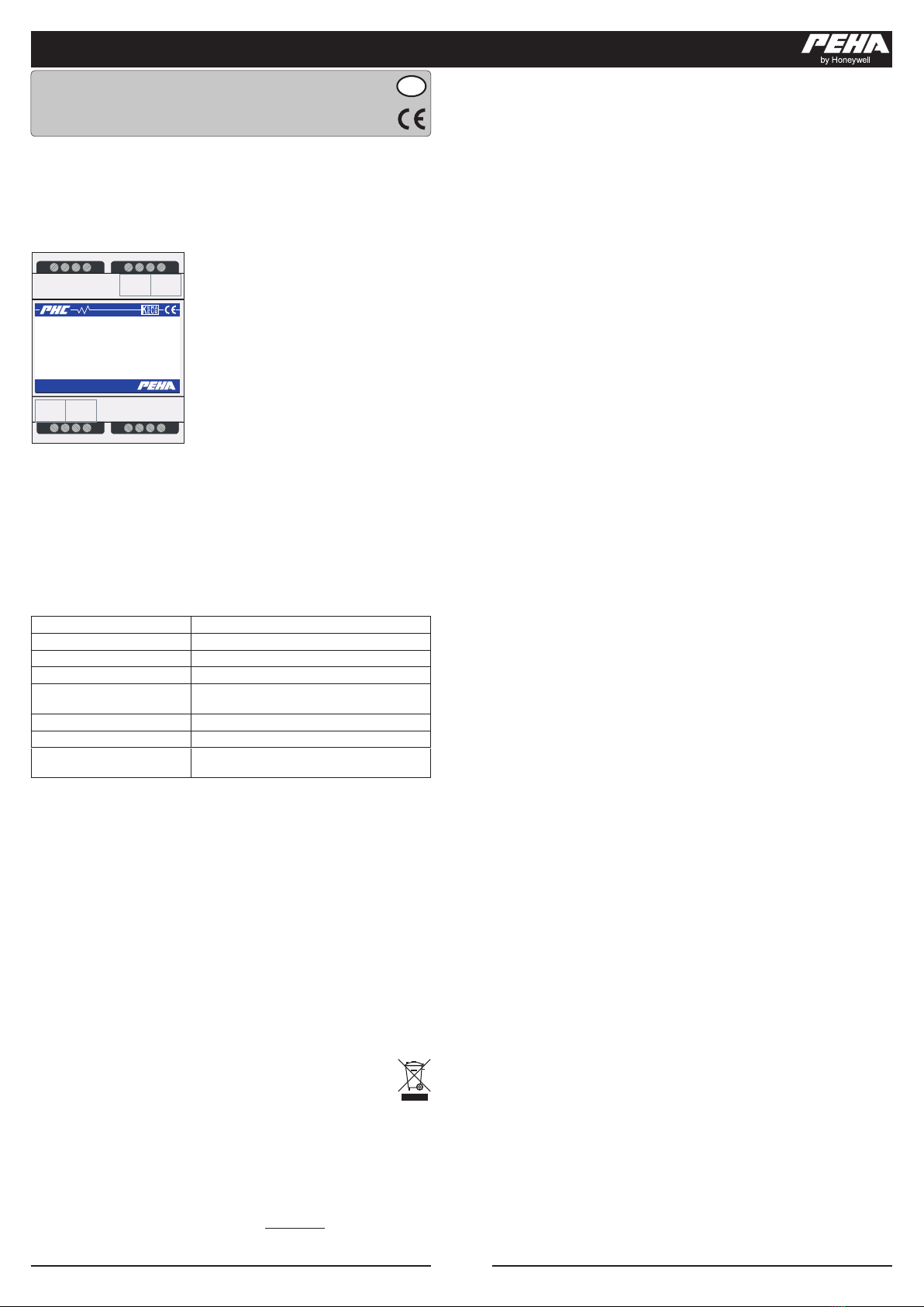
ANSCHLUSSBILD
Busverteilermodul
8 PHC Busanschlüsse
Art. Nr.: 940 BV
-B0V +A + 24 V-B0V +A + 2 4 V
-B0V +A + 24 V-B0V +A + 2 4 V
940 BV
8 PHC Bus Connections
PHC System
Das PHC-Modul ist für die Montage auf eine 35mm
Hutschiene nach EN50022 im Verteilungs-Ein/Auau-
gehäuse mit geschraubter Abdeckung konzipiert.
Die Geräte können direkt nebeneinander eingebaut
werden.
ANSCHLUSS DATENVERBINDUNG
Die Verbindung über die Schraubklemmen zu anderen PHC-Busverteilern, PHC UP-Modulen
oder PHC-Adapterkabeln wird üblicherweise über eine JY(ST)Y 2x2x0,8 mm Leitung
hergestellt. Beim Anschließen miels der eingebauten Schraubklemmen ist darauf zu
achten, dass die aufgedruckte Anschlussbelegung eingehalten wird. Vor dem Arbeiten an den
Busanschlüssen ist die Spannungsversorgung abzuschalten, um Kurzschlüsse zu vermeiden.
Die Ankopplung von PHC-Modulen an den PHC-Bus kann mit den PHC-Busleitungen über die
Modularsteckverbinder der PHC-Module und des PHC-Busverteilermoduls hergestellt werden.
Vor dem Trennen der PHC-Busleitung ist die Stromversorgung abzuschalten.
TECHNISCHE DATEN
Spannungsversorgung Wird nicht benögt
Eigenverbrauch Kein Eigenverbrauch
Umgebungstemperatur +10 bis + 50 °C
Lagertemperatur -20 bis + 60 °C
Anschlüsse PHC-Bus 4 x Schraubklemmen (0V, +A, -B, +24V)
4 x Modularbuchsen 6-polig
Schraubklemmen 2 x 1,5 mm² oder 1 x 2,5 mm²
Schutzart IP20
Abmessungen Breite = 72 mm (4TE)
Höhe = 55mm
GARANTIEBESTIMMUNGEN
Diese Bedienungsanleitung ist Bestandteil des Gerätes und der Garanebedingungen.
Sie ist dem Benutzer zu überreichen. Die technische Bauart der Geräte kann sich ohne
vorherige Ankündigung ändern. PEHA Produkte sind mit modernsten Technologien nach
geltenden naonalen und internaonalen Vorschrien hergestellt und qualitätsgeprü.
Sollte sich dennoch ein Mangel zeigen, übernimmt PEHA, unbeschadet der Ansprüche des
Endverbrauchers aus dem Kaufvertrag gegenüber seinem Händler, die Mängelbeseigung
wie folgt:
Im Falle eines berechgten und ordnungsgemäß geltend gemachten Anspruchs wird PEHA
nach eigener Wahl den Mangel des Gerätes beseigen oder ein mangelfreies Gerät liefern.
Weitergehende Ansprüche und Ersatz von Folgeschäden sind ausgeschlossen. Ein berechgter
Mangel liegt dann vor, wenn das Gerät bei Übergabe an den Endverbraucher durch einen
Konstrukons-, Fergungs- oder Materialfehler unbrauchbar oder in seiner Brauchbarkeit
erheblich beeinträchtigt ist. Die Gewährleistung entfällt bei natürlichem Verschleiß,
unsachgemäßer Verwendung, Falschanschluss, Eingri ins Gerät oder äußerer Einwirkung. Die
Anspruchsfrist beträgt 24 Monate ab Kauf des Gerätes durch den Endverbraucher bei einem
Händler und endet spätestens 36 Monate nach Herstellung des Gerätes. Für die Abwicklung
von Gewährleistungsansprüchen gilt Deutsches Recht.
ENTSORGUNG DES GERÄTES
Werfen Sie Altgeräte nicht in den Hausmüll! Zur Entsorgung des Gerätes sind die
Gesetze und Normen des Landes einzuhalten, in dem das Gerät betrieben wird!
Das Gerät enthält elektrische Bauteile, die als Elektronikschro entsorgt werden
müssen. Das Gehäuse besteht aus recycelbarem Kunststo.
KONTAKT
Telefon:............................ +49 (0)2351 185-0
Telefax: ............................ +49 (0)2351 27666
Internet: .......................... www.peha.de
DESCRIPTION
The PHC bus distributor module is used for PHC bus expansion. It is possible to connect several
PHC connecon cables or several installaon lines of the type JY(ST)Y 2x2x 0.8 mm. These bus
ports make it easier to, for instance, wire in other distributors and connect the PHC in-wall
modules.
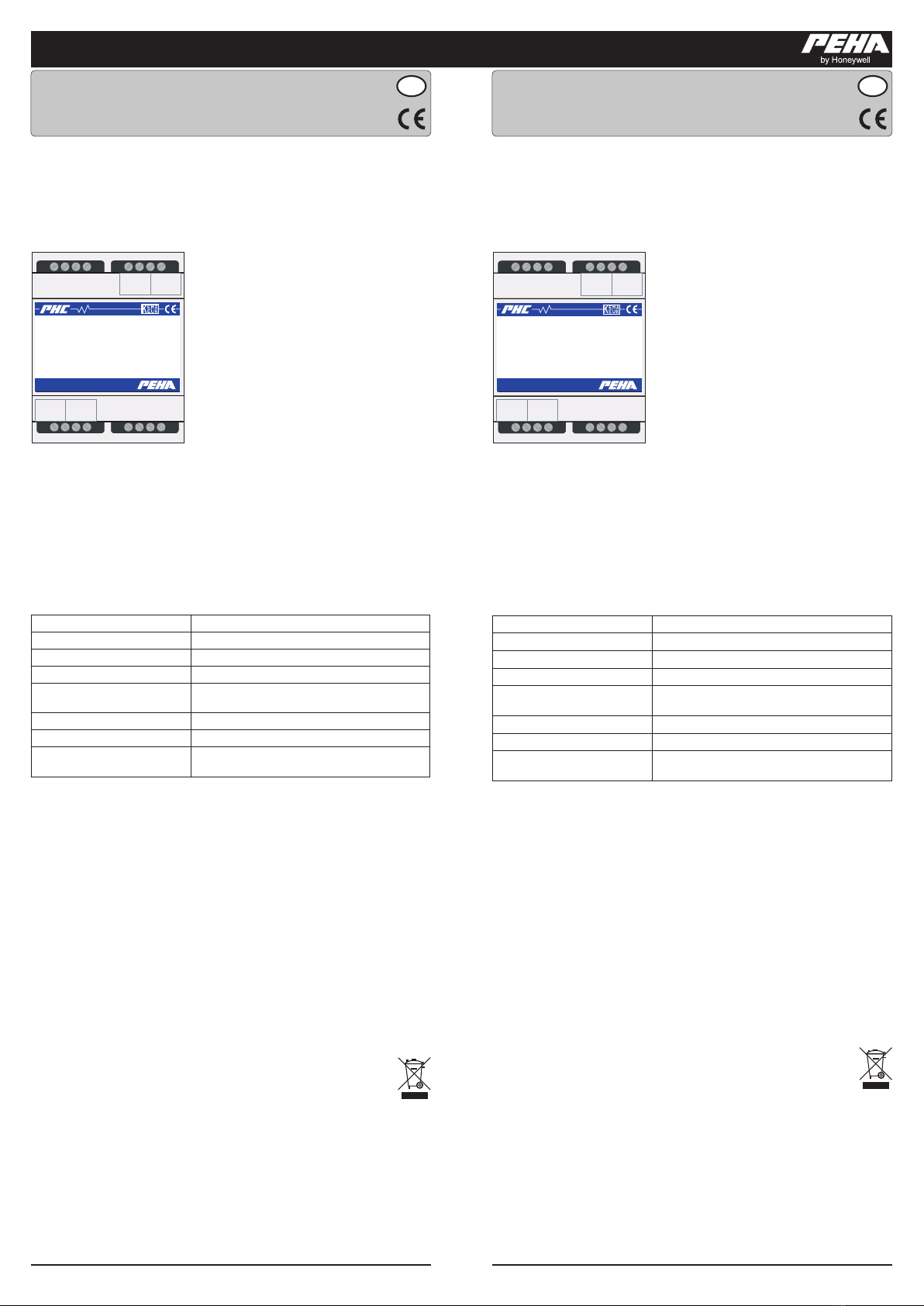
WIRING DIAGRAM
Busverteilermodul
8 PHC Busanschlüsse
Art. Nr.: 940 BV
-B0V +A + 24 V-B0V +A + 2 4 V
-B0V +A + 24 V-B0V +A + 2 4 V
940 BV
8 PHC Bus Connections
PHC System
The PHC module is designed for mounng on a 35
mm top hat rail according to EN 50022 in in-/on-wall
distribuon housing with screwed cover. The devices
can be mounted directly next to each other.
DATA CONNECTION
The connecon over the screw terminals to other PHC bus distributors, PHC in-wall modules
or PHC adapter cables is typically made with a JY(ST)Y 2x2x0.8 mm line.When connecng using
the built-in screw terminals, take care that the labelled connecon conguraon is observed.
Before working on the bus ports the power supply is to be switched o in order to avoid
short circuits. Connecon of PHC modules to the PHC bus can be made with the PHC bus
lines over the modular connectors of the PHC modules and the PHC bus distributor module.
Power needs to be switched o before disconnecng the PHC bus line.
TECHNICAL DATA
Power supply Not needed
Own consumpon No Own consumpon
Ambient temperature +10 to + 50 °C
Storage temperature -20 to + 60 °C
Connecons PHC-Bus 4 x screw terminals (0V, +A, -B, +24V)
4 x modular sockets 6-pin
Screw terminals 2 x 1,5 mm² or 1 x 2,5 mm²
Protecon level IP20
Dimensions Width = 72 mm (4TE)
Height = 55mm
WARRANTY CONDITIONS
These operang instrucons are an integral part of both the device and our terms of warranty.
They must be handed over to the user. The technical design of the appliance is subject to
change without prior nocaon. PEHA products are manufactured and quality-checked
with the latest technology according to applicable naonal and internaonal regulaons.
Nevertheless, if a product should exhibit a defect, PEHA warrants to make remedy as follows
(regardless of any claims against the dealer to which the end user may be entled as a result
of the sales transacon):
In the event of a jused and properly established claim, PEHA shall exercise its prerogave
to either repair or replace the defecve device. Further claims or liability for consequenal
damage are explicitly excluded. A jusable deciency is deemed to exist if the device exhibits
a structural, manufacturing, or material defect that makes it unusable or substanally impairs
its ulity at the me it is turned over to the end user. The warranty does not apply to natural
wear, improper usage, incorrect connecon, device tampering or the eects of external
inuences. The warranty period is 24 months from the date of purchase by the end user from
a dealer and ends not later than 36 months aer the device’s date of manufacture. German
law shall be applicable for the selement of warranty claims.
DISPOSAL OF THE DEVICE
Do not dispose of old devices in the household waste! The device must be disposed
of in compliance with the laws and standards of the country in which it is operated!
The device contains electrical components that must be disposed of as electronics
waste. The enclosure is made from recyclable plasc.
CONTACT
Telephone:......................+49 (0)2351 185-0
Fax: .................................+49 (0)2351 27666
Internet: .........................www.peha.de