pellenc FIXION 2 User manual

TYING MACHINE
FIXION 2
Operating instructions 29_133084-E
05/2020
ENG
Translation of the
original user guide
READ THE OPERATING INSTRUCTIONS
MANUAL CAREFULLY BEFORE USE
.


TYING MACHINE FIXION 2
29_133084-E
TABLE OF CONTENTS
1. INTRODUCTION ..................................................................................................................... 5
2. SAFETY ................................................................................................................................... 6
2.1. GENERAL POWER TOOL SAFETY WARNINGS .......................................................................... 6
2.1.1. WORK AREA SAFETY ...................................................................................................................... 6
2.1.2. ELECTRICAL SAFETY ....................................................................................................................... 6
2.1.3. PERSONAL SAFETY ......................................................................................................................... 6
2.1.4. POWER TOOL USE AND CARE ........................................................................................................ 7
2.1.5. BATTERY TOOL USE AND CARE ..................................................................................................... 7
2.1.6. SERVICE ........................................................................................................................................... 8
2.1.7. TOOL’S END-OF-LIFE MANAGEMENT .............................................................................................. 8
2.2. SAFETY WARNING THE TYING MACHINE ................................................................................... 8
2.3. SAFETY MEASURES ASSOCIATED WITH BATTERY USE ......................................................... 8
2.4. SAFETY MEASURES WHEN USING THE "PELLENC" CHARGER ............................................. 9
2.5. SAFETY SIGNAGE .......................................................................................................................... 9
2.6. PERSONAL PROTECTION EQUIPMENT ..................................................................................... 10
3. DESCRIPTION AND TECHNICAL CHARACTERISTICS .................................................... 11
3.1. DESCRIPTION ................................................................................................................................ 11
3.2. TECHNICAL FEATURES ............................................................................................................... 12
4. COMMISSIONING ................................................................................................................. 13
4.1. SETTING UP BELT AND HOLSTER ............................................................................................ 13
4.2. FITTING THE LATERAL REEL EQUIPPED WITH THE LARGE COIL ONTO THE BELT. .......... 13
4.3. PUTTING ADAPTABLE DISPENSER FITTED WITH THE SMALL COIL ONTO THE TYING
MACHINE. .............................................................................................................................................. 14
5. USE ....................................................................................................................................... 15
5.1. TYING MACHINE ON/OFF ............................................................................................................ 15
5.2. ADJUSTING THE TIGHTNESS OF THE TIE ................................................................................ 15
5.3. RELOAD THE LARGE COIL ......................................................................................................... 15
5.4. RELOAD THE SMALL COIL ......................................................................................................... 17
5.5. INSERT THE CORD INTO THE TYING MACHINE ...................................................................... 18
5.6. GRIP ............................................................................................................................................... 19
5.7. END OF COIL ................................................................................................................................ 21
5.8. CHARGING THE TOOL ................................................................................................................. 23
5.8.1. INSTRUCTIONS BEFORE CHARGING BUILT-IN BATTERY .............................................................. 23
5.8.2. THE DISPLAY SHOWING REMAINING BUILT-IN BATTERY CAPACITY ............................................ 23
5.8.3. CHARGING THE BUILT-IN BATTERY .............................................................................................. 24
6. MAINTENANCE .................................................................................................................... 27
6.1. INTERNAL CLEANING OF FIXION 2 ........................................................................................... 27
6.2. CHARGER ...................................................................................................................................... 29
3

TYING MACHINE FIXION 2
29_133084-E
6.3. MISC. MAINTENANCE .................................................................................................................. 29
6.4. BUILT-IN BATTERY REPLACEMENT .......................................................................................... 29
7. INCIDENTS AND TROUBLESHOOTING ............................................................................. 30
7.1. BUILT-IN BATTERY ....................................................................................................................... 30
7.2. CHARGER ...................................................................................................................................... 30
7.3. SUMMARY OF CHARGE INDICATOR AND BEEP MESSAGES ................................................ 30
8. STORAGE AND TRANSPORT ............................................................................................ 32
8.1. STORAGE ...................................................................................................................................... 32
9. ACCESSORIES AND CONSUMABLES .............................................................................. 32
10. WARRANTIES .................................................................................................................... 33
10.1. GENERAL WARRANTIES ........................................................................................................... 33
10.1.1. STATUTORY WARRANTY ............................................................................................................. 33
10.1.2. COMMERCIAL WARRANTYPELLENC ............................................................................................ 33
10.1.3. PAID AFTER-SALES SERVICE ...................................................................................................... 34
11. EC STATEMENT OF COMPLIANCE ................................................................................. 36
11.1. "EC" DECLARATION OF CONFORMITY: FIXION 2 ................................................................. 36
4

TYING MACHINE FIXION 2
29_133084-E
1. INTRODUCTION
Dear Customer,
Thank you for purchasing your Tying machine FIXION 2 . Correctly used and maintained, this tool will give a satis-
factory performance for many years.
Warning
Your device contains numerous recoverable or recyclable materials. Return it to your
dealer or, failing this, to an approved servicing centre to be treated.
Comply with the regulations in force in your country as concerns environmental protection associated with your
activity.
Warning
It is imperative that you read through the ENTIRE user’s manual before using or servicing the
tool. Always comply with the instructions and illustrations in the manual.
All through this user guide you will find advisory notes and information entitled: NOTE, IMPORTANT, ATTENTION
and WARNING.
The points marked “NOTE” indicate additional information.
The points marked “IMPORTANT” warn the user of a potential risk to the equipment.
The points marked “ATTENTION” warn the user of a potentially hazardous situation which if not avoided leads to
minor injuries.
The points marked “WARNING” warn the user of a potentially hazardous situation which if not avoided leads to
serious injury or death.
The warning indicates that damage resulting from failure to comply with the procedures and instructions is not
covered by the warranty and the owner will be liable for any repair costs.
Safety indications are also given on the tool; they remind you of the safety precautions to be taken. Identify and
read these indications before using the tool. Immediately replace any indications that may become partially illegible
or deteriorated.
Refer to Section 2.5, “Safety signage” for the location diagram of the safety stickers affixed to the tool.
No part of this manual may be reproduced without the written permission of the company PELLENC. The illustrations
given in this manual are for information purposes and are in no way contractual. The PELLENC company reserves
the right to make any modification or improvement to its products as deemed necessary without informing customers
already in possession of a similar model. This manual forms an integral part of the tool and must accompany the
tool if it changes hands.
5

TYING MACHINE FIXION 2
29_133084-E
2. SAFETY
2.1. GENERAL POWER TOOL SAFETY WARNINGS
Warning
Read all safety warnings, instructions, illustrations and specifications provided with this
power tool. Failure to follow all instructions listed below may result in electric shock, fire and/
or serious injury.
Note
Save all warnings and instructions for future reference.
The term "power tool" in the warnings refers to your mains-operated (corded) power tool or battery-operated (cord-
less) power tool.
2.1.1. WORK AREA SAFETY
1. Keep the work area clean and well lit. Cluttered or dark areas invite accidents.
2. Do not operate power tools in an explosive atmosphere, for example in the presence of flammable
liquids, gases or dust. Power tools create sparks, which can ignite dust or fumes.
3. Keep children and bystanders away while operating the power tool. Distractions can cause you to lose
control of the tool.
2.1.2. ELECTRICAL SAFETY
1. The power tool connector must be adapted to the socket. Never modify the connector in any way what-
soever. Do not use adapter plugs with earthed (grounded) power tools. Unmodified plugs and suitable
sockets reduce the risk of electric shock.
2. Avoid contact with earthed surfaces such as pipes, radiators, cookers, and refrigerators. There is an
increased risk of electric shock if your body is in direct contact with the ground.
3. Do not expose power tools to rain or damp conditions. The entry of water into a power tool increases the
risk of electric shock.
4. Do not mishandle the power cord. Never use the cord for carrying, pulling or unplugging the power
tool. Keep cord away from heat, oil, sharp edges and moving parts. Damaged or entangled cords increase
the risk of electric shock.
5. Use an extension cord suitable for outdoor use when operating power tools outdoors. Use a cord suitable
for outdoors to reduce the risk of electric shock.
6. Use a power supply protected by a residual current device (RCD) when the power tool is operated in a
damp location. Use of an RCD reduces the risk of electric shock.
Note
The term “Residual Current Device” (RCD) can be replaced by “Ground Fault Circuit Interrupter” (GFCI) or
“Earth Leakage Circuit Breaker” (ELCB).
2.1.3. PERSONAL SAFETY
1. Stay alert, watch what you are doing, and use common sense when operating the power tool. Do not
use a power tool while you are tired or under the influence of drugs, alcohol or medication. A moment
of inattention when using a power tool can result in serious personal injury.
6

TYING MACHINE FIXION 2
29_133084-E
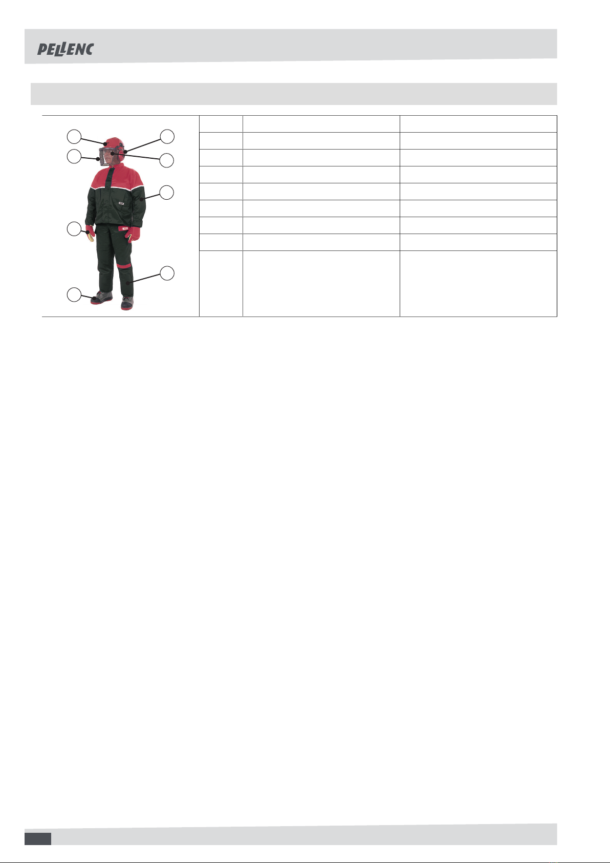
2. Use personal protective equipment. Always wear eye protection. Safety equipment such as dust masks,
non-slip safety shoes, helmets, or ear protection used at the appropriate times reduces injuries.
3. Avoid accidental starting of the tool. Make sure the switch is in the off position before you connect the
tool to the power source and/or battery pack, pick it up, or carry it. Carrying a power tool with your finger
on the switch or connecting a power tool with the switch in the ‘on’ position can cause accidents.
4. Remove any adjusting wrench before switching the electric tool on. A wrench left attached to a rotating
part can cause injury.
5. Do not rush. Keep proper footing and balance at all times. This provides better control of the power tool
in unexpected situations.
6. Dress appropriately. Do not wear loose clothing or jewellery. Keep hair and clothing away from moving
parts. Loose clothes, jewellery or long hair can get caught in moving parts.
7. If devices are provided for connecting dust extraction and collection equipment, ensure that these are
connected and properly used. Use of dust collection can reduce dust-related hazards.
8. Do not let familiarity gained from frequent use of tools allow you to become complacent and ignore tool
safety principles. A careless action can cause severe injury within a fraction of a second.
2.1.4. POWER TOOL USE AND CARE
1. Do not force the power tool. Use the power tool suited for the job. The adapted power tool does the work
better and more safely at the speed it was built to operate at.
2. Do not use the power tool if the switch does not allow it to be switched on and off. Power tools that
cannot be controlled by a switch are dangerous and must be repaired.
3. Unplug the tool from the socket or remove the battery (if possible) before any adjustment, change of
accessory or storage. These preventive safety measures reduce the risk of accidentally starting the power
tool.
4. When not in use, keep power tools out of the reach of children and do not allow persons unfamiliar
with the power tool or these instructions to operate it. Power tools are dangerous when operated by inex-
perienced users.
5. Maintenance of the power tool and its accessories is mandatory. Check that the moving parts are not
out of alignment or jammed, that there are no broken parts or that there is no other condition which
could affect the operation of the power tool. If damaged, repair the power tool before using it. Many
accidents are due to poorly maintained power tools.
6. Keep the cutting elements sharp and clean. Properly maintained cutting tools with sharp cutting elements
are less likely to jam and are easier to control.
7. Use the power tool, accessories, blades, etc. in accordance with these instructions, taking into account
the working conditions and the work to be done. Use of the power tool for operations different from those
intended could result in a hazardous situation.
8. Keep handles and grasping surfaces dry, clean and free from oil and grease. Slippery handles and grasp-
ing surfaces do not allow for safe handling and control of the tool in unexpected situations.
2.1.5. BATTERY TOOL USE AND CARE
1. Recharge only with the charger specified by the manufacturer. A charger that is suitable for one type of
battery pack may create a risk of fire when used with another battery pack.
2. Use power tools only with specifically designated battery packs. Use of any other battery packs may
create a risk of injury and fire.
3. When battery pack is not in use, keep it away from other metal objects, like paper clips, coins, keys,
nails, screws or other small metal objects, that can make a connection from one terminal to another.
Shorting the battery terminals together may cause burns or a fire.
4. Under abusive conditions, liquid may be ejected from the battery; avoid contact. If contact accidentally
occurs, wash away with water. If liquid contacts eyes, seek additional medical help. Liquid ejected from
the battery may cause irritation or burns.
5. Do not use a battery pack or tool that is damaged or modified. Damaged or modified batteries may exhibit
unpredictable behaviour resulting in fire, explosion or risk of injury.
6. Do not expose a battery pack or tool to fire or excessive temperature. Exposure to fire or temperature
above 130 °C may cause explosion.
7

TYING MACHINE FIXION 2
29_133084-E
Note
The temperature “130°C” can be replaced by the temperature “265°F”.
7. Follow all charging instructions and do not charge the battery pack or tool outside the temperature
range specified in the instructions. Charging improperly or at temperatures outside the specified range may
damage the battery and increase the risk of fire.
2.1.6. SERVICE
1. Have your power tool serviced by a qualified repair person using only identical replacement parts. This
will ensure that the safety of the power tool is maintained.
2. Never service damaged battery packs. Service of battery packs should only be performed by the manufac-
turer or authorized service providers.
2.1.7. TOOL’S END-OF-LIFE MANAGEMENT
1. When the tool reaches the end of its life, PELLENC keeps the end of life sheet of the equipment at
disposal. The end of life sheet provides instructions for safely removing components.
2.2. SAFETY WARNING THE TYING MACHINE
1. Never modify the connector in any way whatsoever.
2. Always switch off the battery when the machine is not in use (LED must be off).
3. Never use the tool if it is damaged, incorrectly set or incompletely assembled.
4. Never remove or disable a safety device. Have the safety device repaired if is faulty.
5. Do not disassemble the tying machine.
6. Please test the machine before use to check that it is working properly.
2.3. SAFETY MEASURES ASSOCIATED WITH BATTERY USE
1. If not using the battery unit, store it away from other metal objects such as paper clips, coins, keys, nails, screws
or other such small metal items that might form a connection between the two terminals. Creating a short-circuit
between the battery terminals can lead to burns or cause a fire.
2. Keep the battery out of the reach of children and place it on a non-combustible support.
3. Do not interfere with its cooling cycle.
4. Do not use or leave the battery near a heat source (> 60°C).
5. Do not leave the battery in direct, strong sunlight.
6. Do not expose the battery to microwaves or high pressure.
7. Do not immerse the battery in water.
8. The batteries must be charged in a dry, ventilated room at a temperature between 10°C and 25°C maximum,
away from any moisture.
9. If the battery is not used for 10 days, the battery will automatically discharge until it reaches its storage charge
rate, and then goes to sleep. It will heat up during this phase.
10. Over time, the capacity of your battery reduces. When it reaches half of its original battery-life operating time,
it should be replaced.
11. The battery may lose 1 to 4 % of its capacity when exposed to a temperature higher than or equal to 55 °C
for one week.
12. The charging location must be equipped with a class D fire extinguisher (for metal fires) in good working order.
13. The standards in effect must be complied with when either shipping a complete tool or a battery.
• A complete tool with a battery is a product that is classified as class 9, UN3481.
• Battery alone: product that is classified as class 9, UN3480.
14. Use of a battery other than that provided by Pellenc SA is dangerous (risk of serious injury). If a different battery
is used, Pellenc SA cannot be held responsible for any consequences.
8

TYING MACHINE FIXION 2
29_133084-E
15. The battery must be protected from any impact and must be positioned and secured appropriately during trans-
portation.
16. In the case of suspicious smoke, place the battery outside the charging area or transportation vehicle as far
away as possible from any inflammable material.
17. Never store a battery when its capacity is below 50 %. Recharge the battery before storage if the value is
below 50%.
18. In inappropriate conditions, a liquid can flow batteries; avoid contact with it. In the event of accidental contact,
rinse with water. In the event of contact with eyes, seek professional medical help. The liquid leaking from the
batteries can cause irritations or burns.
19. Pellenc power tools must only be used with the battery units designed for the purpose. Use of other battery
units can present a risk of injury and fire.
20. Only recharge using the charger indicated by the manufacturer. A charger adapted to one type of battery unit
may present a fire risk if used with a different battery unit.
21. Do not use the battery for any purpose other than that initially envisaged (exclusively for use with Pellenc tools).
22. At the end of its life, the battery must be returned to the authorized distributor from whom it was purchased to
be recycled in accordance with waste regulations.
23. Fragile case, contains an electronic board and lithium.
2.4. SAFETY MEASURES WHEN USING THE "PELLENC" CHARGER
1. When in operation, the charger’s temperature can reach 60°C. No flammable material must be within 1.5 metres
of the charger and battery.
2. Place the charger out of children’s reach and onto a non-combustible support.
3. Do not interfere with its cooling cycle.
4. The charger supplied with the battery is designed to recharge the battery. Do not charge non-rechargeable
batteries.
5. The charging location must be equipped with a class D fire extinguisher (for metal fires) in good working order.
6. If the output cord is cut or damaged, bring the entire charger back to the authorised distributor where the tool
was purchased.
7. Only recharge using the "PELLENC" charger indicated by the manufacturer. A charger adapted to one type of
battery unit may present a fire risk if used with a different battery unit.
8. This charger is designed to charge the batteries of Pellenc's lithium tools.
9. Do not use it for any other purposes.
10. Children must be supervised to ensure they do not play with the charger.
11. Verify that the cable cannot be folded and does not touch hot surfaces or sharp edges.
12. Ensure good ventilation during the charge.
13. Never cover the charger. This charger must not be used outdoors.
14. Make sure the power connector is not exposed to water.
15. Never charge a damaged battery.
16. The grid connection must comply with national electrical regulations.
17. Check the cable of the charger before using it. Never use the charger if the cable is damaged
18. When the battery is charging, place the charger on a non-flammable support, more than 1.5 m away from any
flammable object.
2.5. SAFETY SIGNAGE
Do not expose to rain.
9

TYING MACHINE FIXION 2
29_133084-E
2.6. PERSONAL PROTECTION EQUIPMENT
Equipment Wear
1 Safety helmet --
2 Protective visor --
3 Protective gloves Recommended
4 Safety footwear Recommended
5 Ear protection --
6 Protective goggles Recommended
7 Jacket or over-sleeves --
1
2
3
8
4
6
7
5
8 Work trousers --
10

TYING MACHINE FIXION 2
29_133084-E
3. DESCRIPTION AND TECHNICAL CHARACTERISTICS
3.1. DESCRIPTION
Complete carry-case
1. Holster
2. User guide and warranty card
3. Charger unit with adapters
4. Belt
5. Disgorging scissors
6. Small coil with reel adaptable for use with the tool
7. Large coil with lateral reel
8. Fixion 2 tying machine
Fixion 2 tying machine
9. Hanging hook
10. Lock button for detachable dispenser
11. Swivel spout
12. Attachment hook
13. Upper guide
14. Guard
15. Inlet for tying cord
16. Charging connector
17. Handle with built-in battery (lithium-ion battery)
18. Twister
19. Operating trigger
Fixion 2 display
20. Tool on/off button
21. Gauge display
22. Power on LED for tool.
23. “MODE” button (1 to 4 twist selector)
11

TYING MACHINE FIXION 2
29_133084-E
Fixion 2 charger
24. Connector adapters
25. Li-lon battery charger
26. Charger manual
3.2. TECHNICAL FEATURES
Max tying capacity 25 mm
Power supply voltage of tying machine 10.9 V
Charger supply voltage 12.6V DC 500mA output
Li-lon battery capacity 38 Wh 3.5 Ah
Charging time 8 hours
Tying machine operating capacity before recharging up to 15,000 ties
Large reel cord length (carried by user) about 200 m/coil
Corresponding no. of ties on large reel around 1500 ties
Small reel cord length (carried on tool) about 60 m/coil
Corresponding no. of ties on small reel Around 450 ties
Weight of tying machine alone 800 g
Weight of tying machine with adaptable dispenser and small reel 990 g
Weight of whole assembly worn on belt (lateral dispenser with large reel) 640 g
Total vibration values (triax vector sum) determined in accordance with the
EN 62841-1 standard (uncertainty of K=1.5 m/s²)
ah < 2.5 m/s²
Noise value measured according to Standard EN 62841-1
Acoustic power level measured (uncertainty of K=3 dB) LWA= 80 dB
Level of acoustic pressure measured at the work station (uncertainty of
K=3 dB)
LpA= 69 dB
12

TYING MACHINE FIXION 2
29_133084-E
4. COMMISSIONING
4.1. SETTING UP BELT AND HOLSTER
1. Remove the belt (4) from the carry-case.
2. Put the holster (1) in place on the belt (4), on the left or right side according to whether you are left or right-
handed.
3. Place the belt (4) at your back, around your waist.
4. Adjust the length of the belt (4) to fit you.
4.2. FITTING THE LATERAL REEL EQUIPPED WITH THE LARGE COIL ONTO THE BELT.
1. Clip the reel fitted with the large coil onto the belt.
Note
The reel cover is placed on the user’s right side by
default. This is so that the reel clips are on the right
of the belt, with the cord outlet towards the front.
2. The reel clips pivot horizontally and vertically as re-
quired.
3. To switch the cover over to the left-handed version:
Open the reel cover and unclip it.
13

TYING MACHINE FIXION 2
29_133084-E
4. Reverse the cover and clip it onto the reel.
5. Close the cover.
Note
In this configuration, the reel clips are on the left of
the belt, with the cord outlet towards the front.
4.3. PUTTING ADAPTABLE DISPENSER FITTED WITH THE SMALL COIL ONTO THE TYING
MACHINE.
1. Remove the guard (14) on the back of the tying ma-
chine.
2. Place the guard (14) into the slot reserved inside the
carrycase.
3. Put the small coil in place with the adaptable dis-
penser (6) instead of the guard (14).
14

TYING MACHINE FIXION 2
29_133084-E
5. USE
5.1. TYING MACHINE ON/OFF
The tying machine is started and stopped with the start/stop button (20).
5.2. ADJUSTING THE TIGHTNESS OF THE TIE
You can adjust the tightness of the tie to suit the type of wood you have to tie in place, by using the MODE button (23).
Table of equivalences
“MODE” button 1 2 3 4
Number of twists 3 5 7 8.5
5.3. RELOAD THE LARGE COIL
1. Block the rear flange and turn the front flange clock-
wise to unlock it.
2. Remove the front flange from the lateral dispenser
(7).
15

TYING MACHINE FIXION 2
29_133084-E
3. Put the tie reel in place: Match up the 4 straps with
the 4 flats on the hub of the lateral dispenser (7) and
make sure the end of the tie is coming out in the right
direction.
Note
The coil must unwind clockwise through the outlet
opening of the lateral dispenser (7) (right-handed
user). The coil must run counterclockwise through
the exit port of the lateral dispenser reel (7) (left-
handed user).
4. Replace the front flange on the hub of the lateral dis-
penser (7).
5. Block the rear flange and turn the front flange an-
ti-clockwise to lock it.
6. Open the cover of the reel and pass the cord through
the opening.
7. Cut and remove the 4 straps with the disgorging
scissors (5).
8. Close the cover and unwind the cord to the desired
length.
16

TYING MACHINE FIXION 2
29_133084-E
5.4. RELOAD THE SMALL COIL
1. Block the rear flange and turn the front flange clock-
wise to unlock it.
2. Remove the front flange from the adaptable dis-
penser (6).
3. Put the tie reel in place: Match up the 4 straps with
the 4 flats on the hub of the adaptable dispenser (6)
and make sure the end of the tie is coming out in the
right direction.
Note
The coil must unwind clockwise.
4. Replace the front flange on the hub of the adaptable
dispenser (6).
5. Block the rear flange and turn the front flange an-
ti-clockwise to lock it.
17

TYING MACHINE FIXION 2
29_133084-E
6. Cut and remove the 4 straps with the disgorging
scissors (5).
5.5. INSERT THE CORD INTO THE TYING MACHINE
Large coil:
1. Insert the tie, flat, into the opening (15) of the tying
machine until the tie cord reaches the end stop.
Note
The coil must unwind clockwise through the outlet
opening of the lateral dispenser (7).
Small coil:
1. Insert the tie, flat, into the opening (15) of the tying
machine until the tie cord reaches the end stop.
2. Make sure the tie is inserted from below and not from
above.
Note
The coil must unwind clockwise.
18

TYING MACHINE FIXION 2
29_133084-E
3. Start the tying machine (see Section 5.1, “Tying ma-
chine on/off”).
4. Press the trigger (19) (a single press) to push the tie
through to the hook (12).
5. Check that no scrap of cord remains trapped in the
twister (18), make one empty tie to test it, and re-
move this tie.
5.6. GRIP
It takes a few hours handling to become familiar with the tying machine. The tying process is not automatic. To
ensure your tool is working properly, and you are comfortable with it, always comply with the following conditions:
• When you use the large coil, keep the assemblies properly aligned: reel / cord / tying machine.
• When you use the small coil, check that the tie has been properly inserted into the intake opening of the tying
machine.
Important
The cord must not be held at the tying machine intake.
Warning
Avoid any malfunction by making sure the cord is not bent at the tying machine intake opening.
The tying machine must be used at a temperature of between -5° and +35°C.
19

TYING MACHINE FIXION 2
29_133084-E
Correct position of the cord when using the small coil.
Incorrect position of the cord when using the small coil.
Correct position of wood in the tying machine.
Note
The wood must be positioned against the swivel
dispenser (11) so the twister (18) can attach the tie
correctly on the metal wire.
20
Other manuals for FIXION 2
2
Table of contents
Other pellenc Power Tools manuals
Popular Power Tools manuals by other brands

Bosch
Bosch FNS138-23 Operating/safety instructions

Craftsman
Craftsman 152.229020 instruction manual

Kraissmann
Kraissmann 2001HLP3 user manual

Scheppach
Scheppach HP1100S Translation from the original instruction manual

Porter-Cable
Porter-Cable 6603 instruction manual

Makita
Makita DTW701ZJ instruction manual