Duomo BX116 User manual

Microprocessor control
Wall mounted
16 zone protection (across 2 zones)
4 - 20mA signal input
Measuring range 0 - 20% L.E.L. /
0 - 300ppm
IP55 protective rating
EN50194 for explosive gases
EN50291 for toxic gases
3 year guarantee
Application
Duomo is recognised within the gas industry for
providing a comprehensive range of low cost, high
reliability gas detection for many applications. We have
installed and commissioned natural gas and carbon
monoxide sensors in applications such as boiler rooms,
kitchens, car parks, aircraft hangers, factories and
shopping centres.The BX116 is the command centre for
the complete range of Duomo gas sensors. All Duomo
products are manufactured to meet relevant European
Normatives and proposals for explosive and toxic gases.
Features
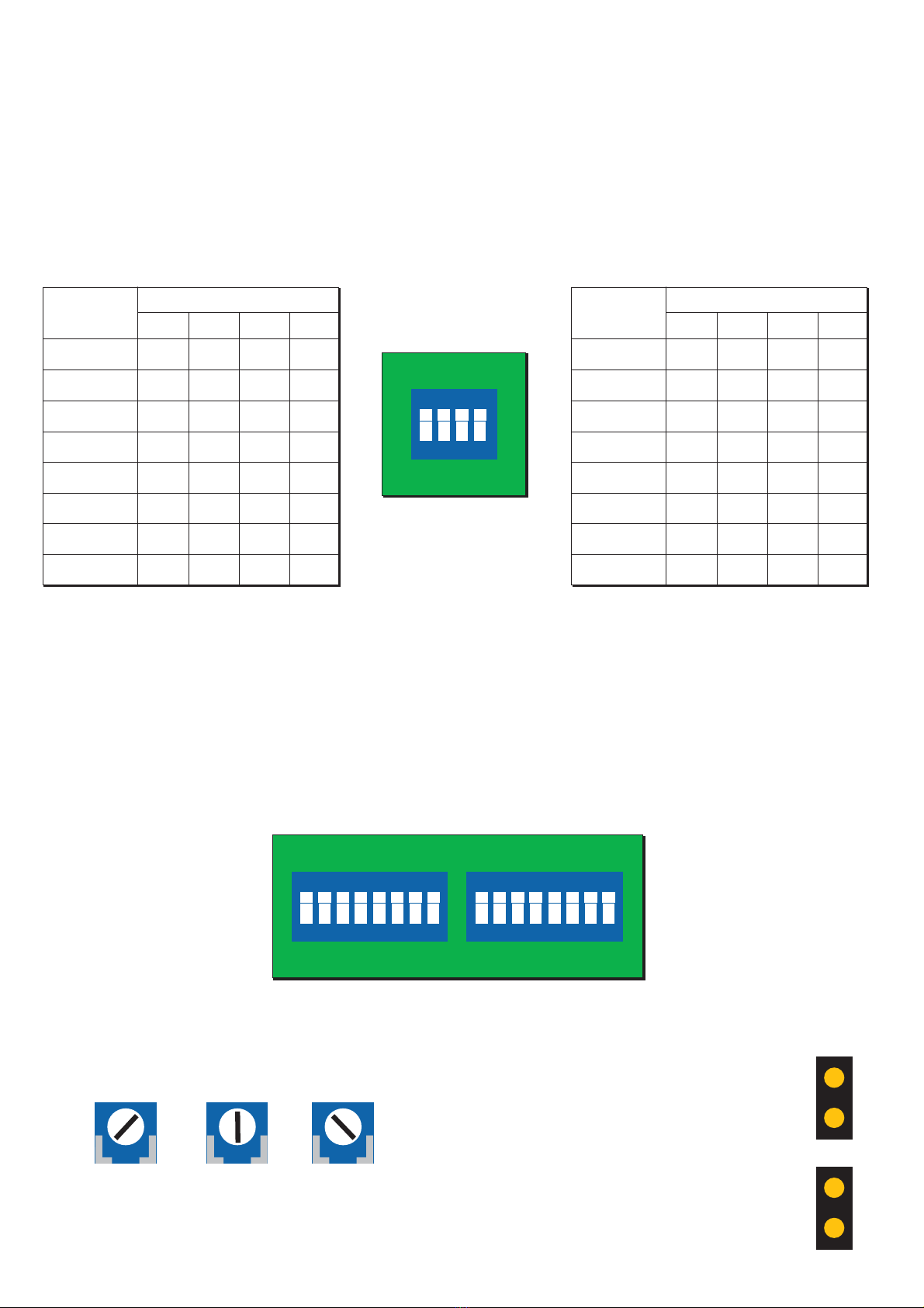
The BX116 is a wall mounted microprocessor based gas
detector control unit. It can be configured to meet
customer requirements. The following parameters can
be changed using on board DIP switches:
Number of sensors from 1 to 16
Type of gas to be sensed (explosive or toxic)
Main alarm delay period (3 or 20 seconds)
Main alarm relay action (latching or auto-reset)
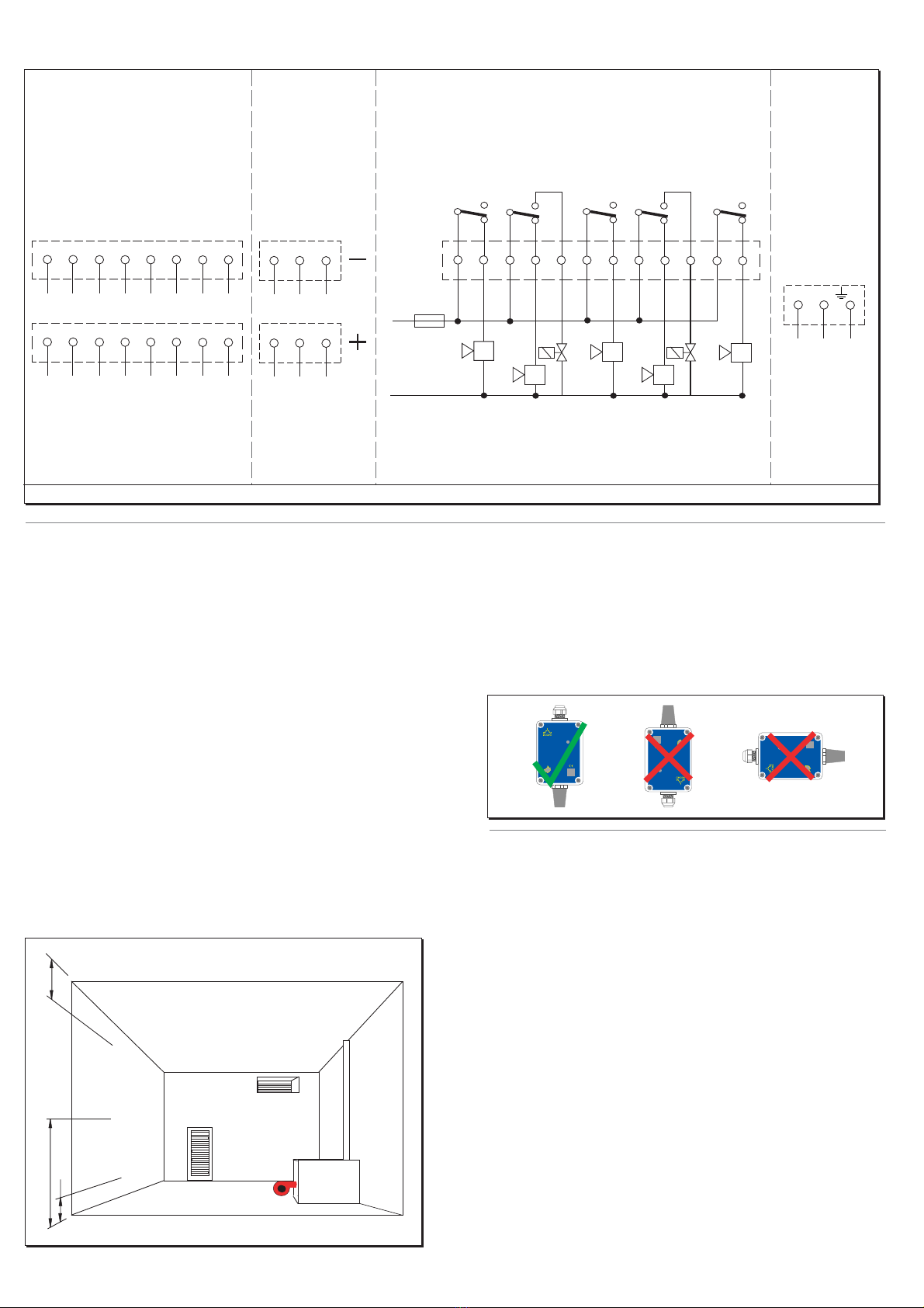
The BX116 has two plug in terminal blocks. One is for
the incoming mains supply and alarm circuit wiring and
the second is for connecting the sensor wiring. This
reduces the chance of incorrect site wiring. The front
panel has two banks of eight lights indicating, in
rotation, which probe is currently monitoring and a
bright display showing the LEL or PPM gas
concentration measured.
Operation
When the remote sensor detects the presence of the
targetgasa4-20mA signal is sent to the detector,
proportional to the level of gas. The BX116 then
operates a pre-alarm relay - used for remote sirens or
visual indicators. If the level of gas continues to rise then
the second pre-alarm is actuated. In the case of
explosive gases, when the level of gas reaches 20%
L.E.L., the main alarm relay is activated to break the
electrical supply to the gas safety shut-off valve (SSOV).
The BX116 also has a separate volt-free sensor fault relay
that actuates if the correct return signal is not sensed by
the detector. The BX116 can detect both explosive and
toxic gases.
CAUTION!
Carefully read the following instructions prior to
installation of this device. Always keep this pamphlet for
future reference.Ensure that the gas detection system is
wired correctly and is only used for the purpose for
which it is intended.
Duomo gas proving systems - Duomo gas detection - Duomo carbon dioxide sensors - Duomo ventilation interlocks - Are available direct or from all major stockists
BX116 Gas Detector
i

Key
Duomo gas proving systems - Duomo gas detection - Duomo carbon dioxide sensors - Duomo ventilation interlocks - Are available direct or from all major stockists
Overall Dimensions
GS300M Fascia & P.C.B. Layout
1. Power On - Lights when supply voltage is applied.This light flashes during self diagnostics start up.
2. Battery - Lights when the BX116 is powered by the standby battery.When flashing the standby battery has low charge.
3. Fault - Indicates a short circuit, sensor fault, loss of signal or incorrect connection of the sensor.
4. Test/Reset - When pressed checks the sequence and function of the BX116 / Press this to reset the detector after an
alarm or sensor fault condition
5. Zone 1 Indication - These L.E.D.'s represent the Zone 1 sensors and flash when a sensor is connected.
6. PPM L.E.D. - This lights when the jumper switch for display data is set to read in parts per million (PPM).
7. Display - Shows the current reading of gas concentration for the current sensor displayed.
8. Pre-Alarm (Zone 1) - 8% L.E.L. concentration of gas detected in Zone 1. Pre-alarm relay actuated.
9. Main Alarm (Zone 1) - 20% L.E.L. concentration of gas detected in Zone 1. Main alarm relay actuated.
10. Pre-Alarm (Zone 2) - 8% L.E.L. concentration of gas detected in Zone 2. Pre-alarm relay actuated.
11. Main Alarm (Zone 2) - 20% L.E.L. concentration of gas detected in Zone 2. Main alarm relay actuated.
12. % LEL L.E.D. - This lights when the jumper switch for display data is set to read in lower explosive limit (LEL).
13. Zone 2 Indication - These L.E.D.'s represent the Zone 2 sensors and flash when a sensor is connected.
14. No. of Sensors Switches - DIP switches allowing you to select how many sensors can be attached to the BX116.
15. Display Data Jumper - Allows you to select (via a jumper) whether the display reads in PPM or LEL.
16. Alarm Threshold Selector - Allows you to change the threshold at which the unit goes into alarm.
17. Sensor Selector Switches - Determines which sensors are currently working. MUST BE OFF TO ACTIVATE SENSOR.
18. Memory Switches - Determines whether or not the unit automatically resets after the gas concentration levels drop.
19. Sensor Connection Plug - Connection for the incoming return cable from the sensor.
20. Sensor Power Supply - Connections to power the sensors.
21. Relays - Connections for the relay outputs and fault relay.
22. Power Supply - Incoming power supply.
3
1
8
7
8
9
10
11
12
13
1
3
6
1
2
4
3
5
7
1
2
3
4
5
6
213 91011127684521376845213
213
76845213
Ph N
ON
21 43
ON
21 43 65 87
ON
21 43 65 87
BX116
Multi-channel Gas Detection System
POWER PRE ALARM
ZONE 1
ZONE 2
MAIN ALARM
123
PPM %LEL
456
PRE ALARM
MAIN ALARM
BATTERY
16
15
18
FAULT
TEST-RESET
78
12345678
19 20 2221
14
17

Duomo gas proving systems - Duomo gas detection - Duomo carbon dioxide sensors - Duomo ventilation interlocks - Are available direct or from all major stockists
Typical Wiring Schematic for BX116
Electrical Installation Installing A Sensor
The BX116 is a safety device designed to give audible
alarms and automatically provide latched electrical
isolation of associated gas safety shut off valves in the
event of a gas leak or build up of toxic gases. The sensor
can be located up to 100m from the gas detector. Cable
size should be 1mm2 CSA. If the sensor cables are run
seperately in specific conduit it is not essential to use
screened cable but if the cables are routed through
conduit or trunking containing other wiring the use of
screened cable is advisable. The wiring should be
performed by a qualified person in accordance with
current regulations. The plug-in terminal rail makes
installation easy and quick. Do not mount close to any
heat source or in an area where moisture is likely to effect
operation.The IP rating of this unit is IP44. Sensors should
be positioned as shown below. If you require any
guidance on this please call our technical help on 01905
797989.
The sensors must be mounted as shown below with the
sintered head pointing vertically down. When replacing
sensors never seperate a sensing head from its PCB. The
sensor will have been calibrated using this particular
board and therefore will not function correctly with any
other.
Important Notes
Always check the wiring before powering up the
system.
Do not test this sensor with anything other than
Duomo test gas (see 'BX116 Operation' section for
further information). Concentrations above this will
damage the sensor and shorten sensor life. The
installation of this gas detector does not release the
user from observing all the regulations concerning the
characteristics, installation and and the use of gas
appliances; the ventilation of the environment and the
elimination of combustion products in accordance with
the local recommendations, regulations and bylaws. For
any damage caused to people, property or animals
resulting from incorrect connection, installation or
application of this gas detector Duomo will not be held
responsible or liable. To ensure correct function after
installation Duomo provide a commissioning service
using calibrated test gases. For this service call 01905
797989.
SGM595
autosetting
ON
SGM595
autosetting
ON
SGM595
autosetting
ON
300
1600
300
Natural Gas
Carbon
Monoxide
L.P.G.
Note: Connections for other detectors may differ. Check detector datasheet wiring schematic. 1mm2CSA cable only
Mains power
supply
Relay outputs
21 321 3
8
7
6
5
4
21 38
7
6
5
4
Return cables from sensors
ZONE 2
ZONE 1
ZONE 2
ZONE 1
Power supply
to sensors
21 3
21 312
111098
7
6
5
4
FAULT
RELAY
PRE-
ALARM
ZONE 1
MAIN
ALARM
ZONE 1
MAIN
ALARM
ZONE 2
PRE-
ALARM
ZONE 2
NCNC NC
NONO NO
C
NC
NO
CC
NC
NO
CC
3/5A
Power
Supply 230V
AC
NPh

Duomo gas proving systems - Duomo gas detection - Duomo carbon dioxide sensors - Duomo ventilation interlocks - Are available direct or from all major stockists
Configuring The BX116
The BX116 has three banks of DIP switches on the PCB. The set of switches on the rear of the front of the unit is used to
control the LED's that represent the number of sensors connected to the system. The remaining switches are used to
activate/deactivate the sensors themselves.
Controlling the LED's that represent connected sensors
The front of the BX116 has two banks of eight LED's that represent each connected sensor. The LED's cycle through each
connected sensor and the associated gas concentration is displayed above. The table below shows what combination the
DIP switches must be in to display and cycle through the correct number of LED's.
Pre alarm threshold
The pre alarm on the BX116 can be altered to one of three
thresholds;
13% LEL 15% LEL 18% LEL
Turn the potentiometer all the way to the right for 18%, to
the middle for 13% and all the way to the left for 8%
Changing display units
The BX116 can display the current gas
concentration detected in either LEL or
ppm.
This is done by closing one of two jumpers
on the PCB on the rear of the door of the
unit. Closing the upper jumper sets the unit
to LEL. Closing the lower jumper sets the
unit to ppm.
Disabling or uninstalling sensors
The BX116 can accept up to 16 sensors, divided into two zones.You should deselect the DIP switch for any sensors that are
not connected. Not doing so could cause the unit to go into fault. If you experience a faulty sensor, disabling it via its
corresponding switch will return the BX116 to normal operation, allowing you to fix the sensor with uninterrupted
coverage. PLEASE NOTE: In order to turn the sensor ON, the switch must be in the DOWN position.
For example if you have 11 sensors connected, the DIP switches would need to be set to the following;
ON-OFF-ON-OFF
Y
43
ON
21
Y
ON
12345678
Y
ON
12345678
Sensor
Zone 1
Micro Switch
1
1
OFF
OFF
OFF
OFF
OFF
OFF
OFF
OFF
234
2
3
4
5
6
7
8
OFF
OFF
OFF
OFF
ON
ON
ON
ONON
ON
ON
ON
ON
ON
ON
ON
OFF
OFF
OFF
OFF
OFF
OFF
OFF
OFF
Sensor
Zone 2
Micro Switch
9
12 34
10
11
12
13
14
15
16
OFF
OFF
OFF
OFF
ON
ON
ON
ONON
ON
ON
ON
ON
ON
ON
ON
ON
ON
ON
ON
ON
ON
ON
ON
OFF
OFF
OFF
OFF
OFF
OFF
OFF
OFF

Duomo gas proving systems - Duomo gas detection - Duomo carbon dioxide sensors - Duomo ventilation interlocks - Are available direct or from all major stockists
BX116 operation
Maintenance procedure
This detector must be function checked as described above using calibrated test gas every 6 months. To arrange for a
Duomo engineer to conduct this work or to arrange a service contract please call 01905 797989.
Before powering up the BX116 once again check that all electrical connections are correct.
1. Apply 230V supply to the Ph and N terminals. Ensure that the correct fuse is used in the supply. (3 or 5A max.)
2. All of the lights on the fascia will light up in turn.This will take approximately 20 seconds.This checks the function of
all the L.E.D.'s.
3. The ON L.E.D. will remain flashing for about 90 seconds.This is the sensor warm-up period.The gas detector will not
provide gas detection during this period.When the ON light becomes constant the detector is in operation.
4. By pushing and maintaining pressure on the manual TEST button a function test can be performed for all pre-alarm
relays and main alarm relay, together with L.E.D.'s and audible alarm.
The sequence will be:
a) The 8% L.E.L. / 120ppm and Pre-Alarm 1 L.E.D. will be actuated.The Pre-Alarm 1 relay will be changed over.
b) The 20% L.E.L. / 300ppm and Main Alarm L.E.D. will be actuated.The Main Alarm relay will be changed over.The
relevant Alarm L.E.D.'s will light to show which zones are in alarm.
By releasing the the manual TEST button the lights will go out and the audible alarm will cease. If a latched alarm
function on the main relay is configured this will remain on until the RESET button is pressed.
5. In order to conduct a full function test it is essential to use Duomo or equivalent calibrated test gas.The maximum
concentrations are;
- 40% L.E.L. for methane in air
- 350ppm for carbon monoxide
- 0.85% (MOL) for propane
Any higher than this can reduce sensor life. NOTE: NEVER TEST USING NEAT GAS.THIS WILL POISON THE SENSOR.
6. To simulate a sensor fault situation disconnect the sensor plug.The detector will go into a FAULT alarm and the sensor
fault relay will be actuated.This will close the contacts between terminals 4 and 5 and open the contacts between
terminals 10 and 12 (Main Alarm relay).When the plug is reconnected the detector can be reset.

Duomo gas proving systems - Duomo gas detection - Duomo carbon dioxide sensors - Duomo ventilation interlocks - Are available direct or from all major stockists
Troubleshooting
In case of alarm
Extinguish any naked flames.
Do not switch lights or electrical devices on or off.
Open all windows and doors to increase ventilation.
If the 'ALARM' L.E.D. is off the levels of gas have dropped. A responsible, qualified person is now safe to find the cause
of the alarm.
If the alarm sound remains constant, and the cause is not evident or possible to eliminate turn off the emergency
isolation valves to the area and contact your gas provider emergency line.They will advice accordingly.
If you are experiencing difficulties, having made the checks listed above call Duomo on 01905 797989 for
technical assistance.
The Problem The Solution
No lights are illuminated on the fascia of the detector Check that the electrical supply is reaching the
device and that the plug in terminal rail is pushed
into place.
One or all of the sensor fault lights are illuminated
Sensor fault continues to alarm
The detector is subject to repeated alarms
The detector is in a main alarm condition and the
main gas valve is not closing
There is no supply to the solenoid valve
Check that the plug is inserted correctlty.
Check that the sensor wiring is correctly terminated
at both the sensor and detector. Check that 12V DC
is present at the sensor. The green light on the sensor
should be illuminated. Pressing the TEST button it is
possible to check the efficiency of the device and if
the sensors have been connected correctly.
Check that the connections are correct and that
power is supplied to the valve i.e. the valve is not
stuck in the open position. The function of the alarm
relays both Pre-Alarm and Main Alarm can be
checked by pressing the TEST button on the detector
fascia. Check that the main alarm action is configured
for a latching alarm (Switch 2 on 4th DIP switch).
Check the sensor wiring. If the red Overload LED is lit
a short circuit or overload has occurred on the sensor
or the connecting cable.
Ensure that there is not an occassional gas leak. This
may be due to a valve or joint which leaks under
pressure.
The Main Alarm relay is a volt-free contact, therefore
you must connect the live supply to the common of
the main alarm relay contacts terminal 10. A supply
wil then come from terminal 12 to the solenoid valve.
Sensor is connected, but no L.E.D. is lit on the front
fascia
Check that the DIP switch is set to the ON position

Commissioning
It is strongly recommended that this detector should be commissioned by Duomo Commissioning Engineers or
engineers approved by Duomo to carry out this work. A quotation for commissioning or service will be provided upon
request. Fax site details and preferred date for commissioning to 01905 774296 and the Duomo Service Department will
fax back confirmation.
The benefits of this equipment being commissioned by Duomo are:
On board spares. If for whatever reason this equipment doesn't function correctly Duomo engineers will have spares on
board to ensure that the commissioning is successful.
A Duomo Commissioning Certificate is provided.
It is prudent to make electrical connection to the detector terminal plus when withdrawn and leave the plug off the
detector so that the Duomo Engineer is the first to power up the unit on site. This allows wiring to be checked prior to
commissioning and avoids damage due to incorrect connection. Guarantees for this product will become void if damage
is caused by the installer.
Technical specification
Power Supply 230V AC 50Hz +/- 10%
Secondary Battery 12V DC +/- 10%
Power Consumption 30W maximum @ 230V
Power Consumption 25W maximum @ 12V
Relay contact range 10A 230V resistive - 5A 30V DC resistive
1st pre-alarm Can be set from 8% L.E.L. (120ppm) to 13% (250ppm)ofLEL
Main alarm Fixed at 20% L.E.L. / 300ppm
Sensor fault Short circuit, interruption, sensor deterioration
No. of remote sensors 16
MIcro switches to include/exclude sensors 1 per sensor
Monitored gas indication Through illuminated display
Input signal 4 - 20mA
Device precision 1% FS
Reaction time <10 seconds
Microprocessor 8 bytes
Working temperature -10 °C to 45 °C
Start-up self diagnostic delay 90 seconds
Suitable for use with sensor type SG500, SG590, SGM595, CO100A, CO200A, SG810
Maximum distance for sensor connection 100m
Cable diameter for sensors 1mm2 CSA
Dimemsions 360mm x 320mm x 135mm
Protective rating IP55
Guarantee 3 years from date of manufacture
Duomo gas proving systems - Duomo gas detection - Duomo carbon dioxide sensors - Duomo ventilation interlocks - Are available direct or from all major stockists - www.duomo.co.uk
Table of contents
Other Duomo Gas Detector manuals