Pentair Pool Products Pool and Spa IntelliComm User manual

IntelliComm™
Communication Center
(For use with the IntelliFlo®pump)
Installation and
User’s Guide
IMPORTANT SAFETY INSTRUCTIONS
READ AND FOLLOW ALL INSTRUCTIONS
SAVE THESE INSTRUCTIONS
P-INSB-ICOMM (08/’08)
Pentair Water Belgium bvba
Industriepark Wolfstee
Toekomstlaan 30
B-2200 Herentals - Belgium
+32 (0) 14.25.99.11
www.pentairpooleurope.com
English Deutsch Nederlands Français Español Italiano
9
16
23
30
37

© 2008 Pentair Water Pool and Spa, Inc. All rights reserved
This document is subject to change without notice
Trademarks and disclaimers: IntelliComm, IntelliFlo, and the Pentair Water Pool and Spa log are trademarks of
Pentair Water Pool and Spa, Inc. Other trademarks and trade names may be used in this document to refer to either
the entities claiming the marks and names or their products. Pentair Water Pool and Spa, Inc. disclaims proprietary
interest in marks and names of others.
Customer Support
HERENTALS, BELGIUM (8:30 A.M. to 4:30 P.M.) CET
Phone: + 32 (0) 14 25 99 11
Website: www.pentairpooleurope.com
Declaration of Conformity
We declare, under our sole responsibility, that the product identied in this declaration, and to which
this declaration relates, are in conformity with the protection requirements of Council Directive 98/
37/EEG
US Patents Pending
Manufacturer: Pentair Water Pool and Spa, Inc.
Important Safety Precautions 3
Section 1: Installation Steps Summary 3
Section 2: Kit Contents 3
Section 3: IntelliComm Communication Center 4
Section 4: Installing the IntelliComm enclosure 5
Section 5: Mounting the IntelliComm enclosure 5
Section 6: Connecting AC power wires to IntelliComm 6
Section 7: IntelliComm system wiring 7
Section 8: IntelliComm electrical specications 7
Section 9: Connecting the IntelliFlo communication cable 8
Contents
English
2

WARNING Read and follow all safety warning notices and instructions in this manual
before installing this product. Failure to follow safety warnings and instructions can result in
severe injury, death, or property damage.
CAUTION When using the IntelliComm communication center with the IntelliFlo pump,
it is recommended to wire the IntelliComm power center to a ground fault circuit-interrupter
(GFCI) to protect the circuit. A green colored terminal (or a wire connector marked “G”, “GR”,
“Ground” or “Grounding”) is provided within the terminal compartment in the Power Center
transformer enclosure. To reduce risk of electric shock, connect this terminal or connector to
the grounding terminal of your electric service or supply panel with a conductor equivalent in
size to the circuit conductors supplying this equipment.
WARNING To reduce the risk of injury, installation or service should only be attempted by
a qualied Pool Service Professional.
WARNING To reduce the risk of injury, do not permit children to use this product unless
they are closely supervised at all times.
CAUTION The IntelliFlo pump is for use with permanently installed pools and may also
be used with hot tubs and spas if so marked. Do not use with storable pools. A permanently
installed pool is constructed in or on the ground or in a building such that it cannot be
readily disassembled for storage. A storable pool is constructed so that it may be readily
disassembled for storage and reassembled to its original integrity.
IMPORTANT SAFETY PRECAUTIONS
Section 1
Installation Steps Summary
The recommended IntelliComm Communication Center installation steps are:
1. Review Important Safety Precautions: Review this important
information.
2. Review IntelliComm Overview: Review the product overview.
3. Installing IntelliComm: Installing the IntelliComm enclosure.
4. Connecting the AC wires to IntelliComm: Connecting AC wires to
terminal 1 and 2.
5. Connecting control input wires to IntelliComm: Connecting control input
wires to terminals 3 to 10 from source devices such as automation controllers or
heaters.
Section 2
Kit Contents
• IntelliComm Communication Center
• IntelliComm Installation Guide (this manual)
• Two wire RS-485 communication cable. Used to communicate to the IntelliFlo
pump from IntelliComm.
English
3

Attach IntelliFlo communication cable
wires to terminals 11 and 12
Attach incoming IntelliComm AC
power wires to AC terminals
1 and 2
Ground terminal Ground terminal
Attach control input wires to
terminals 3 through 10
IntelliComm Communication Center
Section 3
IntelliComm Communication Center
The Pentair IntelliComm communication center provides automatic control of the IntelliFlo
pump. The IntelliComm provides four pairs of input terminal connections. These inputs
connectors are actuated by either 15 VAC to 240 VAC or 15 VDC to 100 VDC from the source
device such as an automation controller, heater, or heat pump. Using the device’s inputs, the
four IntelliFlo external control programs can be enabled. If more than one input is active, the
highest program number will be communicated to the IntelliFlo pump.
The IntelliFlo pump is programmed to run at a specic speed for each input.
English
4

Section 4
Installing the IntelliComm enclosure
Install the IntelliComm enclosure at the equipment pad at a maximum of 15.24 m (50ft.) from
the IntelliFlo pump. Leave sufcient clearance on all sides of the enclosure. Be sure that the
communication cable from the IntelliFlo pump can reach the IntelliComm enclosure location.
The IntelliComm enclosure can be mounted on a wall or vertical at surface up to 15.24 m
(50ft.) away from the cell controller.
CAUTION: The IntelliComm communication center must be installed more than 2.44 m (8 ft.)
from the pool edges.
Note: For IntelliFlo 4 pump operating instructions, see the IntelliFlo 4 User’s Guide.
Section 5
Mounting the IntelliComm enclosure
1. Using a medium at blade screwdriver, loosen the two plastic screws on the front
cover and open the front cover.
2. Mount the enclosure on a at surface such as a wall or post. Mark each mounting
screw hole location.
3. Drill four 6 mm (1/4 inch) holes. Install anchors if necessary and one screw for each
enclosure hole.
4. Position the enclosure in place over the holes and install the four mounting screws
into the enclosure screw holes. Tighten the four screws to secure the enclosure.
Mounting screw access hole
Enclosure retaining screw
Mounting screw access hole
English
5

Section 6
Conecting AC power wires to IntelliComm
WARNING! IMPORTANT SAFETY PRECAUTIONS. BEFORE STARTING
READ THE FOLLOWING: Read all the safety precautions in this manual
before attempting any electrical wiring. Be sure to read and follow all safety
Instructions on page ii. Wiring should only be performed by a qualied
professional. When using electrical products, basic precautions should
always be followed, including the following:
• Grounding is required. The unit should be installed by a qualied service person
and grounded.
To connect the AC power wires to IntelliComm:
1. Connect the main AC power wires to the IntelliComm AC terminals number 1 and 2
as shown below.
2. Grounding: Attach incoming GROUND wire to the ground terminal as shown below.
Earth grounding is necessary to ensure personal safety and safety of equipment.
3. Close the front cover and tighten the two cover screws.
Attach incoming AC (100 VAC to 240 VAC 50/60 Hz)
wires to AC terminals 1and 2
Ground terminal
English
6

Section 7
IntelliComm system wiring
The IntelliComm provides four pairs of input terminals which can be actuated by either 15 to
240 VAC or 15 to 100 VDC from the source device, (automation controller, heater, heat pump
etc.). There are four IntelliFlo external control programs that can be enabled.
Note: The IntelliComm will always be congured to communicate to pump address 1.
IntelliComm system wiring table
Section 8
IntelliComm electrical specications
Power Requirements: The IntelliComm draws less than 1 amp. Over current protection of
the wires connecting the source device, (automation controller, heater, heat pump etc.) to the
IntelliComm must be provided at the source.
Inputs from remote device: The IntelliComm has four current sensing inputs that are
activated by either
15 VAC to 240 VAC or 15 VDC to 100 VDC.
Output to IntelliFlo pumps: The IntelliComm communicates with IntelliFlo pumps via a two
wire RS-485 Serial link.
Note: (*) indicates current controlled input, voltage independent.
Terminal number Terminal name Voltage Maximum current Phase type Frequency
1-2 Power supply 100 - 240 VAC 100 mA 1 Input 50/60 Hz
3-4 Program 1
15 -240 VAC
or
15 - 100 VDC
1 mA* 1 Input 50/60 Hz
5-6 Program 2
15 -240 VAC
or
15 - 100 VDC
1 mA* 1 Input 50/60 Hz
7-8 Program 3
15 -240 VAC
or
15 - 100 VDC
1 mA* 1 Input 50/60 Hz
9-10 Program 4
15 -240 VAC
or
15 - 100 VDC
1 mA* 1 Input 50/60 Hz
11
12
RS-485
+ Data: Yellow
- Data: Green
-5 to +5 VDC 5 mA 1 Output N/A
Ground
English
7

Section 9
Connecting the IntelliFlo communication cable
A two-wire communication cable is required to connect either the IntelliFlo pump to IntelliComm.
This allows the IntelliFlo pump to be controlled by IntelliComm. The cable pinout is shown
below.
IntelliFlo communication cable pinout
Note: Pins 1 - 5 are not used.
Pin 6 (Green) RS-485 (N) Pin 7 (Yellow) RS-485 (P)
English
8

© 2008 Pentair Water Pool and Spa, Inc. Alle Rechte vorbehalten.
Änderungen der Anleitung vorbehalten.
Marken und Haftungsausschluss: IntelliComm, IntelliFlo und das Logo von Pentair Water Pool and Spa sind
Marken der Pentair Water Pool and Spa, Inc. Andere in dieser Anleitung verwendete Marken und Handelsnamen
beziehen sich auf den jeweiligen Eigentümer der Marke oder des Namens bzw. auf dessen Produkte. Pentair Water
Pool and Spa, Inc. erklärt hiermit, keine Eigentumsansprüche auf Marken und Namen von anderen zu erheben.
Kundendienst
HERENTALS, BELGIEN (8:30 Uhr bis 16:30 Uhr) MEZ
Telefon: + 32 (0) 14 25 99 11
Internet: www.pentairpooleurope.com
Konformitätserklärung
Wir erklären unter unserer alleinigen Verantwortung, dass das in dieser Erklärung genannte Pro-
dukt, auf das sich diese Erklärung bezieht, den Schutzanforderungen der Richtlinie 98/
37/EWG entspricht.
In den USA zum Patent angemeldet
Hersteller: Pentair Water Pool and Spa, Inc.
Wichtige Sicherheitshinweise 10
Abschnitt 1: Reihenfolge der Installationsschritte 10
Abschnitt 2: Inhalt des Sets 11
Abschnitt 3: Der IntelliComm-Steuerkasten 11
Abschnitt 4: Einbauen des IntelliComm-Kastens 12
Abschnitt 5: Montieren des IntelliComm-Kastens 12
Abschnitt 6: Anschließen der AC-Stromkabel 13
Abschnitt 7: Anschließen der Steuerkabel 14
Abschnitt 8: Elektrische Daten 14
Abschnitt 9: Anschließen des IntelliFlo-Verbindungskabels 15
Inhaltsverzeichnis
Deutsch
9

WARNUNG Lesen Sie vor dem Installieren des Geräts alle Warnhinweise und
Anweisungen durch und befolgen Sie diese. Die Missachtung von Warnhinweisen und
Anweisungen kann zu Sachschäden sowie schweren Verletzungen, u. U. mit Todesfolge,
führen.
ACHTUNG Bei Verwendung des IntelliComm-Steuerkastens in Verbindung mit einer
IntelliFlo-Pumpe empfehlen wir, den IntelliComm-Schaltkasten zum Schutz des Stromkreises
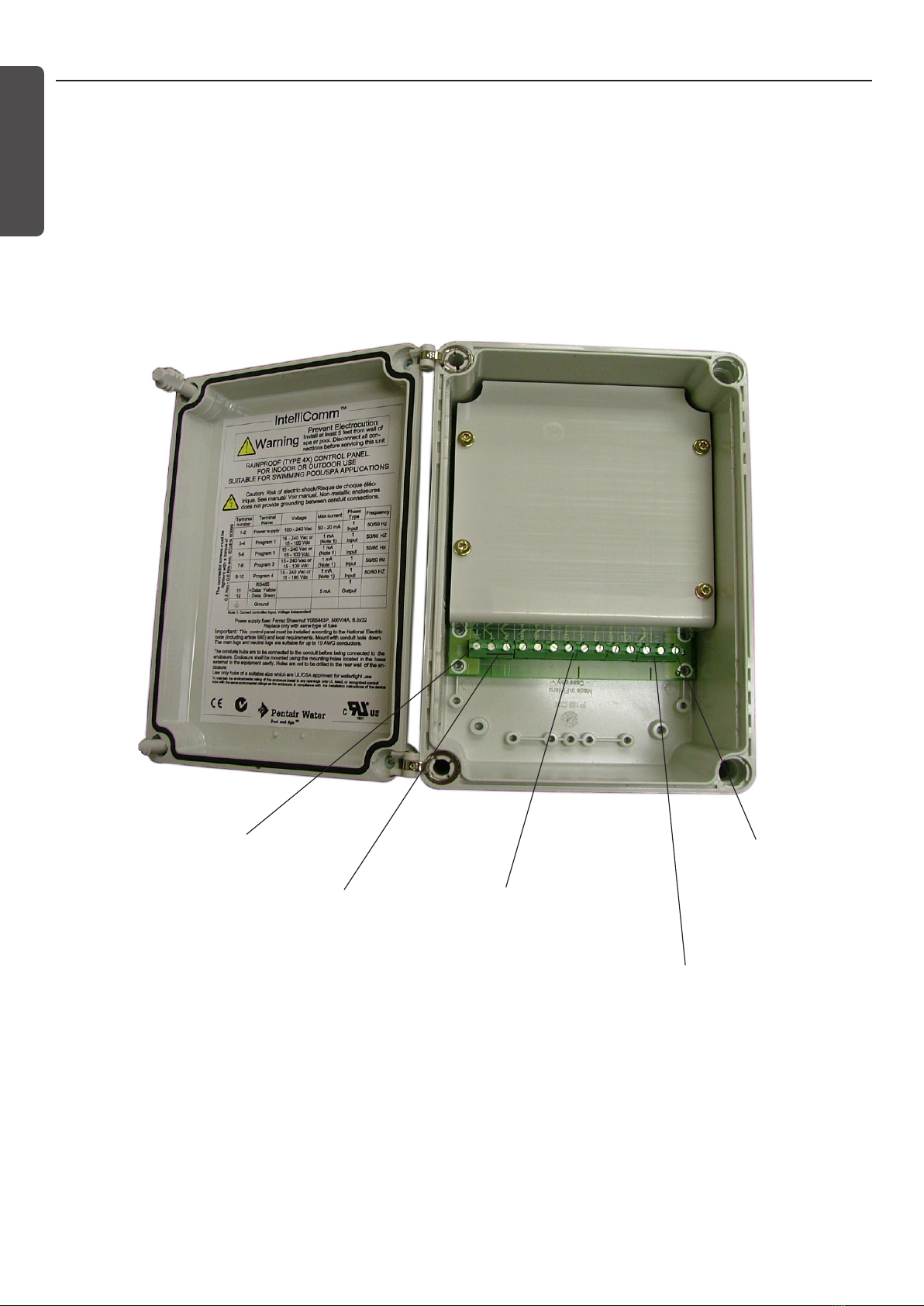
über einen FI-Schutzschalter anzuschließen. Die Anschlussleiste im Schaltkasten umfasst
eine grüne Klemme bzw. eine mit 'G', 'GR', 'Ground' oder'Grounding' (Erdung) beschriftete
Verbindungsklemme. Um die Gefahr von Stromschlägen zu vermeiden, muss diese Klemme
über einen Leiter vom selben Durchmesser wie die Leiterdrähte, über welche dieses Gerät
versorgt wird, an die Erdung des Stromkastens angeschlossen werden.
WARNUNG Um die Gefahr von Verletzungen zu vermeiden, dürfen Installation und
Wartung nur von qualizierten Fachkräften vorgenommen werden.
WARNUNG Um Verletzungen zu vermeiden, lassen Sie Kinder dieses Gerät nicht
benutzen, es sei denn sie werden dabei ständig beaufsichtigt.
ACHTUNG Die IntelliFlo-Pumpe darf nur für fest installierte Pools verwendet werden sowie
für Whirlpools und Warmwasserbecken, sofern sie entsprechend gekennzeichnet ist. Nicht
für nicht fest installierte Aufstellpools verwenden. Ein fest installierter Pool ist in den Boden
eingelassen bzw. fest auf dem Boden oder im Gebäude verankert, so dass er nicht beliebig
demontiert oder abgebaut werden kann. Aufstellpools hingegen sind so konzipiert, dass
sie jederzeit demontiert und eingelagert und bei Bedarf wieder komplett aufgebaut werden
können.
WICHTIGE SICHERHEITSHINWEISE
Abschnitt 1
Reihenfolge der Installationsschritte
Wir empfehlen, bei der Installation des IntelliComm-Steuerkasten folgende Reihenfolge zu
beachten:
1. Lesen der wichtigen Sicherheitshinweise: Lesen Sie diese
Hinweise bitte unbedingt durch.
2. Lesen der Beschreibung des IntelliComm: Lesen Sie sich die allgemeine
Produktbeschreibung durch.
3. Montieren des IntelliComm-Steuerkastens: Montieren Sie den IntelliComm-
Kasten.
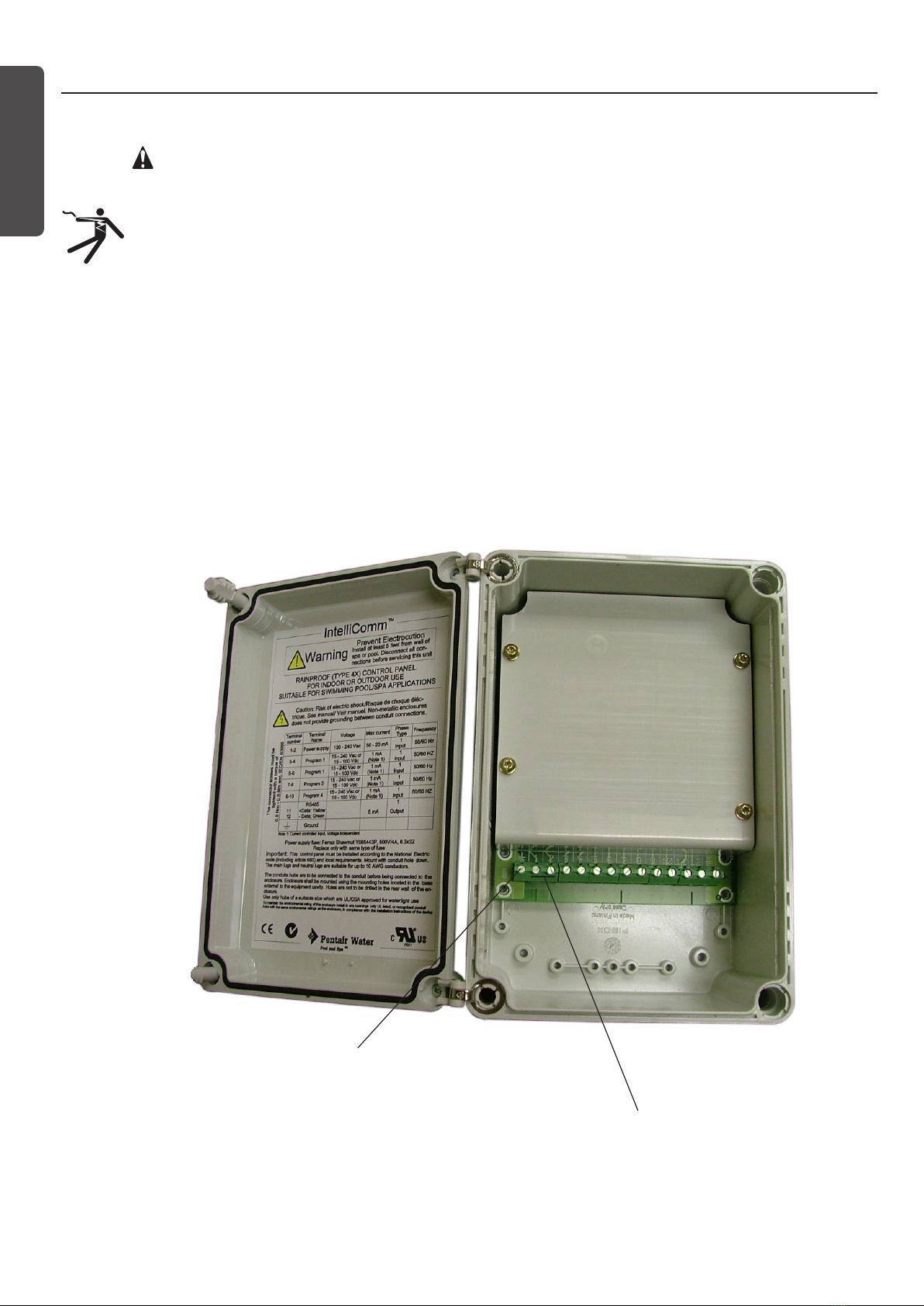
4. Anschließen der AC-Drähte an den IntelliComm: Schließen Sie die AC-
Drähte an die Klemmen 1 und 2 an.
5. Anschließen der Steuerkabel an den IntelliComm: Schließen Sie die
Drähte der Steuerkabel von Ausgangsgeräten wie z. B. automatische Steuerungen oder
Heizgeräten an die Klemmen 3 bis 10 an.
Deutsch
10

Deutsch
Drähte des IntelliFlo-Verbindungskabels
an Klemmen 11 und 12 anschließen
IntelliComm AC-Eingangskabel an
AC-Klemmen
1 und 2 anschließen
Erdungsklemme Erdungsklemme
Steuereingangskabel an
Klemmen 3 bis 10 anschließen
IntelliComm-Steuerkasten
Abschnitt 2
Inhalt des Sets
• IntelliComm-Steuerkasten
• Installations- und Bedienungsanleitung
• Zweiadriges RS-485 Verbindungskabel für die Verbindung zwischen IntelliComm-
Steuerkasten und IntelliFlo-Pumpe
Abschnitt 3
Der IntelliComm-Steuerkasten
Mit dem Pentair IntelliComm-Steuerkasten kann die IntelliFlo-Pumpe automatisch gesteuert
werden. Der IntelliComm umfasst vier Eingangsklemmenpaare. Diese Eingänge werden über
entweder 15V AC bis 240V AC oder 15V DC bis 100V DC vom Ausgangsgerät wie z. B. einer
automatischen Steuerung, einer Heizung oder einer Heizpumpe gesteuert. Über die Eingänge
des Geräts können die vier externen IntelliFlo-Steuerprogramme aktiviert werden. Ist mehr als
ein Eingang aktiv, hat das Programm mit der höheren Programmnummer Vorrang und wird an
die IntelliFlo-Pumpe übertragen.
Die IntelliFlo-Pumpe ist für jeden Eingang auf eine bestimmte Geschwindigkeit programmiert.
11

Abschnitt 4
Einbauen des IntelliComm-Kastens
Installieren Sie den IntelliComm-Kasten auf den zugehörigen Gehäuse-Pads in maximal 15,24
m Entfernung zur IntelliFlo-Pumpe. Lassen Sie rund um den Kasten ausreichend Abstand.
Achten Sie darauf, dass das Verbindungskabel von der IntelliFlo-Pumpe bis zum IntelliComm-
Kasten reicht. Der IntelliComm-Kasten kann an einer Wand oder einer anderen senkrechten
Fläche in einer Entfernung von maximal 15,24 m zur Steuerung angebracht werden.
ACHTUNG: Der IntelliComm-Steuerkasten muss in einer Entfernung von mindestens 2,44 m
zum Rand des Pools installiert werden.
Hinweis: Für nähere Hinweise zur Bedienung der IntelliFlo-Pumpe siehe Bedienungsanleitung
zur IntelliFlo 4-Pumpe.
Abschnitt 5
Montieren des IntelliComm-Kastens
1. Lösen Sie mit einem mittelgroßen Schlitzschraubendreher die beiden
Kunststoffschrauben am Gehäusedeckel und öffnen Sie diesen.
2. Halten Sie den Kasten an die Einbaustelle, z. B. eine gerade Wand oder einen
Pfosten. Zeichnen Sie die Position der Bohrlöcher an.
3. Bohren Sie vier Löcher mit einem 6-mm-Bohrer. Setzen Sie ggf. Dübel in die vier
Bohrlöcher ein und legen Sie sich vier Schrauben bereit.
4. Richten Sie den Kasten über den Bohrlöchern aus und stecken Sie die vier
Schrauben durch die Öffnungen im Gehäuse in die Dübel. Ziehen Sie die
Schrauben fest, um den Kasten an der Wand zu sichern.
Öffnung für Befestigungsschraube
Gehäuse-Verschlussschraube
Öffnung für Befestigungsschraube
Deutsch
12

Deutsch
Abschnitt 6
Anschließen der AC-Stromkabel an den IntelliComm-Steuerkasten
WARNUNG! WICHTIGE SICHERHEITSHINWEISE! LESEN SIE SICH VOR
BEGINN DER ARBEITEN FOLGENDE HINWEISE DURCH: Lesen Sie vor
jeglichen elektrischen Verkabelungsarbeiten die Sicherheitshinweise in
dieser Anleitung. Lesen und beachten Sie unbedingt die Sicherheitshinweise
auf Seite ii. Die Verkabelung darf nur von qualizierten Fachkräften
vorgenommen werden. Beim Umgang mit Elektrogeräten sind grundlegende
Sicherheitsmaßnahmen zu beachten, einschließlich folgender:
• Das Gerät muss geerdet werden. Das Gerät muss von einem qualizierten
Fachmann installiert und geerdet werden.
So schließen Sie das AC-Stromkabel an:
1. Schließen Sie die Drähte des AC-Stromkabels an die Klemmen 1 und 2 im
IntelliComm wie unten gezeigt an.
2. Erdung: Schließen Sie das Erdungskabel wie unten gezeigt an die Erdungsklemme
an. Die Erdung ist für die Sicherheit von Mensch und Gerät erforderlich.
3. Schließen Sie den Gehäusedeckel und ziehen Sie die beiden Kunststoffschrauben
fest.
AC-Stromkabel (100V AC bis 240V AC, 50/60 Hz) an
die AC-Klemmen 1und 2
Erdungsklemme
13

Abschnitt 7
Anschließen der IntelliComm-Steuerkabel
Der IntelliComm-Steuerkasten umfasst vier Eingangsklemmenpaare, die über entweder 15V
AC bis 240V AC oder 15V DC bis 100V DC vom Ausgangsgerät, wie z. B. einer automatischen
Steuerung, einer Heizung oder einer Heizpumpe, gesteuert werden. Es gibt vier externe
IntelliFlo-Steuerprogramme, die über die Eingänge des Geräts aktiviert werden können.
Hinweis: Der IntelliComm ist werksseitig so eingestellt, dass er stets eine Verbindung zu
Adresse 1 der Pumpe aufbaut.
Tabelle zur Zuordnung der Klemmen
Abschnitt 8
Elektrische Daten des IntelliComm-Steuerkastens
Leistungsaufnahme: Der IntelliComm benötigt weniger als 1 Ampere Strom. Die
Verbindungskabel zwischen Ausgangsgerät (z. B. automatische Steuerung, Heizgerät,
Heizpumpe) und Steuerkasten müssen am Ausgangsgerät mit einem Überspannungsschutz
versehen werden.
Eingänge von anderen Geräten: Der IntelliComm umfasst vier Eingänge, die als
Stromsensoren agieren und über entweder
15V AC bis 240V AC oder 15V DC bis 100V DC aktiviert werden.
Ausgänge an IntelliFlo-Pumpen: Der IntelliComm ist über ein zweiadriges serielles RS-485-
Kabel mit der IntelliFlo-Pumpe verbunden.
Hinweis: (*) Stromgesteuerter Eingang, spannungsunabhängig.
Klemmennummer Anschluss Spannung Max. Strom Phasentyp Frequenz
1-2 Stromversorgung 100 - 240V AC 100 mA 1 Eingang 50/60 Hz
3-4 Programm 1
15 - 240V AC
oder
15 - 100V DC
1 mA* 1 Eingang 50/60 Hz
5-6 Programm 2
15 - 240V AC
oder
15 - 100V DC
1 mA* 1 Eingang 50/60 Hz
7-8 Programm 3
15 - 240V AC
oder
15 - 100V DC
1 mA* 1 Eingang 50/60 Hz
9-10 Programm 4
15 - 240V AC
oder
15 - 100V DC
1 mA* 1 Eingang 50/60 Hz
11
12
RS-485
+ Daten: Gelb
- Daten: Grün
-5 bis +5V DC 5 mA 1 Ausgang k. A.
Erdung
Deutsch
14

Deutsch
Abschnitt 9
Anschließen des IntelliFlo-Verbindungskabels
Ein zweiadriges Verbindungskabel ist erforderlich, um die IntelliFlo-Pumpe mit dem
IntelliComm-Steuerkasten zu verbinden. Über dieses Kabel steuert der IntelliComm die
IntelliFlo-Pumpe. Die Belegung der Kontakte wird unten angezeigt.
Kontaktbelegung des IntelliFlo-Verbindungskabels
Hinweis: Kontakte 1 bis 5 sind nicht belegt.
Kontakt 6 (grün) RS-485 (N) Kontakt 7 (gelb) RS-485 (P)
15

© 2008 Pentair Water Pool and Spa, Inc. Alle rechten voorbehouden
Dit document kan worden gewijzigd zonder kennisgeving
Handelsmerken en disclaimers: IntelliComm, IntelliFlo en het Pentair Water Pool en Spa-logo zijn handelsmerken
van Pentair Water Pool and Spa, Inc. Het is mogelijk dat andere handelsmerken en handelsnamen worden gebruikt in
dit document om te verwijzen naar de entiteiten die aanspraak maken op de merken en de namen of hun producten.
Pentair Water Pool and Spa, Inc. wijst elk eigendomsbelang in merken en namen van anderen af.
Klantendienst
HERENTALS, BELGIUM (8.30 uur tot 16.30 uur) CET
Telefoon: + 32 (0) 14 25 99 11
Website: www.pentairpooleurope.com
Conformiteitsverklaring
We verklaren, op eigen verantwoordelijkheid, dat het product dat beschreven wordt in dit document
en waarop deze informatie betrekking heeft, overeenstemt met de vereisten van de Richtlijn van de
Raad 98/
37/EEG
Patenten aangevraagd in VS
Producent: Pentair Water Pool and Spa, Inc.
Belangrijke veiligheidsvoorzorgen 17
Sectie 1: Installatiestappen - samenvatting 17
Sectie 2: Inhoud kit 17
Sectie 3: IntelliComm Communication Center 18
Sectie 4: De IntelliComm behuizing installeren 19
Sectie 5: De IntelliComm behuizing bevestigen. 19
Sectie 6: AC stroomkabels aansluiten op IntelliComm 20
Sectie 7: IntelliComm systeembekabeling 21
Sectie 8: IntelliComm elektrische specicaties 21
Sectie 9: De IntelliFlo verbindingskabel aansluiten 22
Inhoud
Nederlands
16

WAARSCHUWING Lees en volg alle veiligheidswaarschuwingen en -instructies in deze
gids voordat u dit product installeert. Als deze waarschuwingen en instructies niet worden
opgevolgd, kan dit ernstige letsels, overlijden of materiële schade veroorzaken.
OPGELET wanneer u het IntelliComm communicatiecentrum met de IntelliFlo
pomp gebruikt, is het aanbevolen de IntelliComm stroomcentrale aan te sluiten op een
verliesstroomschakelaar om het circuit te beschermen. Een groene terminal (of een
kabelconnector gemarkeerd met "G", "GR", "Ground" of "Grounding") is voorzien in het
aansluitcontactencompartiment in de transformatorkast van de elektriciteitcentrale . Om het
risico op elektrische schok te verminderen, dit aansluitcontact of connector aansluiten op de
aardingsterminal van uw elektrisch bedienings- of voedingspaneel met een geleider die qua
afmeting overeenstemt met de circuitgeleiders die deze installatie voeden.
WAARSCHUWING Om het het risico op letsels te verminderen, de installatie of bediening
alleen laten uitvoeren door een gekwaliceerde zwembadspecialist.
WAARSCHUWING Om het risico op letsels te verminderen, mogen kinderen dit product
niet gebruiken, tenzij ze permanent onder streng toezicht staan.
OPGELETDe IntelliFlo-pomp is voor gebruik in permanent geïnstalleerde zwembaden
en kan ook worden gebruikt in warmwaterbaden en spa's indien dat zo is aangegeven. Niet
gebruiken voor opbergbare zwembaden. Een permanent geïnstalleerd zwembad is in of op
de vloer of in een gebouw geïnstalleerd zodat het niet gemakkelijk kan worden gedemonteerd
voor opslag. Een opbergbaar zwembad is zo geconstrueerd dat het gemakkelijk kan worden
gedemonteerd voor opslag en opnieuw gemonteerd in zijn originele vorm.
BELANGRIJKE VEILIGHEIDSVOORZORGEN
Sectie 1
Installatiestappen - samenvatting
De aanbevolen installatiestappen voor het IntelliComm Communication Center zijn als volgt:
1. Lees de belangrijke veilgheidsinstructies: Lees deze belangrijke
informatie.
2. Lees het IntelliComm Overzicht: Lees het productoverzicht.
3. IntelliComm installeren: De IntelliComm behuizing installeren.
4. De AC stroomkabels aansluiten op IntelliComm: AC stroomkabels
aansluiten op aansluitcontacten 1 en 2.
5. De besturing-ingangskabels aansluiten op IntelliComm:
Besturingsinput aansluiten op aansluitcontacten 3 tot 10 van broncomponenten zoals
automatiseringscontrollers of verwarmingselementen. Sectie 2
Inhoud kit
• IntelliComm Communication Center
• IntelliComm Installatiegids (deze gids)
• Twee-draads RS-485 verbindingskabel. Gebruikt voor de verbinding van de
IntelliFlo-pomp naar IntelliComm.
Nederlands
17

Sluit IntelliFlo verbindingskabels aan op
aansluitcontacten 11 en 12
Sluit inkomende IntelliComm
stroomkabels aan op AC aansluit-
contacten
1 en 2
Aardingsklem Aardingsklem
Sluit besturingsinputkabels aan op
aansluitcontacten 3 tot 10
IntelliComm Communication Center
Sectie 3
IntelliComm Communication Center
De Pentair IntelliComm communicatiecentrale biedt automatische controle op de IntelliFlo-
pomp. De IntelliComm biedt vier paar input-aansluitcontacten. Deze inputconnectoren worden
gevoed door ofwel 15 VAC tot 240 VAC ofwel 15 VDC tot 100 VDC van de broncomponent
zoals een automatiseringscontroller, verwarmingselement of warmtepomp. Met behulp van de
input van deze component, kunnen de vier externe IntelliFlo besturingsprogramma's in werking
worden gesteld. Indien meer dan één input actief is, wordt het hoogste programmanummer
doorgegeven aan de IntelliFlo-pomp.
De IntelliFlo-pomp is geprogrammeerd om voor elke input op een specieke snelheid te
draaien.
Nederlands
18

Sectie 4
De IntelliComm behuizing installeren
Installeer de IntelliComm behuizing bij het bedieningspaneel op maximum 15.24 m (50ft.)
van de IntelliFlo-pomp. Laat voldoende ruimte aan alle zijdes van de behuizing. Zorg dat de
verbindingskabel van de IntelliFlo-pomp tot op de plaats van de behuizing van de IntelliComm
kan komen. De IntelliComm-behuizing kan aan een muur worden bevestigd of een vlak
verticaal oppervlak tot 15.24 m (50ft) van het celbesturingsapparaat verwijderd.
OPGELET: De IntelliComm communicatiecentrale moet op meer dan 2.44 m (8 ft.) van de
randen van het zwembad worden geïnstalleerd.
Opmerking: Voor bedieningsinstructies van de IntelliFlo 4-pomp, zie de Gebruikersgids
IntelliFlo 4 . Sectie 5
De IntelliComm behuizing bevestigen.
1. Met behulp van een middelgrote platte schroevendraaier, de twee plastic schroeven
losdraaien aan de voorzijde en de afdekplaat aan de voorzijde openen.
2. De behuizing bevestigen op een vlak oppervlak zoals een muur of een zuil.
Markeer de plaatsen voor de gaten van de bevestigingsschroeven.
3. Boor vier gaten van 6 mm (1/4 inch). Breng indien nodig pluggen aan en een
schroef voor elk behuizingsgat.
4. Plaats de behuizing over de gaten en draai de vier bevestigingsschroeven in de
schroefgaten van de behuizing. Draai de vier schroeven vast om de behuizing vast
te zetten.
Toegangsgat bevestigingsschroef
Schroef die behuizing vasthoudt
Toegangsgat bevestigingsschroef
Nederlands
19

Sectie 6
AC stroomkabels aansluiten op IntelliComm
LET OP! BELANGRIJKE VEILIGHEIDSVOORZORGEN. LEES VOOR U
BEGINT HET VOLGENDE: Lees alle veiligheidsvoorzorgen in deze gids voor
u elektrische bekabeling aanlegt. Lees en volg alle veiligheidsinstructies op
pagina ii. Bekabeling dient alleen uitgevoerd te worden door gekwaliceerde
vakmensen. Bij gebruik van elektrische producten, altijd de basisvoorzorgen
in acht te nemen, waaronder de volgende:
• Aarding is vereist. De eenheid dient geïnstalleerd te worden door een
gekwaliceerde onderhoudsman en geaard.
Om de AC stroomkabels aan te sluiten op IntelliComm:
1. Sluit de AC hoofdstroomkabels aan op de IntelliComm AC aansluitcontacten
nummer 1 en 2 zoals hieronder afgebeeld.
2. Aarding: Verbind inkomende AARDING-kabel met het aardingaansluitcontact
zoals hieronder afgebeeld. Aarding is noodzakelijk om persoonlijke veiligheid en
veiligheid van de uitrusting zeker te stellen.
3. Sluit de voorplaat en zet de twee voorplaatschroeven vast.
Sluit toevoer AC (100 VAC tot 240 VAC 50/60 Hz) aan
kabels naar AC aansluitcontacten 1en 2
Aardingsklem
Nederlands
20
Table of contents
Languages:
Popular Conference System manuals by other brands

Cisco
Cisco Quick Set C20 Installation sheet

Samsung
Samsung iDCS500 manual

Polycom
Polycom SoundStation Installation instructions and user guide

DSG Technology
DSG Technology InterPBX Blaze5000 Installation and configuration guide

Adena
Adena RADA A-PT01 Quick installation guide

Omron
Omron C200HW-COM01 Operation manual