LINCOLN LISTED
38h9 U.S. Patent
IND. CONT. EQ. Series “B”
Model 84530
SYSTEM SENTRY™
APENTAIR AIRCOMPANY
SENSOR CONTROLLER -EXTERNAL SCAN
OWNER/OPERATOR MANUAL
It isthe responsibility of the Owner/Operator to properly use and maintain this equipment
The Instructions and Warnings contained in this manual shall be read and understood by the Owner/Operator prior to
operating this equipment
It isthe responsibility of the Owner/Operator to maintain the Iegibility of all Warning and Instruction labels
The Owner/Operator shall retain this manual for future reference to important Warnings, Operating and Maintenance
Instructions.
CONTENTS PAGE
Description 1
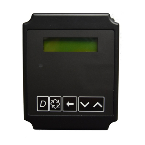
Liquid Crystal Display 2
Programming Mode 2
Run Mode 4
Alarm Messages 4
Installation of Sensors 5Electrical shock hazard. Do Not subject sensor
Field Connections 6Turn off and lock out power bodies to pressure greater
Service Parts 7before opening enclosure. than 6,000 PSIG.
Specifications 8
System Accessories 8
DESCRIPTION
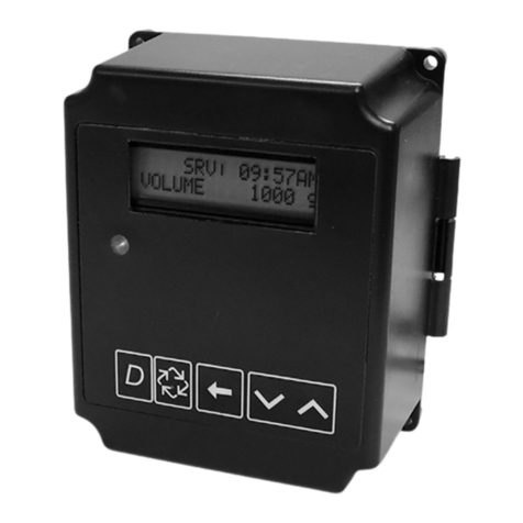
When programmed as a Sensor Controller, Model 84530 wiII
verify delivery of Iubricant into abearing
The Sensor Controller can only detect faults which occur
between the sensor (located in the delivery Iine at the bearing
lube inlet) and the flow source. Continuous flow or no flow during
the delivery cycle are both signaled as a fault by this system.
Aminimum of 30 seconds between the end of one flow to the
beginning of the next flow is required for detection.
Sensors wiII function at any pressure up to 6,000 PSIG. The
temperature of the material which is to be delivered past the
sensors must be between 32° Fto 145° Ffor effective operation
of the system. Viton seals and checks in the sensors allow their
use in systems distributing synthetic lubricants as well as
petroleum based lubricants. For reliable operation, sensors
can only be used with Model 84530.
When power is turned on to the Controller and aLube
cycle is immediately initiated, asensor fault may occur
due to the sensors not having enough time to warm. It is
recommended that the Delay Alarm be set at 2in order to
prevent anuisance alarm.
An external switch (contact closure) or an external signal
(120/230 VAC) wiII initiate ascan period (amount of time that
the sensors are scanned for lube flow). The scan period IS the
time that the external switch IS closed.
When the external switch closes the amber Iight turns on and
the timer on the display begins timing up from zero, indicating
the amount of time the external switch has been closed. If the
sensors are satisfied while the external switch is closed the
amber Iight wiII turn off. When the external switch opens the
timer on the display IS reset to zero and begins timing up again,
indicating how long since the last scan period
If the sensors are not satisfied while the external switch is
closed the following will happen:
Amber Iight on door remains on.
The timer on the screen is reset to zero and begins timing up
Indicating when the last scan period took place.
If, after thirty seconds following the external switch opening,
the sensors still have not been satisfied and the delay alarm
counter has reached its set value the following will happen
Red light on door turns on
Alarm relay contact closes
Alarm message wiII alternate with Scan Timer on
enclosure door
If lube flow takes place while the external switch iS open, the
fault wiII be cleared However, the next time the external switch
closes the amber Iight wiII not turn on
Due to the numerous options available, the customer can field
program the controller to match the system requirements
Programming iseasily accomplished by following auser friendly
menu displayed on the LCD and pressing the active buttons
beneath the display An internal jumper pin provides security
against unauthorized programming All programmed parameters
are automatically stored in anonvolatile memory AReview
Screen can be easily activated to display what has been
programmed Programmed values can be changed
whenever necessary
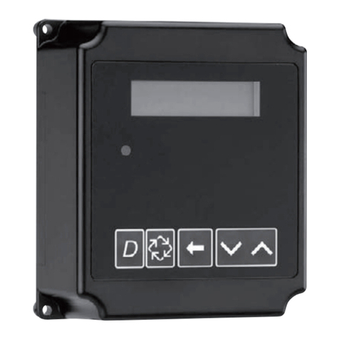
There are three Iights on the enclosure door to Indicate the
status of the system
Green -Power On
Amber -Sensors are waiting to be satisfied.
Red -Alarm
If an alarm occurs, the cause of the alarm wiII appear on the
LCD Turning off power tothecontroller when in alarm will reset
the alarm
The LCD is capable of displaying the following messages
Amount of elapsed time since the External switch opened
Amount of elapsed time that the External switch has
been closed
Number of times each bearing has received lube
Indicates what sensor did not receive lube
Indicates what sensor has abroken wire
Indicates what sensor has ashorted wire
LINCOLN One Lincoln Way Copyright 1993 Section -C8
St.Louis, Missouri 63120-1578 Printed inU.S.A.
APENTAIR COMPANY (314)679-4200 Page -247-5A
JAN-93 FORM 402435
