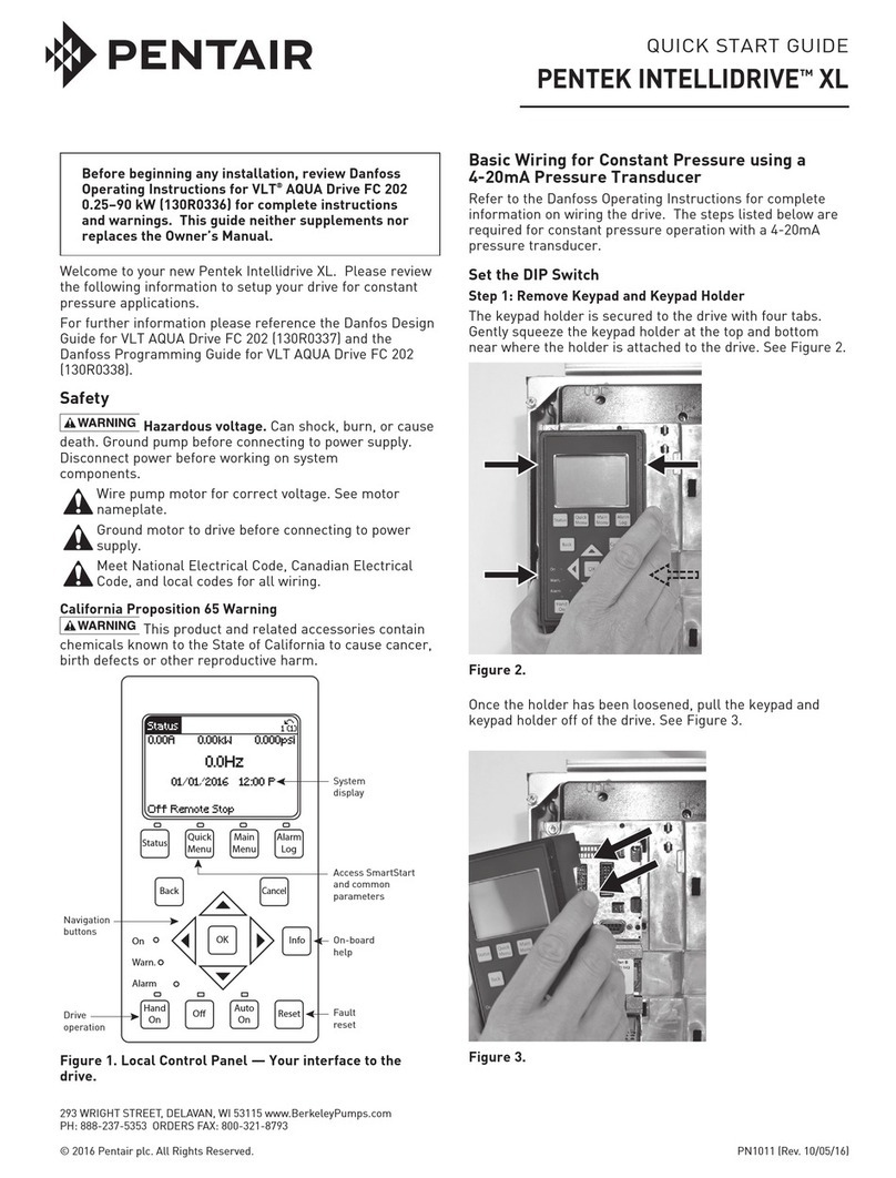
Ce guide de démarrage rapide ne complète pas et ne remplace pas le manuel
d’installation.
1 EMPLACEMENT DE MONTAGE
•Surlemur-NEMA1:INTÉRIEURUNIQUEMENT;NEMA3R:Extérieurcouvert
•Montezlemécanismeàlaverticaleetaussiprèsquepossibledupanneauàdisjoncteurprincipal.
•Laissezundégagementde7,6cm(3po)autourdumécanismepourpermettresonrefroidissement.
2ACHEMINEMENT DU CÂBLE
•PourquelesboîtiersNEMA3Rconserventleurhomologation,lescâblesdoiventêtreacheminésdansunconduit
étancheauxliquidesavecdesconnecteurségalementétanches.
•L’alimentationprovenantdupanneauàdisjoncteurdoitsesituerà20,3cm(8po)desfilsdumoteuretdetoutautre
câblagedomestique.Maintenezl’écartde20,3cm(8po)lorsd’uncroisementavecd’autresfils.
•Faitessecroisertouslescircuitsdedérivationà90°.
•Lesfilsdumoteurdoiventsortirdubâtimentdèsquepossible.
3RACCORDEMENT DU PANNEAU À DISJONCTEUR AU MÉCANISME
•N’effectuezpasderaccordementàunpanneausecondaire,seulementaupanneauàdisjoncteurprincipal.
•Mettezl’arrièredumécanismeàlaterredirectementsurlaterredubâtiment(c’est-à-direlaterredupanneauà
disjoncteur,allantàlatigedemiseàlaterredusystème).
•Utilisezuncircuitdedérivationdédiéde230V,directementàpartirdupanneauàdisjoncteur:Disjoncteurde15A
pourlemodèlePPC7-1-7A3;Disjoncteurde30ApourlemodèlePPC7-1-13A2.
4RACCORDEMENT DU MÉCANISME AU MOTEUR
•Raccordezlesfilsdumoteurdansl’ordreillustré.
•Connectezlaterredumoteuràlabornedemiseàlaterredel’onduleur,commeindiqué.
•Mettezlemoteuràlaterreauniveaudelatêtedupuits.
•Raccordezlemécanismeaumoteuravecunfildeterredédié.Attachezlesfilsdeterreetdumoteur.
5RACCORDEMENT DU CÂBLE DE TRANSDUCTEUR
•Raccordezlecâbledutransducteurcommeillustré.
•Nebougezpaslesfilsvolantsinstallésàl’usine.
•Nettoyezleboîtier:ENLEVEZTOUSLESDÉBRIS!
NOTE:Avantderaccorderlapompeausystème,pompezl’eaudupuitspourlenettoyer.Vérifiezqueletransducteurest
raccordéaumécanismeetmesureunepressionde0lb/po≈.Diminuezlerefoulementdelapompepourréduirelacharge
appliquéeaumoteur.
Unefoislepuitspropre,installezlaplomberie.
6PLOMBERIE/RÉSERVOIR
•Lapréchargeduréservoirdoitreprésenter70%delapressiondeconsigne(42lb/popourunpré-réglagede60lb/po).
7MISE EN MARCHE! Lapompepeutêtredémarrée.Lesparamètrespeuventêtre
réglésaveclapompeenfonctionnement.
NOTE : Vérifieztouslesraccordementsavantdemettrelemécanismeenmarche.
RÉGLAGE DES PARAMÈTRES AU DÉMARRAGE
NOTE :
Leparamètre9estutilisécommeexemple.Réglezlesautresparamètresdelamêmemanière.Pourmodifierla
pressiondeconsignedel’eau(paramètre133),consultezlemanueld’installation.
Étape 7.1.A : Appuyezunefoissur«MODE»pourafficherlesparamètres.
Étape 7.1.B :Tournezleboutonjusqu’àcequeP.9(paramètre9)s’affiche.
Étape 7.2.A :Appuyezsur«SET»(Régler)pourafficherlavaleurdeconsignepardéfautduparamètresélectionné.
Étape 7.2.B : Tournezleboutonpourajusterlavaleurdeconsigne(consultezletableauci-dessus).Relâchezleboutonet
appuyezsur«SET»(Régler).L’affichagealterneentrelenumérodeparamètreetlanouvellevaleurdeconsigne.
Étape 7.2.C :Répétezl’opérationpourP.22(2HPuniquement).
Étape 7.3.A :Appuyezdeuxfoissur«MODE»pourreveniràl’affichagestandard(Hz).
Étape 7.3.B :Appuyezsur«SET»(Régler)pourafficherl’intensitéenampères.
Étape 7.3.C :Appuyezdenouveausur«SET»(Régler)pourafficherlapression(lb/po≈).Continueràappuyersur
«SET»(Régler)faitdéfilerlestroisaffichages(Hz,A,lb/po≈).
NOTE :Pourverrouilleroudéverrouillerlesréglages,affichertouslesparamètres,oupourobtenirdel’informationdétaillée,
consultezlemanueld’installation.
8REMETTEZ LE COUVERCLE DU MÉCANISME EN PLACE :Lesystèmeestopérationnel.
Esta Guía de Inicio Rápido no suplementa ni sustituye la Guía de Instalación.
1LUGAR DE MONTAJE
•Enlapared-NEMA1:SÓLOENINTERIORES;NEMA3R:Enexterioresprotegidos.
•ColoqueelmecanismoCFVenposiciónverticalytancercacomoseaposibledeltableroprincipaldedisyuntores.
•Deje3”deespaciolibrealrededordelCFVparaenfriamiento.
2ACOMODAMIENTO DEL CABLE
•LoscablesalascajasclasificadasNEMA3Rdebenestarenconductosyconectoresimpermeablesparamantener
laclasificación3R.
•LaentradadesdeelTablerodeDisyuntoresdebeserde8pulgadasdesdeelcableadodelmotoryde8pulgadas
desdetodootrocableadodelacasa.Mantengalaseparaciónde8pulgadascuandocruceotroscables.
•Crucetodoslosramalesa90°.
•Loscablesdelmotordebensalirdeledificiotanprontocomoseaposible.
3CONEXIÓN DEL TABLERO DE DISYUNTORES AL MECANISMO CFV
•Nocableeauntablerosecundario-sóloaltableroprincipaldedisyuntores.
•ConectelaparteposteriordelCFVatierramediantelapuestaatierradeledificio(esdeciralsistemadepuestaa
tierradesdeeltablerodedisyuntores,yendoalabarraatierradelsistema).
•Useunramaldedicadode230Vdirectamentedesdeeltableroprincipaldedisyuntores:disyuntorde15amppara
elModeloPPC7-1-7A3;disyuntorde30ampparaelModeloPPC7-1-13A2.
4CONEXIÓN DEL MECANISMO CFV AL MOTOR
•Conectelosconductoresdelmotorenelordenilustrado.
•Conectelapuestaatierradelmotoralborneatierradelinversor,segúnseilustra.
•Conecteelmotoratierraconelcabezaldelpozo.
•ConecteelCFVatierraconelmotorconcableatierradedicado;ateloscablesatierraylosdelmotor.
5CONEXIÓN DEL CABLE DEL TRANSDUCTOR
•Conecteelcabledeltransductorsegúnseilustra.
•Noperturbeloscablesdeempalmeinstaladosdefábrica.
•Limpielacaja:¡NODEBEESTARSUCIAOCONESCOMBROS!
NOTA:Antesdeconectarlabombaalsistema,extraigaelaguadelpozoparalimpiarlo.Verifiquequeeltransductor
estéconectadoalCFVytengaunapresiónde0librasporpulgadacuadrada(PSI).Disminuyalavelocidaddela
descargadelabombaparareducirlacargasobreelmotor.Unavezqueelpozoestélimpio,continúeconlas
conexionesdeplomería.
6PLOMERÍA / TANQUE
•Lapre-cargadeltanquedebeestara70%delpuntodepresiónpreconfigurado(42psiparaunapreconfiguración
de60psi).
7¡LISTO PARA FUNCIONAMIENTO! Sepuedeencenderlabomba;losparámetrossepueden
configurarconlabombaenmarcha.
NOTA: InspeccionetodaslasconexionesdeloscablesantesdeencenderelCFV.
CONFIGURE LOS PARÁMETROS AL INICIO
NOTA:
Elparámetro9seusacomoejemplo.Configureotrosparámetrosdelamismamanera.ParareconfigurarelPunto
deReferenciadelaPresióndelAgua(Parámetro133),consultelaGuíadeInstalación.
Paso 7.1.A: Oprima‘MODE’(MODO)paravisualizarlosparámetros.
Paso 7.1.B:GirelaperillahastaquelavisualizaciónmuestreP.9(Parámetro9).
Paso 7.2.A:Oprima‘SET’(CONFIGURAR)paravisualizarelpuntodereferenciapordefectodel
parámetroseleccionado.
Paso 7.2.B:Girelaperillaparaajustarelpuntodereferencia(consultelaillustraciónarriba).Sueltelaperillay
oprima‘SET’.LavisualizaciónalternaráentreelNúmerodelParámetroyelnuevopuntodereferencia.
Paso 7.2.C:RepitaparaP.22(2HPsolamente)
Paso 7.3.A:Oprima‘MODE’dosvecespararegresaralavisualizaciónestándar(Hz).
Paso 7.3.B:Oprima‘SET’paravisualizarlosAmperios.
Paso 7.3.C:Oprima‘SET’nuevamenteparavisualizarlaPresión(PSI).Continúeoprimiendo‘SET’parapasarporestas
tresvisualizaciones(Hz,Amperios,PSI).
NOTA:Paratrabaroabrirlasconfiguraciones,visualizartodoslosparámetrosoparaobtenerinformacióndetallada,
consultelaGuíadeInstalación.
8VUELVA A COLOCAR LA TAPA DEL CFV - Elsistemaestálistoparafuncionar.
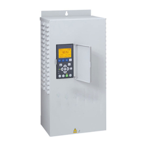
Guidededémarragerapidedumécanismed’entraînement
àfréquencevariabledelasériePPC7dePENTEK
Avant de commencer, vérifiez que vous avez le modèle qui convient à votre installation :
Les puissances de 1/2, 3/4 et 1 HP requièrent un modèle PPC7-1-7A3-1-A (NEMA 1) ou PPC7-1-7A3-3-A (NEMA 3R).
Les puissances de 1-1/2 et 2 HP requièrent un modèle PPC7-1-13A2-1-A (NEMA 1) ou PPC7-113A2-3-A (NEMA 3R).
Controldefrecuenciavariable(“CFV”)
PENTEKSeriePPC7-GuíadeInicioRápido
Antes de comenzar, verifique que tenga el modelo correcto para su instalación:
1/2, 3/4, y 1 HP usan Modelos PPC7-1-7A3-1-A (NEMA 1) o PPC7-1-7A3-3-A (NEMA 3R)
1-1/2 y 2 HP usan Modelos PPC7-1-13A2-1-A (NEMA 1) o PPC7-1-13A2-3-A (NEMA 3R)
1ACHEMINEMENT DU CÂBLE
ACOMODAMIENTO DEL CABLE
2
Utilisez des cosses
ouvertes ou faites des
boucles avec les câbles
Use bornes abrochables
o haga bucles con el cable
Fils d’entrée provenant du
panneau à disjoncteur
Cables de entrada desde el
tablero de disyuntores
3
Alimentation
d'entrée
provenant
du filtre
Alimentación
desde el filtro Fil volant de terre
Cable de empalme a tierra
Bornes
de terre
Bornes
a tierra
Vert rayé jaune
Verde con raya
amarilla
Fils du moteur
Conductores
del motor
4
90°
6
Risque de choc électrique si le mécanisme est raccordé au câblage de
l’alimentation électrique avant que le boîtier n’ait été accroché. Risque de choc électrique
si le mécanisme est raccordé au câblage de l’alimentation électrique avant que le boîtier
n’ait été accroché. Accrochez toujours le boîtier du mécanisme avant d’y connecter des fils.
Risque de choc électrique si le mécanisme est manipulé, entretenu ou
réparé avec des mains mouillées ou humides. Veillez toujours à ce que vos mains soient
sèches avant de manipuler le mécanisme. Effectuez tous les réglages des boutons et les
opérations de saisie avec les mains sèches.
Risque de choc électrique. Ne changez pas le ventilateur lorsque le
mécanisme est sous tension.
Risque d’incendie en cas d’installation avec une protection par
disjoncteur incorrecte ou inadéquate. Pour vérifier la protection dans le cas d’une
défaillance interne au mécanisme, installez celui-ci sur un circuit de dérivation indépendant,
, sans aucun autre appareil et protégé par un disjoncteur de 15 A (modèle PPC7-1-7A3, - 1/2
à 1 HP) ou de 30 A (modèle PPC7-1-13A2, 11/2 et 2 HP.
Risque d’explosion de composant et d’incendie si les câbles sont
mal installés ou qu’une mauvaise tension est appliquée. Utilisez uniquement la tension
spécifiée pour chaque borne. Raccordez les câbles aux bornes appropriées, en suivant les
indications de ce guide.
Avertissement lié à la Proposition 65 de la Californie
Ce produit et les accessoires connexes contiennent des produits
chimiques reconnus dans l’État de la Californie comme pouvant provoquer des cancers, des
anomalies congénitales ou d’autres dangers relatifs à la reproduction.
Peligro de choque eléctrico si el CFV está conectado
a un cable de alimentación eléctrica antes de colgar la caja. Peligro de choque eléctrico
si el CFV está conectado a un cable de alimentación eléctrica antes de colgar la caja.
Siempre cuelgue la caja del CFV antes de conectar los cables al mismo.
Peligro de choque eléctrico si el CFV se manipula o se repara con
manos húmedas o mojadas. Siempre asegúrese de que sus manos estén secas antes de
trabajar con el CFV. Realice todas las configuraciones del cuadrante y las operaciones de
modulación con las manos secas.
Peligro de choque eléctrico. No cambie el ventilador de refrigeración
mientras la corriente eléctrica del CFV esté activada.
Peligro de incendio si se instala con un disyuntor de protección
incorrecto o inadecuado. Para verificar que esté protegido en caso de una falla interna en
el CFV, instale el CFV en un ramal eléctrico independiente protegido por un disyuntor de 15
amperios (Modelo PPC7-1-7A3, 1/2 a 1 HP) o de 30 amperios (Modelo PPC7-1-13A2, 1-1/2 y
2 HP), sin ningún otro aparato en el circuito.
Peligro de explosión de los componentes y de incendio si los cables
se conectan en forma incorrecta o si se aplica la tensión incorrecta. Aplique sólo la
tensión especificada para cada borne. Conecte los cables a los bornes correctos según se
especifica en esta guía.
Advertencia de la Proposición 65 de California
Este producto y accesorios relacionados contienen sustancias químicas
reconocidas en el Estado de California como causantes de cáncer, malformaciones
congénitas y otros daños al sistema reproductivo.
RÉGLAGE DES PARAMÈTRES AU DÉMARRAGE
CONFIGURAR LOS PARÁMETROS AL INICIO
HP /
H.P. N° de paramètre /
Parámetro No. Réglage /
Configurar a
1/2,1-1/2 Aucun/Ninguno Défaut/Defecto
3/4,1 9 7,3
29
22
12,6
62
Étape 7.1 / Paso 7.1
7
Étape 7.2 / Paso 7.2 Étape 7.3 / Paso 7.3
REMISE EN PLACE DU COUVERCLE DU MÉCANISME /
VOLVER A COLOCAR LA TAPA DEL CFV:
Lesystèmeestopérationnel.
Elsistemaestálistoparafuncionar.
8
5
