Borne
removible
(jalar hacia
abajo)
01+ 01+ I1+ I1- I2+ I2- V+ V- AI+ AI- P N SD CARD
Conexiones del cable
del transductor
Motor sumergible: Trifásico/Trifilar. Monofásico siga los colores indicados arriba.
Motor sumergible: Monofásico/Bifilar, conecte a Y y B, en cualquier orden.
Motores sobre la superficie: L1 a R, L2 a Y, L3 a B; verificar la rotación
Tornillo a tierra
de salida
Conexiones de
energía de entrada
Tornillo a tierra
de entrada
Rojo
Amarillo
Negro
Tierra de salida
Tierra de
entrada
Conexiones del motor
Rojo a AI+
Negro a AI–
Tornillo/escudo del cable verde
Borne
amovible
(en tirant)
Cuadro 1: PENTEK®Amperios del Factor de Servicio
Tipo de
motor
Número de pieza
PENTEK
Clasificación
nominal
@ 230V
Factor de
servicio
Amperios
HP
Bifilar(2)
P42B0005A2-01 1/2 4.7
P42B0007A2-01 3/4 6.2
P42B0010A2-01 1 8.1
P42B0015A2-01 1-1/2 10.4
P42B0005A2-02 1/2 5.1
P42B0007A2-02 3/4 6.1
P42B0010A2-02 1 8.0
P42B0015A2-02 1 1/2 10.6
CS/CR
Trifilar(3)
P43B0005A2-01 1/2 4.8
P43B0007A2-01 3/4 6.0
P43B0010A2-01 1 7.3
P43B0015A2-01 1-1/2 10.9
P43B0005A2-02 1/2 4.5
P43B0007A2-02 3/4 5.7
P43B0010A2-02 1 6.8
P43B0015A2-02 1 1/2 10.7
Trifásico(3)
P43B0005A3 1/2 2.9
P43B0007A3 3/4 3.9
P43B0010A3 1 4.7
P43B0015A3 1-1/2 6.1
P43B0020A3 2 7.6
P43B0030A3 3 10.1
P43B0050A3 5 17.5
Arranque Inicial: Incio del Sistema
• Abrirlasllavesenlosextremosdelastuberíasparadejarescaparelairedurantela
presurización.Oprimir“Auto Start”(Inicioautomático).
• ElMecanismodeAccionamientopasaráa“AutoLineFill”(Llenadodetubería
automático).
• Cerrarlasllavesenlosextremosdelastuberíasdespuésdehaberdejadoescapar
todoelaire.
• CuandoelTransductordetecte10PSI,elMecanismodeAccionamientopasaráal
MododePresiónConstanteymantendrálas60PSI.
• Siserequiereunapresióndiferente,utilicePSI Presetparacambiarelpuntode
referencia.
6
Arranque Inicial: Bombear Para Vaciar el Pozo
Dirigirladescargadelabombahaciaunlugaradecuadoquenoestéconectadoalsistema.
Oprimir“Pump Out”(Vaciarporbombeo).Labombafuncionaráa45Hz.Ajustedefrecuencia
segúnseaapropiado:
A. Oprimir“Enter.”
B. Cambiarelvalordefrecuencia.
AVISO Lasinstalacionessobreelsuelorequierenunaoperaciónde60Hzparacebar.Después
dehabercebado,ajustelafrecuenciacomocorresponda.
C. Oprimir“Enter” nuevamente.ActivarelMecanismodeAccionamientoenestemodohasta
queladescargadelpozoseaclaraytransparente,luegooprimir“STOP”paradetenerel
MecanismodeAccionamiento.
Peligro de explosión.Puedeprovocarlesionesgraves,dañosmaterialesomuerte.Enel
modoVaciarporBombeo,labombamarchaaunavelocidadconstante.Unarestriccióndeflujo
puedeprovocarunapresiónmuyalta.Nosedeberestringirelflujo.
4
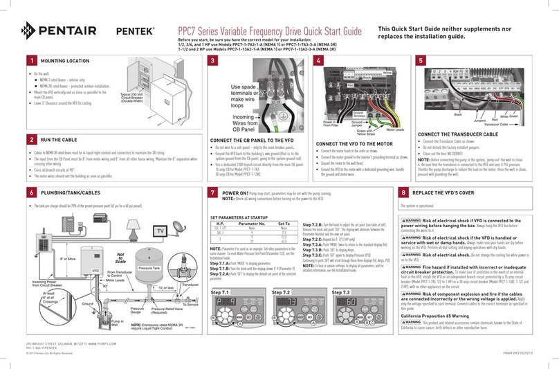
Conexiones de los cables
A. Desconectarlaalimentaciónalacajadeldisyuntor
antesderealizarlasconexiones.
B. ConectarPRIMEROelcabledelmotor,SEGUNDO,el
cabledeltransductor,yPORÚLTIMO,loscablesde
alimentación.InspeccionarelinteriordelMecanismo
deAccionamiento.Verificarquenotengacablessueltos
nisuciedadantesdecerrarlo.
C. Volveracolocarlacubiertayfijarlaconeltornillode
lacubiertaantesdeconectarelcabledealimentación
deentradaalacajadeldisyuntor.
AVISOCuandoseuseunmotorsobretierraclasificado
parausarconelPENTEKINTELLIDRIVE,lalongitud
máximadelcableconductordebeserde25pies(7.62m).
Consultarelmanualdelusuarioespecíficodelmotorylas
normasdeCódigoNacionaldeElectricidad(NEC)para
determinareltamañodelcable.
• Esnecesariodesconectarla
alimentaciónyesperar5minutos
antesdeabrirysacarlacubiertadel
MecanismodeAccionamiento.
• SedebemontarelMecanismode
Accionamientoenunpernooposte
ANTESderealizarlasconexiones
eléctricas.
• NosedebetocarelMecanismode
Accionamientoconmanoshúmedaso
mojadas.
• Sedebedesconectarlaalimentacióny
sacarlacubiertaconmanossecas.
Peligro de incendio. Siseinstalacon
proteccióndeundisyuntorincorrecto.El
MecanismodeAccionamientosedebe
instalarenunramalindependiente,sin
ningúnotroaparatoelectrodoméstico
conectadoalcircuitoydebeestar
protegidoporundisyuntor,talcomose
especificaenelManualdelPropietario.
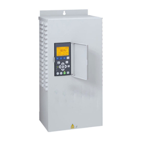
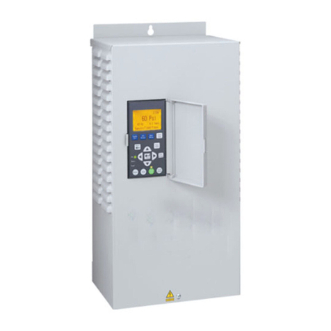
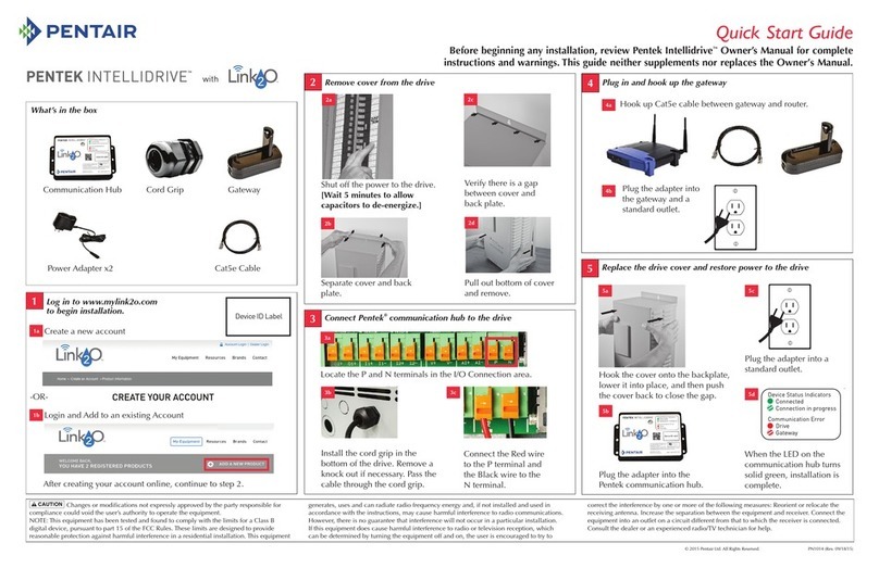
Procedimiento de instalación del Mecanismo de Accionamiento
• Comenzarelprocedimientoconlaremocióndeltornilloenlaparteinferiordelacubierta
delantera.
• Jalardelapartesuperiordelacubiertahaciausted(Fig.1a),alejándoladelaplaca
posteriorparacrearunespacio(Fig.1b).
• Jalardelaparteinferiordelacubiertahaciausted(Fig.1c);levantarysacarlacubierta.
• MontarelMecanismodeAccionamientoenposiciónverticalenunperno,posteosobre
unasuperficieplana.
• FijarelMecanismodeAccionamientoenformapermanenteusandoelorificiosuperior
ranurado,yyaseanlostresorificiosinferiores(paraelmontajesobreunasuperficieplana)
oelorificiocentralinferior(paraelmontajesobreunposteoperno).
• Dejarunespaciolibrede3pulgadas(7.62cm)alrededordelMecanismode
Accionamientoparaproporcionarunenfriamientoadecuado.
1
Disyuntor
típicode
230voltios
(doble
ancho)
Filtro EMI/RFI
Peligro de choque eléctrico.Puede
provocarchoques,quemaduraso
muerte.Sedebeestaratentoariesgos
talescomo:
• Loscomponentesinternosdel
MecanismodeAccionamiento
retienenunatensiónaltahasta
5minutosdespuésdehaber
desconectadolaalimentaciónde
entrada.
• ElFiltroEMI/RFItieneunatensión
altacuandolabombaestáen
marcha.
Pulse “Enter” (Ingresar)
Pulse “Enter” (Ingresar)
Pulse “Enter” (Ingresar)
Pulse “Enter” (Ingresar)
6566 0512
Aplique 230 V
al Mecanismo
Configure la hora
Configure la fecha
Configuración completa
Monofásico (1)
Tipo de conexión
[bifilar (2) o trifilar (3)]
Trifásico (3)
Tipo de Motor
Sumerg. o sobre sup.
Ingrese amperaje de
factor de servicio
Ingrese fase del motor
[monofásico (1) o trifásico (3)]
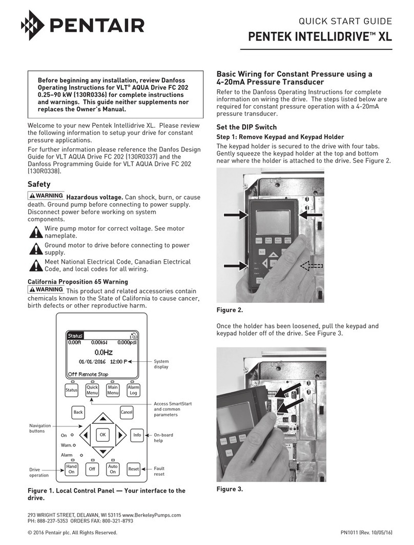
Arranque Inicial: Programar el Mecanismo de
Accionamiento
Aplicarunapotenciade230V
alPENTEKINTELLIDRIVE.
“SetupGuide”(Guíade
Configuración)aparecerá
enlapantalla.Oprimirlas
teclasenelorden
indicadoaquí:
3
Setup Guide 12:10p
Service Factor Amps
Stopped
Arranque Inicial: Lista de Verificación
• Verificarqueelsistematengaunaválvuladedesahogoyuntanqueapresióndel
tamañoadecuado.
• Verificarquelaprecargadeltanqueapresiónseaun70porcientodelapresiónde
referenciadelunidad(42PSI(librasporpulgadacuadrada)paraelpuntodereferencia
predeterminadode60PSI).
• Verificarqueladescargadelabombaestéconectadaalsistema.
• Verificarqueloscablesatierradeentrada,desalidaydelblindajedeltransductor
esténdebidamenteconectados.
5
Pulse “Enter” (Ingresar)
Pulse “Enter” (Ingresar)
Pulse “Enter” (Ingresar)
Pulse “Enter” (Ingresar)
Pulse “Enter” (Ingresar)
6566 0512
Aplique 230 V
al Mecanismo
Configure la hora
Configure la fecha
Configuración completa
Monofásico (1)
Tipo de conexión
[bifilar (2) o trifilar (3)]
Trifásico (3)
Tipo de Motor
Sumerg. o sobre sup.
Ingrese amperaje de
factor de servicio
Ingrese fase del motor
[monofásico (1) o trifásico (3)]
(Continúaenlacolumnasiguiente)
Gu
í
a B
á
sica de Inicio
Consultar el Manual del Propietario para obtener información sobre la instalación, el funcionamiento y la seguridad.
Esta guía no suplementa ni sustituye el Manual del Propietario.
AVISO Losamperiosindicadosenla
placadefábricapuedenserdiferentesde
estosvalores.ParalosmotoresPENTEK,
uselosvaloresindicadosaquí.
Enusosdereadaptaciónsumergiblecon
motorestrifilares,monofásicosdeotros
fabricantes,sedebenusarlosvaloresde
arranqueymarchadelcapacitor(CapStart/
CapRun)suministradosporelfabricante
delmotor.Paramotorestrifásicos,sedebe
usarelamperajedelfactordeservicio
indicadosporelfabricantedelmotor.
Paramotoressobretierra,sedebeusar
elvalordeamperiosmásaltoindicado
(puedeestarindicadocomo“amperios
decargamáx”ocomo“amperiosaplena
carga”).
AVISOConsultarelManualdelPropietario
paraobtenermásilustracionese
informacióndetallada.
Para obtener asistencia,
llamar al Departamento de
Atención al Cliente de PENTEK
1-866-9PENTEK (973-6835)
2
AVISODespuésdehabercompletadotodaslasconexionesdeloscablesenelPaso2,
volverafijarlacubiertaenganchándolaenlapartesuperiordelaplacaposterior(es
importantedejarunespacio).Bajarycolocarlaparteinferiordelacubiertaenposición.
Empujarlacubiertauniformementecontralaplacaposterior(Fig.1d),eliminandoel
espacio.Volveracolocareltornilloenlaparteinferiordelacubiertadelantera.
1a
1b
1c
1d

