3
VERUS®850 Premium Efficient Aquaculture Duty Pump Installation and User’s Guide
VERUS®850 Premium Efficient Aquaculture Duty Pump Installation and User’s Guide
Mechanical Installation (Continued)
7. Placethepumpinitsnallocationandensure
that the mating anges of the suction and
dischargepipingareinlineandparalleltothe
angesonthepump.Resolveanyproblems
withmisalignmentbeforeboltingtheanges
tothepump.
8. Thepumpmaybesecuredtoboltsburiedin
theconcretebyusingtheholesontheoutside
ofthemotorsupports.
9. Ensure that the ange gasket is properly
positionedbetweenthesuctionangeofthe
pumpandtheangeofthesuctionpiping.
Useonlyhighqualityrubber,fulldiameter
angegasketswithholesfortheboltstopass
through.Itmaybenecessarytoholdthegasket
inplacewitheithersiliconeortwoorthree
dropsofacyanoacrylate(superglue)material.
Donotuseanyothergreaseorglueasthey
maycontainchemicalsthatcouldattackthe
plasticmaterial.Installtheangeboltshand
tightonthesuctionsideofthepump.
* INCLUDED WITH STRAINER POT
HEX NUT M20 x 25 (5/8-11)
P/N 356788 *
P/N 356789 *
P/N 356766 *
(5/8" ID X 1-5/16") MIN OD
FLAT WASHER
(6" ANSI CLASS 150) FLANGE
SUCTION CONNECTIONWITH
STRAINER POT
70 DURO NITRILE OR EPDM
3.2 mm (1/8") THICK GASKET
22.1 mm (5/8" ID X 1-5/16") MIN OD
FLAT WASHER
HEX HEAD CAP SCREW
M20 x 25, 80 mm (5/8-11 X 3-1/4") LG
Optional accessory flange kit
70 DURO NITRILE OR EPDM
3.2 mm (1/8") THICK GASKET
6" ANSI CLASS 150 FLANGE
SUCTION CONNECTIONWITHOUT
STRAINER POT
22.1 mm (5/8") ID X 44 mm (1-5/16") MIN OD
FLAT WASHER
HEX HEAD CAP SCREW
5/8-11 X 2-1/4" LG
Figure 1.
CAUTION — Some off the shelf, non-Pentair, 6” flange adapters will not work with pump without the strainer pot. Note
the tabs on the flange on the left, (Figure 3). These tabs will interfere with the strainer pot alignment
lip on the housing. This lip is used to locate the strainer pot on models that are so equipped. Please
contact Pentair for a replacement flange adapter kit (Pentair P/N 357212).
CAUTION — Use large diameter flat washers between the hex nut and the pump flanges to properly distribute the
clamping forces on the flange. Tighten the flanges to 20 ft.-lb. (27.1 newton/meters) unless otherwise
specified by the flange manufacturer. If it is not possible to use a torque wrench then care should be
taken not to over tighten the flange bolts. Failure to follow the above instructions can result in damage
to the pump flange.
10. Properlyinserttheangegasketonthedischargeportofthepump.Installtheangeboltshandtightonthe
dischargeangeconnection.
11. Inspectboththesuctionandangeconnectiontoensurealignmentremainsacceptable.Takeanycorrective
actionbeforetighteningtheangeboltstotherequiredtorque.
CAUTION — Suction and discharge piping must be supported by an appropriate system of supports or hangers.
Inadequately supported pipe can cause excessive loads to be transmitted to the pump resulting in a
structural failure of the pump that could result in flooding and property damage.
Flange kit part numbers (available separately)
• P/N 357259: FLANGE 2.5 INCH SCHEDULE-80 WITH GASKET AND S/S HARDWARE (QTY. 1)
• P/N 357260: FLANGE 5 INCH SCHEDULE-80 WITH GASKET AND S/S HARDWARE (QTY. 1)
• P/N 357261: FLANGE 3 INCH SCHEDULE-80 WITH GASKET AND S/S HARDWARE (QTY. 1)
• P/N 357262: FLANGE 4 INCH SCHEDULE-80 WITH GASKET AND S/S HARDWARE (QTY. 1)
• P/N 357263: FLANGE 6 INCH SCHEDULE-80 WITH GASKET AND S/S HARDWARE (QTY. 1)
• P/N 357212: FLANGE 6 INCH SCHEDULE-80 WITH GASKET AND S/S HARDWARE WITHOUT POT (QTY. 1)
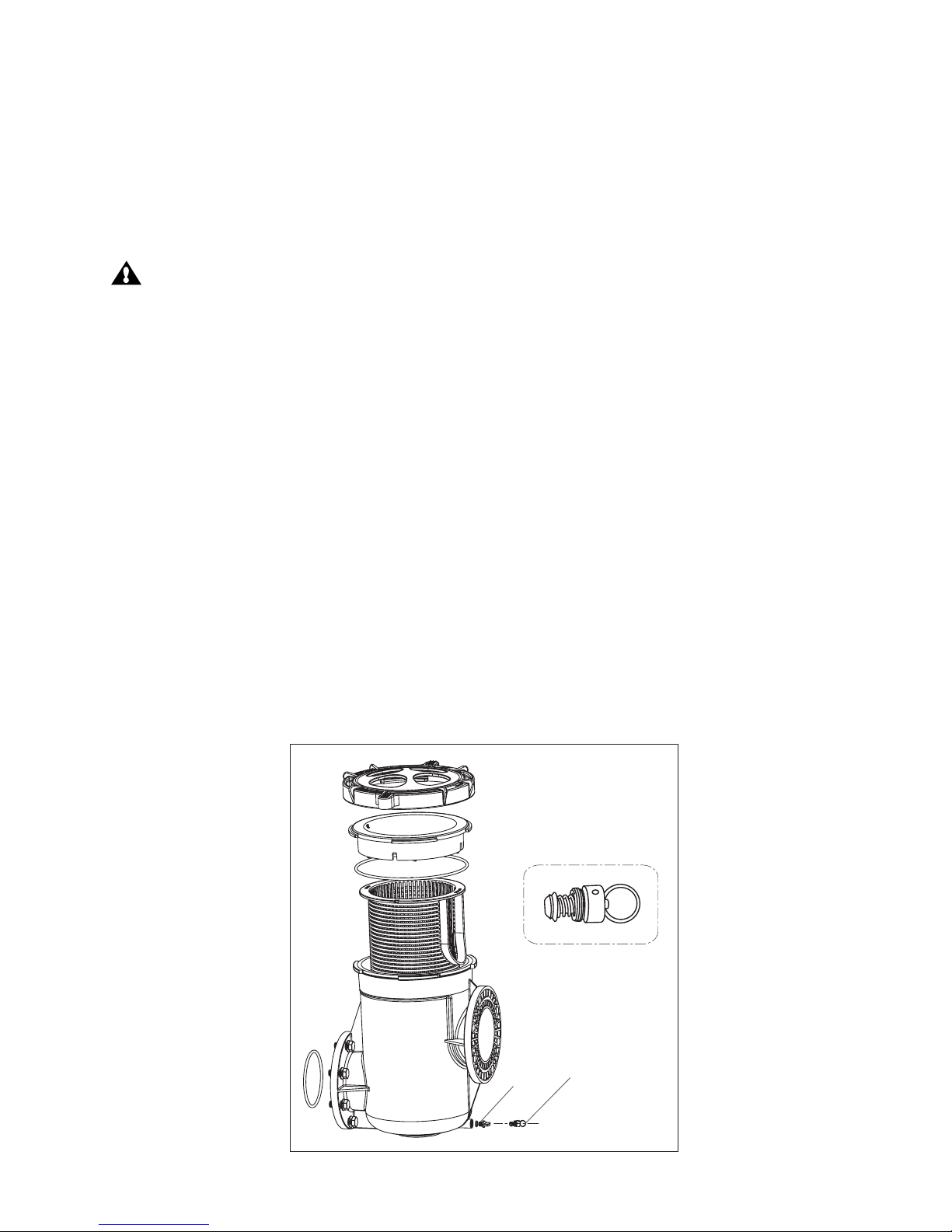
OPTIONAL STRAINER POT ASSEMBLY (P/N 347013)
SUCTION CONNECTION WITH
STRAINER POT ASSEMBLY AND
OPTIONAL FLANGE KIT
SUCTION CONNECTION WITHOUT
OPTIONAL STRAINER POT ASSEMBLY
Figure 2.
Figure 3.
TABS