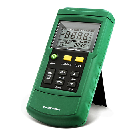
Perfect Prime TC0370 User manual

RTD THERMOMETER
TC0370
Instruction Manual

CONTENTS
P. 1
1. Introduction
2. Specifications
3. Symbol Definition and Button Location
4. Operation Instructions
4.1 Power-Up
4.2 Connecting the temperature probe
4.3 Selecting the Temperature Scale
4.4 Data-Hold Operation
4.5 Back light Operation
4.6 Relative Operation
4.7 MAX/MIN/AVG Operation
4.8 Auto Power O
4.9 Low Battery Condition
5. Temperature Measurement
6. Temperature Meter Calibration Setup
7. Maintenance
7.1 Replacing the Batteries
7.2 Cleaning
8. Temperature Probe
......................................................................... 2
.................................................................. 3 - 4
.............................. 5 - 6
......................................................................... 7
....................................... 7
........................................... 7
.......................................................... 7
........................................................... 7
.............................................................. 8
.................................................... 8
.................................................................. 9
....................................................... 9
.................................................. 10
............................. 11 - 15
..................................................... 16
......................................................................... 17
.............................................................. 18
1. INTRODUCTION
P. 2
This instrument is a digital thermometer for use with platinum-type
temperature sensor.
Temperature indication follows IEC751 temperature table for PT-type
sensor.

NUMERICAL DISPLAY:
4 digital liquid crystal display
MEASUREMENT RANGE:
-100°C ~ 300°C; -148°F ~ 572°F
RESOLUTION:
Platinum resistance temperature sensor for pt-100, pt-500, pt-1000
(selectable) 4 wires.
ALPHA=0.003850
MEASUREMENT CURRENT:
Approx 0.53mA
MAXIMUM VOLTAGE AT TEMPERATURE COUPLE INPUT:
60V DC, or 24Vrms AC
ENVIRONMENTAL:
• Operating Temperature and Humidity:
0°C ~50°C (32°F ~ 122°F) ; 0 ~ 80% RH
• Storage Temperature and Humidity:
-10°C to 60°C (14°F ~ 140°F); 0 ~ 80% RH
• Altitude up to 2000 meters.
ACCURACY: AT 18°C TO 28°C64.4°F TO 82.4°F
2. SPECIFICATIONS
P. 3
Range Accuracy
-100°C ~ 300°C
-148°F ~ 572°F
±(0.1% reading + 0.4°C)
±(0.1% reading + 0.8°F)

TEMPERATURE COEFFICIENT:
For ambient temperatures from 0°C ~ 18°C(32°F ~ 64.4°F ) and 28°C
~ 50°C(82.4°F ~122°F), for each °C/°F ambient below 18°C(64.4°F) or
above 28°C(82.4°C) add the following tolerance into the accuracy spec.
0.01% of reading + 0.03°C ( 0.01% of reading + 0.06°F )
Note:
The basic accuracy Specication does not include the error of
the probe please refer to the probe accuracy specication for
additional details.
SAMPLE RATE: 2 Times Per Second
WATER RESISTANCE: IP67
DIMENSION: 150 × 66 × 31mm
WEIGHT: 175g Approx.
ACCESSORY: PT-100 Probe(class A), Battery, Instruction Menu
OPTION: Connection Cable
POWER REQUIREMENT: Battery 1.5V X 3 Size AAA
BATTERY LIFE: Approx. 100hours With Alkaline Battery
2. SPECIFICATIONS
P. 4

3. SYMBOL DEFINITION AND
BUTTON LOCATION
P. 5
This indicates that the minus temperature is sensed
Celsius and Fahrenheit indication
Platinum Type Indication
This indicates that the display data is being hold
The Maximum value is now being displayed
The Minimum value is now being displayed
The Average value is now being displayed
The reading is now under Relative Mode
The Battery power potential indication
This indicates Auto Power O is enabled
REL
AVG
MAX
MIN
HOLD
PTxxx
°C °F
-

3. SYMBOL DEFINITION AND
BUTTON LOCATION
P. 6
1
2
3
4
5
6
7
8
Pt type temperature
sensor connector
LCD display
Power ON/OFF button
HOLD button
2
3
4
1MAX MIN Average control
button
Back light button
Relative readout button
°C , °F control button
6
7
8
5

4. OPERATION INSTRUCTIONS
P. 7
4.1 Power-Up
Press the key to turn the thermometer ON or OFF.
4.2 Connecting the temperature probe
For measurement, plug the temperature probe into
the input connectors.
4.3 Selecting the Temperature Scale
When the meter was rst powered on, the default scale setting is set
at Celsius (°C) scale. The user may change it to Fahrenheit (°F) by
pressing “ °C/°F ”button and vice versa to Celsius.
4.4 Data-Hold Operation
The user may hold the present reading and keep it on the display by
pressing the “HOLD”button. When the hold data is no longer
needed, one may release the data-hold operation by pressing
“HOLD” button again.
When the meter is under Data Hold operation, the“ REL”,
and “ °C/°F ” button are disabled.
4.5 Back light Operation:
Press the“Back Light” button to turn back light on and press it once
again to turn it o.
The meter will turn back light o if there is no push“Back Light”
button for 10 seconds.

4. OPERATION INSTRUCTIONS
P. 8
4.6 Relative Operation:
When one presses the“ REL” button, the meter will memorize the
present reading and the dierence between the new reading and the
memorized data will be shown on the display. Press the“ REL”
button again to exit the Relative operation.
4.7 MAX/MIN/AVG Operation:
When one presses the button the meter will enter the
MAX/MIN/AVG mode. Under this mode the maximum value,
minimum value and average value of latest 8 data is kept in the
memory simultaneously and updated with every new data.
When the MAX symbol is displayed, the Maximum is shown on the
display.
Press again, then the MIN symbol is on the display and also
the minimum reading.
Press again, the AVG symbol is on the display and also the
average reading.
Press again, MAX, MIN and AVG will blink together. This means
that all these data is updated in the memory and the reading is the
present temperature.
One may press to circulate the display mode among these
options.
When the meter is under operation, “ REL” and “°C/°F ” are
disabled.
To exit the MAX/MIN mode, one may press and hold for two
seconds.

Battery OK, measurements are possible.
Battery Low, battery needs to be replaced,
measurements are still possible.
Battery exhausted, the battery need to
replaced with new one(size AAA, 1.5V x 3).
4. OPERATION INSTRUCTIONS
P. 9
4.8 Auto Power Off:
By default, when the meter is powered on, it is under auto power o
mode. The meter will power itself o after 30 minutes if no key
operation.
One may press and hold“HOLD” button and then power on the
meter and there will be two successive beeps to indicate that auto
power o is disabled.
4.9 Low Battery Condition:
The temperature meter incorporates visual low battery indication as
follows:

5. TEMPERATURE MEASUREMENT
P.10
5.1 Correct Measurement Method:
The temperature sensor is located at the end of the metal sheath of
the sheath type TEMPERATURE PROBE.
To accurately test internal temperature insert the probe into the item
you want to measure to a distance at least 15 times the diameter of
the sheath.
5.2 Connector Configuration:

Note:
Turn the Power “OFF”before attempting following SETUP.
Setup mode is cancelled during below procedure if“POWER”
button is pressed.
P.11
6. TEMPERATURE METER
CALIBRATION SETUP
Below table diagram shows each button function when user enter into
calibration mode.

P.12
6.1 Pt type selection
6-1-1.
Press and hold“Power” + “Light” buttons for 2
seconds to enter setup mode.
6-1-2.
Press“Hold” button to enter PT selection mode.
6-1-3.
Press“Max” button to select between PT probe
type.
(Pt100, Pt500, Pt1000 is circulate)
6-1-4.
Press“°C/°F”button to conrm selection.
6. TEMPERATURE METER
CALIBRATION SETUP

P.13
6. TEMPERATURE METER
CALIBRATION SETUP
6.2 0 °C Calibration
6-2-1.
Press and hold“Power” + “Light” buttons for 2
seconds to enter setup mode.
6-2-2.
Press “REL” button to enter calibration mode.
Enter PT selection rst.
6-2-3.
Press “°C/°F”button to conrm PT selection.
6-2-4.
Press“REL” button to enter calibration mode.
Insert temperature probe into 0°C Deg.
Standard calibration unit before
calibration. Hold the probe until condition
is stabilized before starting calibration.

6. TEMPERATURE METER
CALIBRATION SETUP
P.14
6-2-5.
Press “REL”button to conrm present calibration
value.
6-2-6.
Press “°C/°F”button to conrm selection.
6.3 Recall Default factory setting value
6-3-1.
Press and hold“Power” + “Light” buttons for 2
seconds to enter setup mode.
6-3-2.
Press“REL” button to enter calibration
mode. Enter PT selection rst.

P.15
6. TEMPERATURE METER
CALIBRATION SETUP
6-3-3.
Press “°C/°F”button to conrm PT selection.
6-3-4.
Press “Light”button to enter recall mode.
6-3-5.
Press “°C/°F”button to conrm revert back to
“Default factory setting value”.
6-3-6.
Press “°C/°F”button to conrm selection.

P.16
7. MAINTENANCE
7.1 Replacing the Batteries
7.1.1 Remove back cover screw to remove cover. Verify polarity and
install new LR03(AAA size) alkaline batteries.
7.1.2 Fit cover properly and tighten screw.
The unit’s back cover are tted with rubber rings. After replacing
the battery, check that the rubber rings are properly seated
before reinstalling the back cover. Improper seating of the
rubber rings will compromise the unit’s water-resistant structure,
and possibly result in damage to the equipment.

7. MAINTENANCE
P.17
7.2 Cleaning
In order to ensure the accuracy of the thermometer for a longer
period of time you should calibrate it once a year.
Clean the device and the window of the display with a clean, lint-free,
antistatic and dry cleaning cloth.
Do no use cleaning agents that contain carbon or benzenes,
alcohol or anything similar to clean the product since these
substances damage the surface of the measuring instrument.
Moreover, these fumes are hazardous to health and explosive.
Do not use tools with sharp edges, screwdrivers, metal brushes
or anything similar to clean the device.

Sensor Type
Accuracy
Measurement Range
Temperature Sensor
Dimensions
Temperature Sensor
Length
Cable Length
Water-resistant
Platinum resistance thermometer sensor
Pt 100(4 wires)
IEC751, class A
±0.15°C±0.002t
(t: measurement temperature)
-100 to 400°C (-148 to 752°F)
Approx. ø3.2mm(ø0.125”)
Approx. 120 mm(4.72”)
Approx. 1100 mm(43.3”)
EN60529:1991 IP67
P.18
8. TEMPERATURE PROBE
8.1 Piercing type temperature probe
8.2 Piercing type temperature probe Specification

CUSTOMER SERVICE INQUIRIES
Your emails are important to us so we strive to reply all
inquiries and emails within 24 hours. In exceptional cases,
we may require more time to respond.
Thank you for your understanding.
For more information about our products and services,
please send us an email:
For B2B or project-based application, please send an email:
FOR MORE INFORMATION ABOUT PERFECTPRIME PLEASE VISIT
OUR ABOUT US PAGE AND FEEL FREE TO BROWSE.
Scan QR Code for the Product
Manual page (Multi-Language
available for certain products)
Scan QR Code for the Youtube
channel for video manual
Scan QR Code to register the
product for 1 year warranty
Table of contents
Other Perfect Prime Thermometer manuals

Perfect Prime
Perfect Prime TC2100 User manual

Perfect Prime
Perfect Prime TM0819 User manual

Perfect Prime
Perfect Prime TM118 User manual

Perfect Prime
Perfect Prime TM0300 User manual

Perfect Prime
Perfect Prime TC0355 User manual

Perfect Prime
Perfect Prime TC2100 User manual

Perfect Prime
Perfect Prime TC41 User manual

Perfect Prime
Perfect Prime TM0300 User manual