CONTENTS
P. 1
1. Safety Information
2. Product Overview
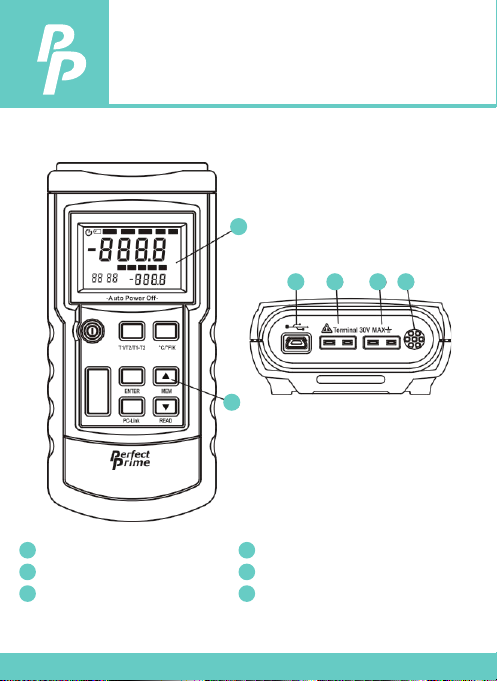
3. Meter Description
3.1 Component
3.2 Display
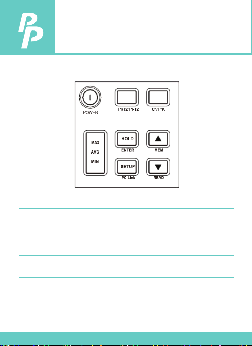
3.3 Keys Description
4. Setting Meter
4.1 SETUP Option
4.2 SETUP Option Setting
5. Using The Meter
5.1 Connecting thermocouple
5.2 Displaying Temperature
5.3 Data Hold
5.4 Viewing MAX, MIN and AVG
Readings
5.5 Use Oset value To Adjust
Temperature probe error
5.6 User Self-Calibration
6. Data Storage
6.1 Data Storage
6.2 Data Reading
6.3 Clearing Stored Data
7. Meter Maintenance
8.1 Replace Battery
8.2 Clean
8. Technique Data
................................................................... 2 - 3
.................................................................... 4
................................................................ 5 - 8
.............................................................................................. 5
........................................................................................................ 6
............................................................................... 7 - 8
..................................................................... 9 - 12
.......................................................................................... 9
................................................................... 9 - 12
............................................................... 13 - 15
............................................................... 13
.................................................................... 13
................................................................................................ 13
............................................................. 13
................................................................ 14
.................................................................. 14 - 15
.................................................................... 16 - 17
.......................................................................................... 16
......................................................................................... 16
.......................................................................... 17
................................................................ 18
..................................................................................... 18
........................................................................................................ 18
................................................................ 19 - 20