manuals.online logo
Brands
  1. Home
  2. •
  3. Brands
  4. •
  5. Perrycraft
  6. •
  7. Automobile Accessories
  8. •
  9. Perrycraft SportQuest User manual

Perrycraft SportQuest User manual

ROOF RACK INSTALLATION INSTRUCTIONS (ALL RAIL LENGTHS)
1549 US Highway 21 South
Sparta, NC 28675
336-372-2545
[email protected]
www.perrycraft.com
ROOF RACK INSTALLATION INSTRUCTIONS
(ALL RAIL LENGTHS)
Before contacting/returning this product to your place of purchase,
contact Perrycraft, Inc.® at 336-372-2545 for any technical
questions, problems, missing parts, etc., upon opening your
product and verifying all parts are present.
RETURNS: Any product to be returned must be returned to the place of
purchase, and is subject to the seller’s returns policy. DO NOT return to
Perrycraft unless instructed to do so in writing.
IMPORTANT NOTES:
RACK LOCATION: Perrycraft’s products are manufactured to be installed
into the skin of the roof panel of vehicles. They are not designed to line up
or be installed at the factory fitment points available on some vehicles.
INSTALLATION HARDWARE: The included hardware pack contains screws
for securing this rack to a sheet metal roof or metal surface. To install this
rack on fiberglass or composite camper tops, tonneau covers, or Jeep
©
tops,
please contact your seller to purchase hardware pack HWDSTC-UV, or call
336-372-2545 to purchase directly from Perrycraft, Inc.®
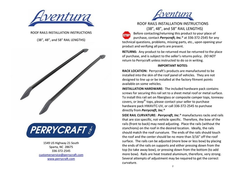
SIDE RAIL CURVATURE: Perrycraft, Inc.® manufactures racks and rails that
are size specific, not vehicle specific. Therefore, the bow of the rails (front
to back) may need adjusting. Place the rails (without the stanchions) on the
roof in the desired location. Ideally, the rails should match the roof
curvature. The ends of the rails should touch the roof and the center should
be no more than 3/16” off the roof surface. The rails can be adjusted (more
bow or less bow) by placing the ends of the rails on supports and either
pressing down from the top (to take away bow), or pressing down from the
bottom (to add more bow). Rails are heat treated aluminum, therefore,
very strong. Several attempts of adjustment may be required to get the
correct curvature.
ITEMS NEEDED (NOT INCLUDED)
 Measuring Tape
 Masking Tape
 Marker
 Drill
 1/8” and 3/16” Drill Bits
 Phillips Screwdriver
2
 Hammer
 Adjustable or 7/16” Wrench
 Rag and Cleaner for roof
Retain these instructions. They are useful if contacting Perrycraft for
information, parts, or service.
CONTENTS:
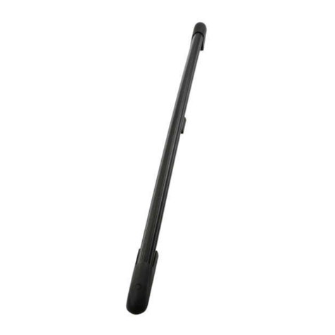
 2 – Side Rails (Rails will be 2” shorter than last two numbers of
part number (ex. SQ5550-B, rails are 48”)
 2 – Cross Bars (Either 55”, 62”, or 70”)
 4 – Stanchion Assemblies
 1 – Hardware pack
o 4 – 1/4” Stainless Steel Flat Washer
o 1 – 3/16” Allen Wrench
o 8 – #10 x 1/2” Truss Phillips Screw Black – Waxed (8
screws for 40” rails, 10 for 50”, 12 for 60”, 14 for 70”,
and 16 for 80”)
o 4 – #10 x 3/4” Pan Phillips Screw – Waxed
o 4 – 1/4” x 20 Stainless Steel Nylon Lock Nut
o 4 – 1/4” x 20 x 7/8” Stainless Steel Socket Head Cap
Screw
o 4 – 3/16” x .469 Aluminum Drive Rivet
o 4 – SportQuest Rail Bracket Knob
o 4 – SportQuest Rail Bracket
o 4 – SportQuest/SporTrek Rail End Cap
o 4 – SportQuest/SporTrek Rail Tie Down Loop
o 4 – SportQuest Stanchion Plug
o 4 – SportQuest Cross Bar End Cap
ASSEMBLY AND INSTALLATION:
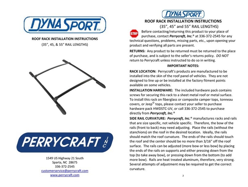
SportQuest® racks can be configured in two specific ways, Pass-
Through Fit or Stanchion Fit. Pass-Through Fit is using the cross bars
in the purchased length and letting them pass through the
stanchions. However, they can be cut down to any desirable length.
Stanchion Fit is cutting the cross bars to fit exactly into the stanchions
3
and installing the stanchion plugs to get a more factory style look.
The included hardware and plugs will either be utilized for the
Stanchion Fit configuration, or will be discarded if choosing Pass-
Through. The cross bar end caps will be discarded if choosing the
Stanchion Fit.
Assembly and installation will include placing the rails and end caps
parallel on the roof and marking the hole locations, removing the rails
and drilling holes at the marked locations, cleaning the roof and
installing the rails and end caps, then assembling and installing the
cross bar assemblies.
PASS-THROUGH CONFIGURATION:
1. Slide 2 Tie-Down Loops onto the middle of each Rail.
2. Place rails onto roof in desired location (approximately 2-3 inches
forward of the back hatch joint) and running parallel with each other.
 For a smooth roof, the rails should be placed out as close as
possible to the weld joint (or close to the plastic strip running
front to back), while remaining on the flat part of the roof and
parallel with each other.
 For vehicles with ribbed roofs, the rails should be placed on a
plateau or in a valley near the outer edges that is wide enough
for the rails, while remaining on a flat part of the roof and
parallel with each other.
3. Tape rails to roof, making sure to avoid hole locations. Also, place
end caps on the ends of each rail.
4. Mark hole locations and remove rails and end caps.
5. Drill pilot holes where marked using 1/8” drill bit going no deeper
than 1/2”, being careful not to penetrate interior headliner. Clean
roof, removing all drill chips.
6. Place rails back onto roof, lining up with drilled holes. Using hand
screwdriver, secure rails to roof using supplied #10 x 1/2” truss head
waxed screws. Do not overtighten. Snug is enough.
7. Using hand screwdriver, secure end caps to roof using #10 x 3/4”
pan head waxed screws. Do not overtighten. Snug is enough.
4
8. Install two stanchions on each rail by hooking the stanchion
bracket under the rail lip, sliding the connecting arm of the stanchion
assembly on top of the stanchion bracket, and inserting the bracket
knob into the stanchion bracket. Place the assemblies (one forward
and one back) directly across from the other and tighten the knob.
9. Insert cross bars into stanchions and center, so that the same
amount of cross bar is sticking out of each stanchion. Using a short
pencil or marker, mark the hole closest to the center of the vehicle on
the underside of each stanchion. This is where a hole will be drilled
and the rivet will be driven in order to connect the cross bars to the
stanchions.
10. Remove cross bars, turn them over, and place on a non-marring
surface.
11. Drill 3/16” hole at marked locations, being careful to only drill
through half of the cross bar (not all the way through both walls).
12. Insert drive rivets into holes and hammer the pins until flush with
the rivet head.
13. Install cross bar end caps.
14. Reinstall cross bar assemblies back onto rails. If installed
correctly, cross bar assemblies should be able to move to various
positions along rails. Tighten bracket knobs when satisfied with
location of cross bars.
STANCHION FIT CONFIGURATION:
1. Slide 2 Tie-Down Loops onto the middle of each Rail.
2. Place rails onto roof in desired location (approximately 2-3 inches
forward of the back hatch joint) and running parallel with each other.
 For a smooth roof, the rails should be placed out as close as
possible to the weld joint (or close to the plastic strip running
front to back), while remaining on the flat part of the roof and
parallel with each other.
3. Tape rails to roof, making sure to avoid covering hole locations.
Also, place end caps on the ends of each rail.
5
4. Mark hole locations and remove rails and end caps.
5. Drill pilot holes where marked using 1/8” drill bit going no deeper
than 1/2”, being careful not to penetrate interior headliner. Clean
roof, removing all drill chips.
6. Place rails back onto roof, lining up with drilled holes. Using hand
screwdriver, secure rails to roof using #10 x 1/2” truss head waxed
screws. Do not overtighten. Snug is enough.
7. Using hand screwdriver, secure end caps to roof using #10 x 3/4”
pan head waxed screws. Do not overtighten. Snug is enough.
8. Measure and make note of outside to outside dimension of rails.
This measurement should be the same along the entire length of the
rails.
9. Square cut cross bars 6 -1/2” less than noted measurement. If
measurement is 44”, cross bars will be cut to 37-1/2” inches. File or
sand ends of cross bars to remove any burrs.
10. Install stanchion plugs into all four stanchions using 1/4”-20 x
7/8” cap screws, 1/4” flat washers, and nylon lock nuts.
11. Insert cut cross bars into stanchions so they butt against
stanchion plugs. Turn cross bars upside down and drill 3/16” hole
through remaining hole on stanchion, being careful to only drill
through half of the cross bar (not all the way through both walls).
12. Insert drive rivets into holes and hammer the pins until flush with
the rivet head.
13. Reinstall cross bar assemblies back onto rails. If installed
correctly, cross bar assemblies should be able to move to various
positions along rails. Tighten bracket knobs when satisfied with
location of cross bars.
6
NOTES AND WARNINGS:
 For vehicles with ribbed roofs, the rails should be placed on a
 plateau or in a valley near the outer edges that is wide enough
for the rails, while remaining on a flat part of the roof and
parallel with each other.
 All fasteners, knobs, and securing methods should be checked
frequently and tightened as necessary.
 It is recommended that the cross bars and any accessories be
removed when not transporting items and before entering a
car wash.
 Do not use rack if a part is cracked or broken. Contact
Perrycraft, Inc.® by phone at 336-372-2545 or e-mail to
techsupp[email protected] for assistance with purchasing a
new component.
 External roof racks do not increase the GVWR of the vehicle.
Total occupant and cargo load should not exceed the
manufacturer’s rated vehicle capacity.
 Maximum load for this rack is 180 pounds, evenly distributed
on the cross bar assemblies Torque applied to any straps,
cords, etc. holding down gear or equipment also increases the
“load weight” to the cross bars and roof.
 Large or flat items such as plywood, ladders, lumber, hang
gliders, canoes, kayaks, etc., can trap air and create wind lift.
Secure the ends of long objects directly to the front and back
bumpers or tie-down positions.
 Bulky or tall loads can create tremendous horizontal wind
resistance from headwinds and crosswinds. Extreme caution
should be used when transporting such loads.
7
Perrycraft, Inc.® Warranty Agreement
Three Year Limited Warranty
Perrycraft, Inc.® warrants this product against defective materials and
workmanship to the original owner for a period of three (3) years from
purchase/install date. This warranty is not valid if product is transferred to
another person. Perrycraft, Inc.® provides no warranty and accepts no
liability for normal wear and tear, incorrect installation, damage to vehicles,
property, and/or equipment, nor damage arising from improper use. The
sole remedy under this warranty agreement is replacement of component
parts during the warranty period. You may be required to send in the
component in question (at your expense) to have the part evaluated for a
warranty claim.
If you have a warranty issue, and for faster service, please email a digital
photo of the product/component in question, a brief description of the
situation, and a copy of your purchase receipt to
[email protected]. Our staff will contact you as soon as possible
to resolve the issue.
Registering Your Perrycraft Product
Thank you for your purchase of our product. Our goal is to manufacture
quality products that meet or exceed your expectations. We want to make
sure the product you have is registered with us in case there are any issues
that may arise. Please register your product by sending an email to
[email protected] with your name, product purchased,
purchase date, install date (if different than purchase date), phone number,
and a scanned copy of your receipt. We promise not to send spam emails,
but may contact you periodically with updated product information,
questions about your usage for research purposes, or safety information.
Perrycraft, Inc.® does not assume responsibility for style or size of rack
installed, improper rack installation, exceeding rack load limit, load securing
methods, vehicle roof strength, wind lift or any other factors beyond its
control. Wind noise is a definite when carrying items on top of a vehicle. It
is also possible with nothing on the bars. Sometimes wind noise can be
alleviated by moving the front cross bar toward the rear of the vehicle. If
wind noise persists, remove cross bars when not transporting items, or a
wind fairing may need to be purchased and installed.
INSQ-RK-SM 8 170226
Other Perrycraft Automobile Accessories manuals

Perrycraft RF 20 User manual

Perrycraft

Perrycraft RF 20 User manual

Perrycraft DynaSport Roof Rack User manual

Perrycraft

Perrycraft DynaSport Roof Rack User manual

Perrycraft Sportrek User manual

Perrycraft

Perrycraft Sportrek User manual

Perrycraft MontBlanc SCOTT User manual

Perrycraft

Perrycraft MontBlanc SCOTT User manual

Perrycraft SportQuest Series User manual

Perrycraft

Perrycraft SportQuest Series User manual

Perrycraft DynaSport  DSXX85-B User manual

Perrycraft

Perrycraft DynaSport DSXX85-B User manual

Perrycraft Aventura User manual

Perrycraft

Perrycraft Aventura User manual

Perrycraft Easy Go 01 User manual

Perrycraft

Perrycraft Easy Go 01 User manual

Perrycraft DynaSport Series User manual

Perrycraft

Perrycraft DynaSport Series User manual

Perrycraft MontBlanc BARRACUDA User manual

Perrycraft

Perrycraft MontBlanc BARRACUDA User manual

Popular Automobile Accessories manuals by other brands

Whispbar K1218 instructions

Whispbar

Whispbar K1218 instructions

Velleman CARS5000 manual

Velleman

Velleman CARS5000 manual

Thule 176 parts list

Thule

Thule 176 parts list

Vivanco UNIVERSAL CHARGER 3IN 1 POWER SET operating instructions

Vivanco

Vivanco UNIVERSAL CHARGER 3IN 1 POWER SET operating instructions

MasterTop 15433301 installation instructions

MasterTop

MasterTop 15433301 installation instructions

cam SHP Series operating manual

cam

cam SHP Series operating manual

Westin 28-0160 instructions

Westin

Westin 28-0160 instructions

Westfalia 96 26 70 manual

Westfalia

Westfalia 96 26 70 manual

BrandMotion SUTV-1040 installation instructions

BrandMotion

BrandMotion SUTV-1040 installation instructions

rough country 11826 manual

rough country

rough country 11826 manual

Kiyo D ULTIMATE User and installation manual

Kiyo

Kiyo D ULTIMATE User and installation manual

Kenwood CMOS-130 instruction manual

Kenwood

Kenwood CMOS-130 instruction manual

Aries P35-2004 installation manual

Aries

Aries P35-2004 installation manual

Steelcraft DS5 manual

Steelcraft

Steelcraft DS5 manual

FormFit HDW 5M 05 quick start guide

FormFit

FormFit HDW 5M 05 quick start guide

Air Weigh LoadMaxx Plus installation guide

Air Weigh

Air Weigh LoadMaxx Plus installation guide

NavLinkz CI-RL1-MMI3G manual

NavLinkz

NavLinkz CI-RL1-MMI3G manual

Rhino-Rack RLCP17 manual

Rhino-Rack

Rhino-Rack RLCP17 manual

manuals.online logo
manuals.online logoBrands
  • About & Mission
  • Contact us
  • Privacy Policy
  • Terms and Conditions

Copyright 2025 Manuals.Online. All Rights Reserved.