THE PHD WARRANTY COVERS THE CYLINDER, ISO VALVE,
MANIFOLD AND ALL OTHER COMPONENTS ON THE CYLINDER
WITH THE EXCEPTION OF THE -X26 CHECK VALVE. THE CHECK
VALVE IS PROVIDED AS A SERVICE TO THE CUSTOMER, BUT
DOES NOT CARRY THE PHD WARRANTY.
®SERIES BCS2-6 STRETCHING CYLINDER
REBUILD PROCEDURES
These procedures include instruction for units with cushions.
P.O. Box 9070, Fort Wayne, IN 46899
1-800-624-8511
For additional technical assistance, call:
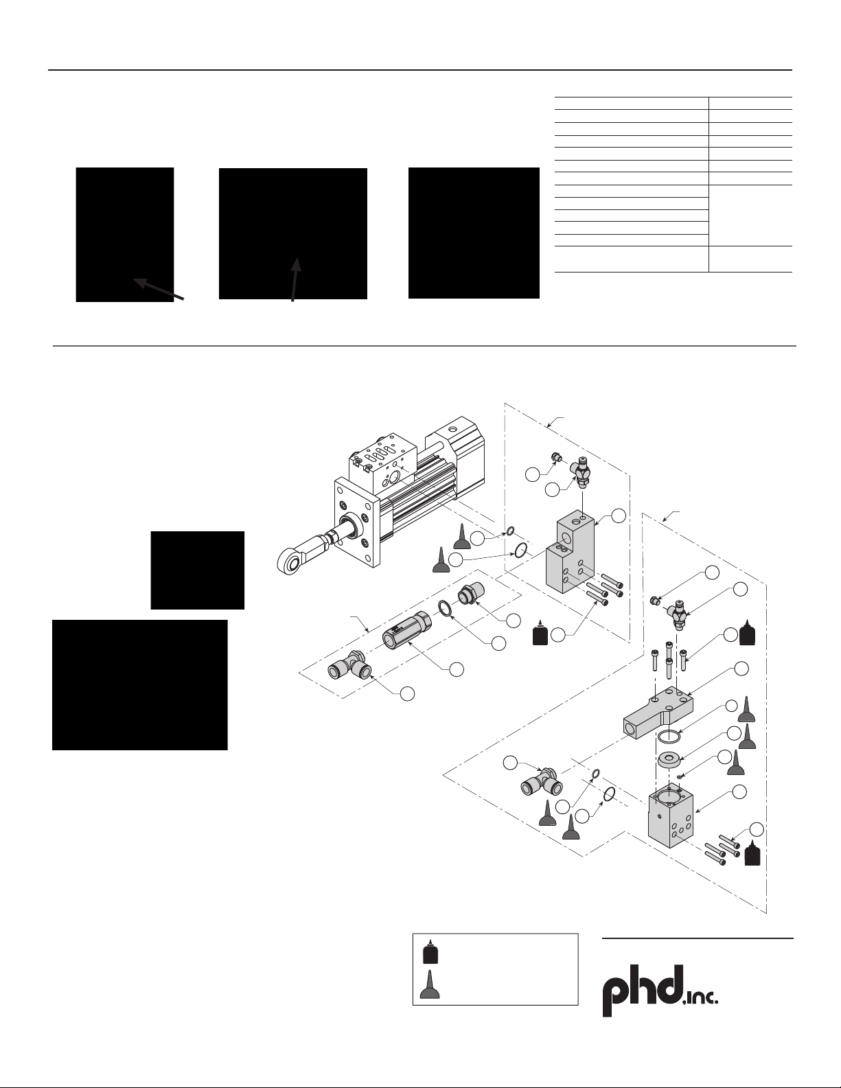
FIGURE 1
SHCS
MANIFOLD BLOCK
ASSEMBLY
MUFFLER
MUFFLER
STEEL TUBING
O-RING SEAL
MANIFOLD BLOCK
MANIFOLD TO
HEAD O-RING
SEAL
CAP ASSEMBLY
SHOULDER BOLT
W/ FEMALE THREAD
CAP
RETAINING RING
CUSHION NEEDLE
ASSEMBLY
MULTI-FUNCTION
IMPACT SEAL
CUSHION
O-RING SEAL
PISTON
SEAL
STEEL TUBING
O-RING SEAL
WEAR RING
PISTON SEAL
PISTON
PISTON & ROD
ASSEMBLY
STEEL TUBE
ROD CYLINDER
TUBE BORE
MULTI-FUNCTION
IMPACT SEAL
HEAD
ASSEMBLY
HEAD ROD BEARING
ROD SEAL
SHOULDER BOLT
W/ FEMALE THREAD
FLANGE
RETAINING
RING
FLANGE TO MANIFOLD
CAP SCREWS
JAM NUT
ROD EYE
FLANGE TO HEAD
CAP SCREWS
REBUILD/REASSEMBLY
1) Be careful to prevent cutting or damaging seals
during reassembly.
2) Use FDA Regulation 21CFR 178.3570 lubricant for
lubrication of air cylinders during reassembly.
3) Use FIGURE 1 for reference.
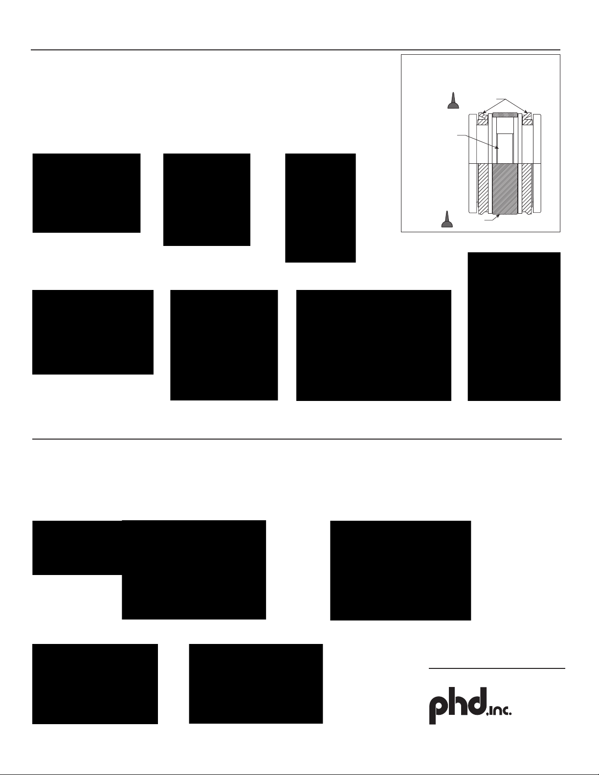
HEAD ASSEMBLY
A1) Press rod bearing into head, from end with snout, until flush as shown.
See FIGURE 2.
A2) Lubricate rod seal cavity and press in rod seal. Install retaining ring.
A3) Install multi-function impact seal in head.
!
Pre-lubricate rod seal cavity.
Pre-lubricate rod seal.
Insert rod seal into cavity.
Press rod bearing into head, from
end with snout, until flush as shown.
Lightly lubricate and install
multi-function impact
seal to head.
Caution: Over lubrication may cause cushion to malfunction.
TOOLS NEEDED:
Hex wrenches: M2.5, M4, M5, M6, and M8
Pliers
Small flat blade screwdriver
M24 open end or adjustable wrench
22 mm diameter pin or socket
(to press in rod bearing and rod seal)
Arbor press
20-250 in-lb torque wrench with
M2.5, M4, M5, M6 and M8 hex attachments
Press in rod seal.
PART NO.: 6441-503L
1
= LOCTITE 242 THREAD LOCKER
= LUBRICANT PER FDA
REGULATION 21CFR 178.3570
A1 A2
After installing retaining ring, apply a small amount of
lubrication to inside of rod seal.
A3
DISASSEMBLY OF THE CYLINDER
1) WARNING: All air pressure in the unit must be
exhausted prior to disassembly of nozzle cylinder.
2) Remove valve from manifold (valve not shown).
3) Remove mufflers from manifold if necessary.
4) Remove check valve, fitting adaptor, and male run tee
from manifold/inlet adaptor. If -X25, -X26 or -X27
(inlet adaptor) is present, remove from manifold.
5) Remove flange, rod eye, and jam nut.
6) Remove cap, carefully slide cap away from tube as not
to bend steel tube.
7) Remove steel tube.
8) Remove manifold.
9) Remove head.
10) Slide piston rod assembly from cylinder tube.
11) Remove all seals, noting orientation (especially note
orientation of rod seal). Exercise caution to prevent
scratching of the sealing surfaces. See FIGURE 2.
12) Remove cushion needle assembly (these items are
sold in separate kits from the cylinder repair kit).
13) Clean and inspect all components. Excessively worn or
damaged components should be replaced.
14) Clean flange bearing bore shoulder with acetone to
remove adhesive.
FIGURE 2
ROD BEARING
RETAINING RING
ROD SEAL,
NOTE ORIENTATION
FLANGE HEAD
FLANGE BEARING
BORE SHOULDER
FILL GROOVE
IN THIS
LOCATION