PFT G 5 c FU User manual

PFT G 5 c FU 230V Operating Manual Issued: 09.2007
Knauf PFT GmbH & Co. KG
1
OPERATING MANUAL
(Item number of operating manual: 00 11 01 43)
(Item number of machine – parts list: 00 02 08 05)
Mixer Pump
PFT G 5 c FU 230V
WE KEEP THINGS MOVING

PFT G 5 c FU 230V Operating Manual Issued: 09.2007
Knauf PFT GmbH & Co. KG
2
Contents
Contents 2
Dear PFT customer 4
Proper use of the machine 5
Description of functions 5
Overview of G 5 c FU: Item number 00 02 08 05 6
Overview of control box G 5 c FU: Item number 00 07 04 97 7
Overview of air manifold: Item number 00 03 96 13 8
Overview of water manifold: Item number 00 04 91 76 – 1000 ltr. 9
Basic safety instructions 11
Basic safety instructions 12
Signs 14
Technical Specifications 16
Settings 17
Mortar pump D6-2L 18
Start-up 19
Measures at the end of work and when cleaning 24
Clearing hose blockages 26
Measures to be taken in the event of a power failure 26
Measures to be taken in the event of a water supply failure 27
Measures to be taken if there is a risk of frost 27
Transport 28
Maintenance 28
Accessories 29
Fault – Cause – Remedy 30
Spare parts diagram of material hopper and frame 32
Spare parts list for material hopper and frame 33
Spare parts diagram of mixing tube and geared motor 34
Spare parts list for mixing tube and geared motor 35
Spare parts diagram of mortar pump / mortar pressure gauge 36
Spare parts list for mortar pump / mortar pressure gauge 37
Spare parts diagram of control box: Item no. 00 07 04 97 38
Spare parts list for control box: Item number 00 07 04 97 39
Spare parts diagram of control box: Item number 00 07 04 97 40
Spare parts list for control box: Item number 00 07 04 97 41
Spare parts diagram of water manifold: Item number 00 04 91 76 42
Spare parts list for water manifold: Item number 00 04 91 76 43
Spare parts diagram of booster pump: Item number 00 05 24 76 44
Spare parts list for booster pump: Item number 00 05 24 76 45

PFT G 5 c FU 230V Operating Manual Issued: 09.2007
Knauf PFT GmbH & Co. KG
3
Spare parts diagram of air compressor DT 4.16: Item number 00 07 64 44 46
Spare parts list for air compressor DT 4.16: Item number 00 07 64 44 47
Spare parts diagram of air manifold: Item number 00 03 96 13 48
Spare parts list for air manifold: Item number 00 03 96 13 49
Circuit diagram 50
Circuit diagram 51
Parameter settings for the Yaskawa type 606 V7 frequency converter 52

PFT G 5 c FU 230V Operating Manual Issued: 09.2007
Knauf PFT GmbH & Co. KG
4
Dear PFT customer
Congratulations on your purchase. You have made a wise choice as you clearly value the quality
that comes with a brand name product from a reputable company.
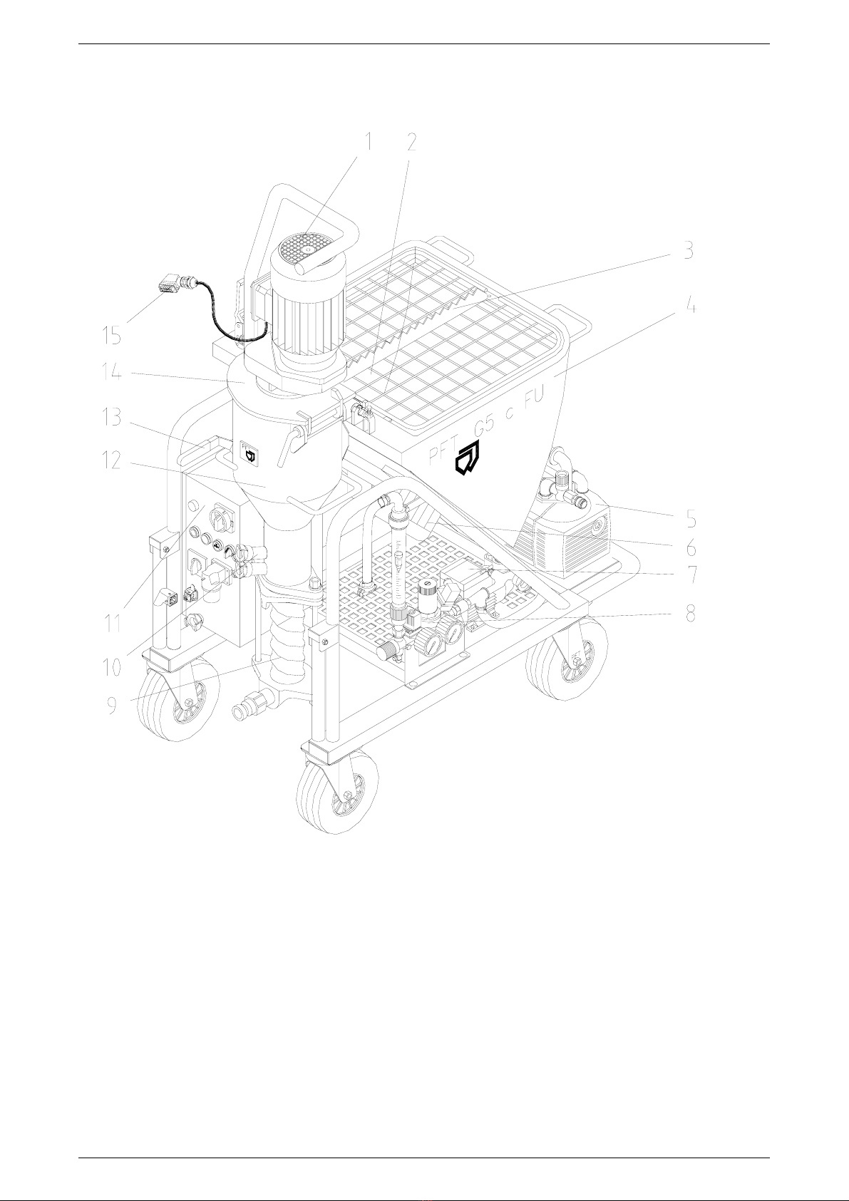
The PFT G 5 c FU mixer pump uses state-of-the-art technology. It was functionally designed to be
a reliable aid under rough construction site conditions.
This operating manual should always be stored and kept at hand at the site where the machine is
used. It contains information on the various functions of the machine. Study the operating manual
thoroughly before starting the machine, as we accept no liability for accidents or damage to the
machine caused by incorrect operation.
The PFT G 5 c FU mixer pump will prove to be a trustworthy aid providing it is operated correctly
and handled with care.
It is prohibited to forward this document, even excerpts, without our written authorisation. All
technical specifications, diagrams etc. are subject to copyright law. All rights, errors and
modifications are reserved.
Initial inspection after delivery:
An important task of all technicians delivering the PFT G 5 c FU is the inspection of the machine
settings at the end of the first work phase. The factory settings may change during the initial cycle.
If these changes are not corrected in time, immediately after run-in, problems may arise during
operation.
Following receipt of the PFT G 5 c FU mixer pump and training in regard to it, i.e. after about two
hours of operation, the technician must always carry out the following checks / make the following
settings:
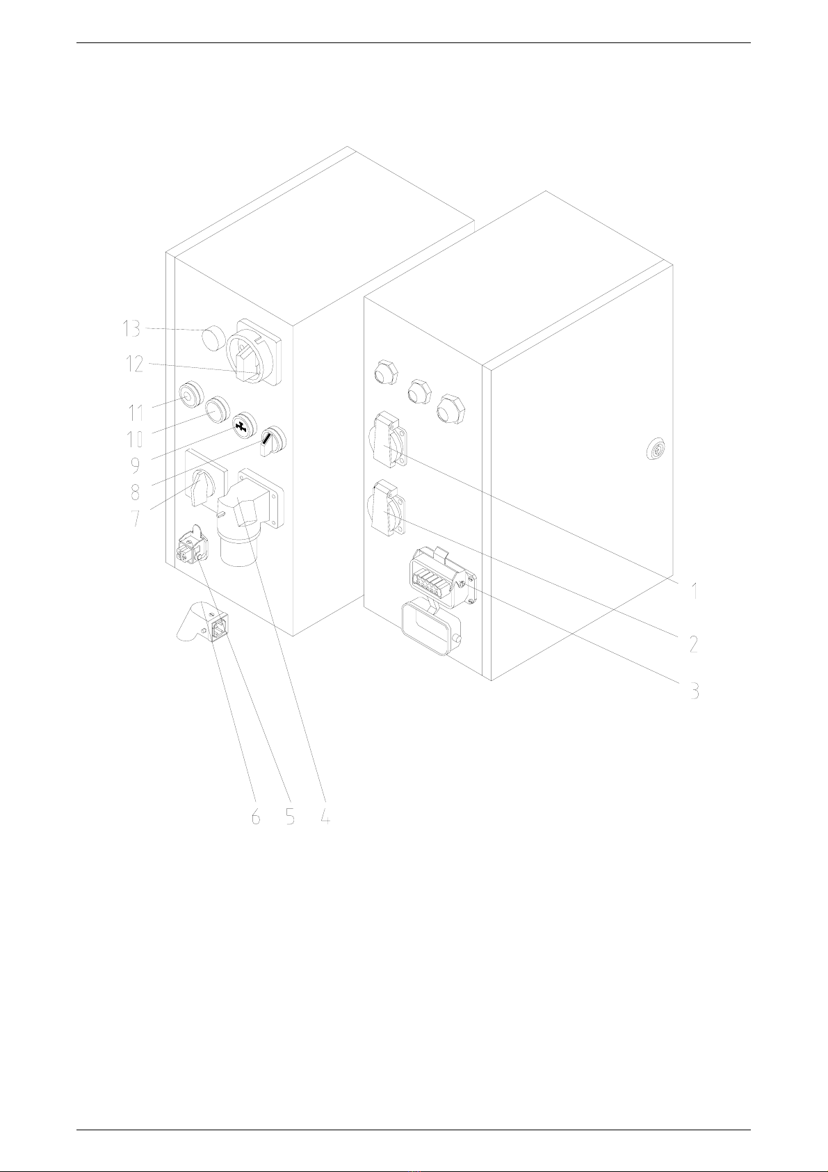
1) Water pressure switch
2) Pump pressure, backpressure
3) Air pressure switch
4) Pressure reducer
It is prohibited to forward this document, even excerpts, without our written authorisation. All technical
specifications, diagrams etc. are subject to copyright law. All rights, errors and modifications are reserved.
© by Knauf PFT GmbH & Co. KG

PFT G 5 c FU 230V Operating Manual Issued: 09.2007
Knauf PFT GmbH & Co. KG
5
Proper use of the machine
The PFT G 5 c FU is a continuously operating mixing pump for pre-mixed machinable mortar with
a particle size of up to 2 mm.
Please observe the processing guidelines of the material manufacturer!
The machine consists of portable individual components of handy dimensions that allow fast,
convenient transport.
The following points should be observed during operation:
1) Connection for worksite distribution board – control box
2) Connection for control box – pump motor
3) Connection for control box – compressor
4) Connection for compressor – air manifold
5) Connection for water supply – water manifold / booster pump
6) Connection for air manifold – air hose
7) Connection for air hose – finishing plaster device
8) Connection for mixing tube – mortar pressure gauge
9) Connection for mortar pressure gauge – mortar hose
10) Connection for mortar hose – finishing plaster device
Description of functions
The PFT G 5 c FU can be loaded with bagged materials or by means of a delivery hood or injection
hood. The mixing shaft and the pump are driven by a geared motor. The pump motor speed is
approximately 400 rpm. Water is added and mixed into the dry material in the mixing area. The water
flow rate needs to be set manually at the needle valve. The water flow rate may be checked using the
water flow meter. A pressure switch monitors the water flow pressure. If it falls below 1.9 bar, the
machine shuts down automatically. This problem is prevented by installing a booster pump upstream.
The mixed mortar is pumped away by a screw pump installed downstream from the mixing shaft.
A spraying gun can be mounted at the end of the conveying hose. The compressed air required for
spraying is supplied by a compressor.

PFT G 5 c FU 230V Operating Manual Issued: 09.2007
Knauf PFT GmbH & Co. KG
6
Overview of G 5 c FU: Item number 00 02 08 05
1. Mixer pump motor 9. Pump system D6-2L
2. Star wheel 10.Water supply to mixing tube
3. Protective grille with bag opener 11.Control box
4. Material hopper 12.Mixing tube with exchangeable flange
5. Air compressor DT 4.16 13.Locking lever
6. Star wheel gearbox 14.Motor tilt flange
7. Booster pump Pkm 60 15.Pump motor connection cable
8. Water manifold

PFT G 5 c FU 230V Operating Manual Issued: 09.2007
Knauf PFT GmbH & Co. KG
7
Overview of control box G 5 c FU: Item number 00 07 04 97
1. Socket compressor 230 V, 16 A 8. Mixer motor direction of rotation
2. Socket for booster pump 230 V, 16 A 9. Water flow button
3. Housing (10-pin), mixer motor 10.Operation ON
4. Main power supply CEE 3 x 16 A 11.Operation OFF
5. Remote control socket 42 V 12.Main switch
6. Dummy plug for remote control socket 13.Control lamp fault
7. Star wheel selector switch 14.

PFT G 5 c FU 230V Operating Manual Issued: 09.2007
Knauf PFT GmbH & Co. KG
8
Overview of air manifold: Item number 00 03 96 13
1. Air from compressor 4. Air to spraying gun
2. Compressor shutdown device 5. Check valve, 1/2" female thread
3. Air pressure safety switch 6.

PFT G 5 c FU 230V Operating Manual Issued: 09.2007
Knauf PFT GmbH & Co. KG
9
Overview of water manifold: Item number 00 04 91 76 – 1000 ltr.
1. Solenoid valve 7. Manometer 0 – 4 bar
2. Pressure reducing valve
(regulation of water pressure)
3. Pressure switch 1.9 – 2.2 bar
8. Manometer 0 – 16 bar
9. Outlet tap (draining of water manifold if
there is risk of freezing)
4. Water outlet (open – closed) 10. Needle valve (regulation of water quantity)
5. Water outlet 11. Water flow meter
6. Water from booster pump 12. Water to mixing tube

PFT G 5 c FU 230V Operating Manual Issued: 09.2007
Knauf PFT GmbH & Co. KG
10
Dangers and warning symbols
The following terms and symbols are used in this manual for particularly important information:
In order to make the operation of our machines as easy as possible for you, we would like to briefly
inform you of the most important safety instructions. If you comply with these instructions, you will
be able to use our machine in a safe and quality-assuring manner for a long time to come.
Warning – hot surface!
Proper handling:
Hot surfaces should not be touched without protective gloves.
Waste oil!
Proper handling:
Only pour waste oil in the disposal container if it consists purely of oil.
(Do not pour in any mixtures, such as mixed benzine and oil!)
Warning – dangerous area!
Proper handling:
Observe the danger warning and exercise the appropriate caution
(e.g. protective clothing) and prudence.
Warning – dangerously high voltage!
Proper handling:
In work areas with this designation, work may be performed only by those
persons who possess the required expertise (e.g. electricians or persons with
authorisation for electrical work) and who have been assigned this work by the
contractor.
Unauthorised individuals may not enter such designated work areas or open
cabinets with this designation.

PFT G 5 c FU 230V Operating Manual Issued: 09.2007
Knauf PFT GmbH & Co. KG
11
Basic safety instructions
1. Follow all safety instructions and danger warnings on the machine. Ensure that all instructions are kept
legible.
2. Inspect the machine for visible damage and defects at least once every shift. If you notice any safety-
threatening alterations to the machine or its operating behaviour, stop the machine immediately and
notify your supervisor.
3. Do not attempt to modify the machine in any way which may impair its safety without first consulting
your machine dealer. This also applies to the installation of unchecked “safety devices”.
4. Spare parts must comply with the technical requirements of the manufacturer. This is guaranteed for all
original PFT parts.
5. Only trained or instructed personnel should be employed. Clearly define the responsibilities of the
personnel for operation, setup, maintenance and repairs.
6. Personnel undergoing training should only be allowed to operate the machine under the supervision of
experienced persons.
7. All electrical work should be carried out by a qualified electrician or by trained personnel under the
supervision of a qualified electrician and should comply with the respective regulations.
8. Observe the operating instructions when turning the machine on and off. Watch control indicators for signals.
9. When the machine is completely switched off for maintenance and repair work, measures must be
taken to ensure that it cannot be switched back on accidentally (for example, lock the main switch and
remove the key, or attach a warning sign to the main switch).
10. Before cleaning the machine with a water jet, seal all openings through which water could enter and
thereby impair the safety and proper functioning of the machine (electric motors and control boxes).
Remove all covers after cleaning.
11. Only use original fuses of the prescribed amperage.
12. If work has to be carried out on live components, a second person should be present to disconnect the
power in the event of an emergency.
13. Disconnect the machine from all external power sources before you relocate it, even if you are only
moving it a short distance. The machine should be connected properly to the mains before being put
back into operation.
14. Set up the machine on stable ground and secure it against unintentional movements.
15. Lay out the conveying lines safely. Do not bend them over sharp edges.
16. Depressurise all conveying systems before opening conveying lines.
17. When unblocking hoses, stand away from the machine to avoid injury through high-pressure discharges
of mortar. Safety goggles should also be worn. No other persons may be within the immediate vicinity of
the machine during this work.
18. Appropriate noise insulation devices must be provided if the continuous noise level exceeds 85 dB(A).
19. If required, wear the following protective clothing while spraying: safety goggles, safety shoes, safety
clothing, gloves, protective skin cream and respirator mask
Have the machine inspected as required – but at least once a year – by a specialist.

PFT G 5 c FU 230V Operating Manual Issued: 09.2007
Knauf PFT GmbH & Co. KG
12
Basic safety instructions
NOTE:
Special information for running the machine efficiently.
WARNING!
Special instructions, regulations and restrictions for the prevention of damage.
WARNING!
The machine should only be used if it is in flawless technical condition and in compliance with the
regulations. Pay attention to safety and the operating instructions. It is especially important to
immediately correct any faults that could impair safety.
In order to make the operation of our machines as easy as possible for you, we would like to briefly
inform you of the most important safety instructions. If you comply with these instructions, you will
be able to use our machine in a safe and quality-assuring manner for a long time to come.
WARNING!
The following terms and symbols are used in this manual for particularly
important information:
WARNING!
The machine should only be used if it is in flawless technical condition
and in compliance with the regulations. Pay attention to safety and the
operating instructions. It is especially important to immediately rectify all
faults which could impair safety.
In order to make the operation of our machines as easy as possible fo
r
you, we would like to briefly inform you of the most important safety
instructions. If you comply with these instructions, you will be able to use
our machine in a safe and quality-assuring manner for a long time to
come.
WARNING!
If additional parts that are not specified in these operating instructions
are installed for special procedures, it is necessary to adhere to the
utilisation, safety and maintenance regulations.
WARNING!
It is prohibited to use the machine for purposes other than those fo
r
which it is intended.

PFT G 5 c FU 230V Operating Manual Issued: 09.2007
Knauf PFT GmbH & Co. KG
13
WARNING!
It is prohibited to use the machine in environments at risk of explosion.
WARNING!
The machine must always be in perfect condition and used in
accordance with these instructions and under observation of the safet
y
instructions and danger warnings. Any damage that could impai
r
operational reliability must be repaired immediately.
WARNING!
The user must be aware of the risks of catching clothing or long hair in
moving parts.
Chains, bracelets and rings can also pose a risk.
WARNING!
The workplace of the user must be clean, tidy and free from objects
which could restrict freedom of movement.
WARNING!
The workplace must be appropriately lit for the respective tasks.
Insufficient or excess lighting can be dangerous.
WARNING!
Special instructions, regulations and restrictions for the prevention o
f
damage.
The machine should only be used as intended in a perfect technical
condition and in compliance with safety regulations and the operating
instructions. It is especially important to immediately correct any faults
that could impair safety.
WARNING!
Please observe the accident prevention regulations for compressors
(VBG 16), in particular sections IIIc “Installation” and IV “Operation”, as
well as VBG 4 “Electrical equipment and tools”.
Modifications to the pumps can only be carried out with factory consent.

PFT G 5 c FU 230V Operating Manual Issued: 09.2007
Knauf PFT GmbH & Co. KG
14
Signs
The following symbols and notices are located in the work area. They refer to the immediate
vicinity in which they are attached.
WARNING!
Danger of injury due to illegible symbols!
Over the course of time, stickers and signs can become
dirty or through other means unreadable.
Therefore:
– Always maintain all safety, warning and operating
notices in legible condition.
– Replace damaged signs or stickers at once.
Running machine
Do not reach into the machine while it is running.
Maximum pressure
Do not exceed the maximum pressure.
Hand injury
Keep hands away from areas displaying this warning
symbol.
There is a risk of hands becoming crushed, drawn in or
otherwise injured.
Automatic startup
Machine starts up automatically.
Electrical voltage
Only electricians may work in areas with this designation.
Unauthorised individuals may not enter such designated
work areas or open cabinets with this designation.
Moving machine parts
Maintenance work on opened machines may only be
performed by specially trained technicians. There is a risk
of injury while the machine is moving.
Compressed air
Warning of the presence of compressed air.

PFT G 5 c FU 230V Operating Manual Issued: 09.2007
Knauf PFT GmbH & Co. KG
15
Danger point
Warning of a danger point in work areas.
Protective gloves
for protecting hands from friction, scraping, punctures or
deep injuries as well as from contact with hot surfaces.
Observe the operating manual
Only use the designated object after having read the
operating manual.
Face guard
for protecting eyes and face from flames, sparks or embers
as well as from hot particles or exhaust gases.
Running machine
Do not reach into the machine while it is running.
Safety devices
Use safety devices.
Rotating parts
Do not reach into rotating parts.
No maintenance work
Do not perform any maintenance while the machine is
running.
Touching prohibited
Touching may destroy containers or parts.

PFT G 5 c FU 230V Operating Manual Issued: 09.2007
Knauf PFT GmbH & Co. KG
16
Technical Specifications
Drive Pump motor 4.0 kW 50 Hz
Star wheel motor 0.3 kW 50 Hz
Speed Pump motor approx. 400 rpm
Star wheel motor approx. 12 rpm
Power consumption Pump motor at maximum load 13.9 A at 230 V
Star wheel motor at maximum load 1.8 A at 230 V
Electrical connection 230 V 1Ph. 16 A
Fuse protection min. 16 A C slow-blow
Power unit min. 10 kVA
Water supply ¾ inch min. 2.5 bar
Pump output D6-2L approx. 20 ltr. at 400 rpm
Pumping distance* max. for 25 mm ∅20 m
max. for 35 mm ∅25 m
Operating pressure* max. 15 bar
Compressor output 0.25 Nm³/min
Dimensions and weights Filling height 930 mm
Hopper capacity 150 litres
Hopper capacity with attachment 240 litres
Overall length 1250 mm
Overall width 650 mm
Overall height 1520 mm
Pump motor 53 kg
Mixer pump module 81 kg
Container module 141 kg
Compressor 23 kg
Total weight 298 kg
Constant noise pressure level 77±1 dB(A)
* Recommended value, depending on conveying height, pump condition and version, as well as mortar
quality, composition and consistency
Warning!
If the 16 A slow-blow fuse protection is not sufficient when working with water pump and
compressor, an external 230 V connection for both drives is recommended.

PFT G 5 c FU 230V Operating Manual Issued: 09.2007
Knauf PFT GmbH & Co. KG
17
Settings
Safety switch
Switch on machine Switch off machine
Water 2.2 bar 1.9 bar
Air 0.9 bar 1.2 bar
Compressor 2 bar 3 bar
Compressor safety valve
1.5 bar against closed air pipe (factory setting, secured)
Pressure reducing valve
1.9 bar with maximum opening of water manifold
Motor protection switches
Output Setting Description
Star wheel 0.3 kW 1.6 A Q2
Air nozzle tube clearance
The distance between the air nozzle tube and plaster nozzle should always be
equivalent to the diameter of the plaster nozzle hole;
for example: 14 mm finishing plaster nozzle = 14 mm distance.
Direction of rotation of the star wheel motor
The star wheel usually works independently of the direction of rotation. If a SILOMAT
conveying system is being used, we recommend a clockwise direction of rotation
(factory setting). This ensures that the pump motor also runs in the correct direction.
Star wheel
Gap, star wheel to hopper floor: factory setting approx. 8 mm
Rule of thumb:
1.5 x diameter of largest dry mortar particle. If required, star wheel spacer disc
(item no. 20 10 19 00) can be installed for coarse plaster.

PFT G 5 c FU 230V Operating Manual Issued: 09.2007
Knauf PFT GmbH & Co. KG
18
Mortar pump D6-2L
The mixer pump PFT G 5 c FU is standardly equipped with the pump system D6-2L.
The rotor and stator are subject to wear and must be checked regularly.
WARNING!
The use of a mortar pressure gauge is absolutely imperative according to the safety
regulations of the Builder’s Guild.
PFT mortar pressure gauges monitor the mortar consistency efficiently and easily.
Some benefits of the mortar pressure gauge:
Exact regulation of correct mortar consistency
Constant monitoring of the correct conveying pressure
Early detection of clogging or overloading of pump motor
Establishment of zero pressure
Significant contribution to the safety of the operating personnel
Durability of the pump components
PFT pump components
New pump components with a conveying hose of 10 m should attain a conveying
pressure of approx. 15 bar and maintain a back pressure of approx. 2/3, before and
after the first spraying. We recommend using the PFT pressure tester with coupling
and outlet tap to monitor the backpressure
(item no. 20 21 68 10).
During installation/removal of the mortar pump, the following must be observed:
- the main switch must be switched off during assembly.
Furthermore, observe that:
A
new rotor and new stator need to be run in; actual pressure values can only be
determined after the first spraying cycle.
Pump components which neither attain the required conveying pressure nor maintain
the required backpressure are worn out and must be replaced.
Checking the conveying pressure and backpressure
Connect the 10 m conveying hose
Connect the pressure tester to the outlet tap at the hose end
Open valve
Switch on machine and let water run until water emerges from the outlet tap (let hose
bleed)
Close valve
Let pump run against pressure until there is no more increase in pressure
Switch off the machine
If the required pressure is no longer attained, the maintenance-free pump must be
replaced
Check the backpressure
A backpressure of approx. 2/3 of the conveying pressure of the screw pump should
now be maintained in the hose

PFT G 5 c FU 230V Operating Manual Issued: 09.2007
Knauf PFT GmbH & Co. KG
19
NOTE!
1. A D6-2L stator can be used up to 15 bar operating pressure.
2. The maximum conveying distance depends mainly on how a particular type morta
r
flows. Heavy, coarse-grained mortar does not flow well. Fluid mortars, filling
compounds and floor screed have good flow characteristics.
3. Using thicker mortar hoses is recommended if you exceed an operating pressure o
f
15 bar.
4. Use the following original spare parts to avoid machine malfunctions and excessive
wear on the pump motor, pump shaft and pump:
PFT rotors
PFT stators
PFT pump shafts
PFT mortar pressure hoses
PFT clamps
These components are compatible with one another and form a single constructive
unit together with the machine. If you do not follow these recommendations, you will
not only lose your warranty rights, but the quality of the mortar will also suffer.
Start-up
- Transport assemblies as near as possible to the object to work with
(for the assembly, see Transport).
- Lock the castor before putting the machine into service.
Clean and bleed the 3/4" water hose to clean out impurities.
Then connect the water hose to the built-in water pump.
Note
Only use clean water that is free of particulates. The minimum pressure is 2.5 ba
r
when the machine is running.
WARNING!
When working from the water drum, the strainer with filter screen
(item no. 20 47 50 00) must be mounted (bleed water pump).

PFT G 5 c FU 230V Operating Manual Issued: 09.2007
Knauf PFT GmbH & Co. KG
20
The machine may only be connected to a worksite distribution board with 16 A and
approved 30 mA FI safety switch. The connection cable must correspond to the
H07 RN-F 3 x 2.5 mm² version.
We always recommend using the 3 x 2.5 mm², 25 m PFT power cable with safety plug
and CEE coupling (item no. 20 42 34 20).
Before the control box is connected to the power supply, the following steps must be
performed:
-
Turn off the main reversing switch (1) (“0” position, lockable).
-
Turn the star wheel switch (2) to “0”.
-
Pull out the dummy plug (3).
Connect pump motor (10-pin plug).
Switch off the compressor. (Pull the plug)
Connect the control box to the power supply.
Now the following steps must be carried out:
Turn on the main switch
1
3
Table of contents
Other PFT Mixer manuals