PFT LOTUS XL light Series User manual

Contents
2017-01-16
Operating manual
PFT LOTUS XL light 400 V
Overview – Operation – Spare Parts Lists
Item number of operating manual: 00 49 48 20
LOT S XL silo light, 400V, 3 Ph, 50 Hz, 45L RAL2004 item number 00103495
LOT S XL silo light, 400V, 3 Ph, 50 Hz, 90L RAL2004 item number 00106142
LOT S XL silo light, 400V, 3 Ph, 50 Hz, 60L RAL5010 item number 00491262
LOT S XL silo light, 400V, 3 Ph, 50 Hz, 60L RAL3604050 item number 00494491
LOT S XL silo light, 400V, 60Hz, 45L RAL5021 Artikelnummer 00500464
Read the operating manual prior to eginning any work!

2
2017-01-16
© Knauf PFT GmbH & Co.KG
Postfach 60 97343 Iphofen
Einersheimer Straße 53 97346 Iphofen
Germany
Tel.: +49 9323 31 -760
Fax: +49 93 23 31-770
Technical hotline: +49 9323 31-1818
www.pft.eu

PFT LOT S XL light 400 V Overview – Operation – Spare Parts Lists
Contents
2017-01-16
3
1
EC Declaration of Conformity ..................... 5
2
Testing .......................................................... 6
2.1 Testing by machine operator ................... 6
2.2 Periodic inspection ................................... 6
3
General information ..................................... 7
3.1 Information regarding the operating
manual ................................................. 7
3.2 Keep the manual for later use.................. 7
3.3 Layout ...................................................... 7
3.4 Spare part lists ......................................... 7
4
Technical data .............................................. 8
4.1 General specifications ............................. 8
4.2 Connected load ........................................ 8
4.3 Connection values for water .................... 9
4.4 Operating requirements ........................... 9
4.5 Sound power level ................................... 9
4.6 Vibrations ................................................. 9
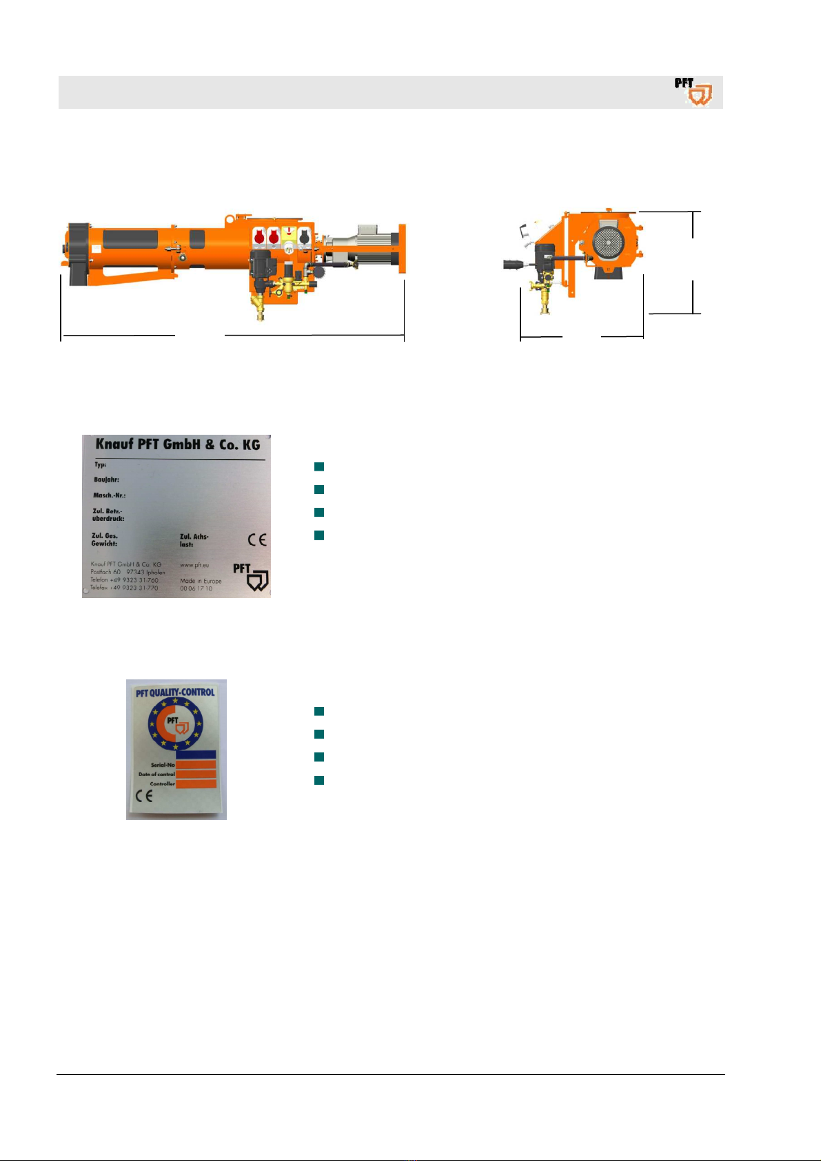
5
Dimension sheet for Lotus XL .................. 10
5.1 Type plate .............................................. 10
6
Quality control sticker ............................... 10
7
Design of LOTUS XL .................................. 11
7.1 Overview of LOT S XL silo light 400 V . 11
7.2 Overview of LOT S XL silo light 400 V
with water pump ................................ 12
8
Su assem lies ........................................... 13
8.1 Gear motor ............................................. 13
8.2 Middle body ............................................ 13
8.3 Mixing shaft / dosing shaft ..................... 13
8.4 Mixing tube with outlet ........................... 13
9
Description of su assem lies .................. 14
9.1 Overview of control unit without water
pump .................................................. 14
9.2 Overview of control unit with water
pump .................................................. 14
10
Connections ............................................... 15
10.1 Electrical connection ............................ 15
10.2 Water connection ................................. 15
11
Accessories ................................................ 16
11.1 Necessary accessories ........................ 16
11.2 Recommended accessories ................. 16
12
Brief description ......................................... 17
13
Material ........................................................ 18
13.1 Areas of application .............................. 18
14
Safety regulations ...................................... 19
15
Transport, packaging and storage ........... 19
15.1 Safety instructions for transport ........... 19
15.2 Transport checklist ............................... 20
15.3 Transport in individual parts ................. 20
15.4 Transportation of machines already
operating ............................................ 20
16
Packaging .................................................... 21
17
Operation ..................................................... 21
17.1 Safety ................................................... 21
18
Preparation of the machine ....................... 22
18.1 Fastening the LOT S XL to the silo ..... 23
18.2 Connection to the 400 V power supply 23
18.3 Checking the individual connector
plugs ................................................... 23
18.4 Water supply connection ...................... 24
18.5 Water from a water barrel ..................... 25
19
Setting the water factor ............................. 25
19.1 Presetting the water flow rate ............... 25
20
Putting the machine into operation .......... 26
20.1 Hazardous dust .................................... 26
20.2 Switching on the machine .................... 26
20.3 Changing the direction of rotation at
the main switch .................................. 27
21
Applying mortar .......................................... 28

PFT LOT S XL light 400 V Overview – Operation – Spare Parts Lists
Contents
4
2017-01-16
22
Interruption of work ................................... 28
23
Cleaning ...................................................... 28
23.1 Securing against restarting .................. 28
23.2 End of shift / Cleaning .......................... 29
23.3 Switching off the machine .................... 29
23.4 Removing the mixing tube ................... 29
23.5 Inserting the mixing shaft ..................... 30
24
Measures to e taken if there is a risk of
frost ............................................................. 30
25
Switching off in an emergency ................. 30
26
Trou leshooting ......................................... 31
26.1 Dealing with malfunctions .................... 31
26.2 Malfunctions ......................................... 32
26.3 Safety ................................................... 32
26.4 Table of malfunctions ........................... 33
27
Dealing with a power failure ..................... 35
28
Dealing with a water supply failure .......... 35
29
Maintenance ............................................... 35
29.1 Safety ................................................... 35
29.2 Cleaning ............................................... 36
29.3 Maintenance plan ................................. 36
30
Maintenance tasks ..................................... 37
30.1 Dirt trap sieve ....................................... 37
30.2 Sieve insert .......................................... 37
30.3 After performing maintenance .............. 37
31
Disassem ly ............................................... 38
31.1 Safety ................................................... 38
31.2 Disassembly ......................................... 39
31.3 Disposal ............................................... 39
32
Spare part drawing / spare part list,
LOTUS XL ................................................... 40
32.1 Spare part drawing of drive of LOT S
XL ...................................................... 40
32.2 Spare part list for drive of LOT S XL .. 41
32.3 Spare part drawing of middle body of
LOT S XL ......................................... 42
32.4 Spare part list for middle body of
LOT S XL ......................................... 43
32.5 Spare part drawing of mixing tube of
LOT S XL ......................................... 44
32.6 Spare part list for mixing tube of
LOT S XL ......................................... 45
32.7 Control unit of LOT S XL 50Hz, item
no. 00494837 ..................................... 46
32.8 Control unit of LOT S XL 50Hz item
no. 00494837 ..................................... 47
32.9 Control unit of LOT S XL 60Hz, item
no. 00500432 ..................................... 48
32.10 Control unit of LOT S XL 60Hz item
no. 00500432 ..................................... 49
32.11 Control unit of LOT S XL, item no.
00101848 ........................................... 50
32.12 Control unit of LOT S XS, item no.
00101848 ........................................... 51
33
Ca le set, Lotus XL light ooster pump
400 V / 50 Hz ............................................... 52
34
Ca le set, Lotus XL light 400 V / 50 Hz .... 53
35
Ca le set, Lotus XL light ooster pump
400 V / 60 Hz ............................................... 54
36
Check list for annual inspection y
specialist (master copy) ............................ 55
37
Index............................................................ 56

PFT LOT S XL light 400 V Overview – Operation – Spare Parts Lists
EC Declaration of Conformity
2017-01-16
5
1 EC Declaration of Conformity
Company: Knauf PFT GmbH & Co. KG
Einersheimer Straße 53
97346 Iphofen
Germany
declares, with exclusive responsibility, that the machine
Machine model: LOT S XL
Device type: Horizontal screw mixer
Serial num er:
Guaranteed sound power level: 78 dB
conforms to the following CE regulations:
• Outdoor Noise Directive (2000/14/EC),
• Machine Directive (2006/42/EC),
• Directive on Electromagnetic Compatibility (2014/30/EC).
Applied conformity assessment procedure according to Outdoor Noise Directive 2000/14/EC:
Internal manufacturing inspection as per Article 14, Section 2 in conjunction with Appendix V.
This declaration applies only to the machine in the condition it was in when sold. Components attached
or modifications undertaken by the end customer after purchase remain unconsidered. This declaration
becomes invalid if the product is converted or altered without approval.
Agent responsi le for putting together the relevant technical documentation:
Dipl.-Wirtsch.-Ing. Michael Duelli, Einersheimer Straße 53, 97346 Iphofen, Germany.
The technical documentation is held at:
Knauf PFT GmbH & Co.KG, Technische Abteilung, Einersheimer Straße 53, 97346 Iphofen, Germany.
Iphofen, Germany
Dr. York Falkenberg
General Manager
Place and date of issue
Name and signature
Information on signatory

PFT LOT S XL light 400 V Overview – Operation – Spare Parts Lists
Testing
6
2017-01-16
2 Testing
2.1 Testing y machine operator
Before the start of each work shift, the machine operator must test
the effectiveness of the control and safety devices as well as check
the proper attachment of all protective devices.
During operation, construction machines must be tested by the
machine operator for their operational safety.
If defects are found in the safety devices or any other area that
could impair safe operation, the supervisor must be notified
immediately.
For defects posing a hazard to persons, the operation of the
construction machine must be halted until the defect is eliminated.
2.2 Periodic inspection
Construction machines must be tested for safe operation by
a specialist as the usage conditions and operating circumstances
require, but at least once a year.
Pressure vessels must undergo the prescribed inspections by
authorised experts.
The inspection results are to be documented and must be stored at
least until the next inspection.

PFT LOT S XL light 400 V Overview – Operation – Spare Parts Lists
General information
2017-01-16
7
3 General information
3.1 Information regarding the operating manual
This manual provides important information and instructions on the
correct use of the equipment. Adherence to all defined safety and
handling instructions is a prerequisite for a safe working environment.
Additionally, the on-site accident prevention regulations and general
safety guidelines for the equipment must be followed at all times.
Read the manual carefully before starting any work! It is an integral
part of the product and must be kept near the machine and
accessible to operators at all times.
Always include the operating manual when transferring the machine
to third parties.
The diagrams and illustrations shown in the manual are intended
for better understanding of tasks and descriptions. They are not
necessarily shown to the correct scale and may vary slightly from
the actual equipment used.
3.2 Keep the manual for later use
The operating manual must be available during the entire service
life of the product.
3.3 Layout
The operating manual is comprised of two booklets:
Part 1: Safety
General safety instructions for HSM
Item number: 00 14 63 78
Part 2: Overview, operation, servicing and spare part lists
(this booklet).
Both parts must be read and adhered to in order to ensure safe
operation of the equipment. Together, they are valid as one
operating manual.
3.4 Spare part lists
You can find spare part lists for the machine in the Internet
under ww.pft.eu.

PFT LOT S XL light 400 V Overview – Operation – Spare Parts Lists
Technical data
8
2017-01-16
4 Technical data
4.1 General specifications
Item num er Specification Value
Unit
00103495 Weight 145,00
kg
00106142 Weight 141,00
kg
00491262 Weight 151.30
kg
00494491 Weight 151.30
kg
00500464
Weight 157,00
kg
Length 2,050
mm
Width 680 / 760
mm
Height 500 / 660
mm
4.2 Connected load
Output Setting value
Mixer motor 5.5 kW 11 A
Vibrator 0.25 kW 0.25 A
Water pump 0.5 kW 1.1 A
Electrical, 400 V
Specification Value
Unit
Voltage, AC current 50 Hz 400
V
Voltage, AC current 60 Hz 400
V
Max. current consumption 11
A
Max. power consumption 5.5
kW
Fuse 16
A
Mixer motor speed 280
rpm

PFT LOT S XL light 400 V Overview – Operation – Spare Parts Lists
Technical data
2017-01-16
9
4.3 Connection values for water
Fig. 1: Water connection
Specification Value
Unit
Operating pressure, min. 2.5
bar
Connection 1/2
inches
4.4 Operating requirements
Am ient conditions
Specification Value
Unit
Temperature range 2–45
°C
Relative humidity (maximum) 80
%
Operating period
Specification Value
Unit
Maximum continuous
operating period
8
hours
4.5 Sound power level
Guaranteed sound power level L
WA
78 dB (A)
4.6 Vi rations
Weighted effective acceleration value to which the upper limbs are exposed = < 2.5 m/s²
1

PFT LOT S XL light 400 V Overview – Operation – Spare Parts Lists
Dimension sheet for Lotus XL
10
2017-01-16
5 Dimension sheet for Lotus XL
Fig. 2: Dimensions
5.1 Type plate
Fig. 3: Type plate
The type plate contains the following information:
Manufacturer
Type
Year built
Machine number
6 Quality control sticker
Fig. 4: Quality control sticker
The quality control sticker contains the following information:
CE confirmed in compliance with E directives
Serial no. / serial number
Controlled by / signature
Date of control
760 2040
660

PFT LOT S XL light 400 V Overview – Operation – Spare Parts Lists
Design of LOTUS XL
2017-01-16
11
7 Design of LOTUS XL
7.1 Overview of LOTUS XL silo light 400 V
1 2 3 4 5 6 7 8 9 10
18 17 16 15 14 13 12 11
Fig. 5: Overvie of LOTUS XL silo light 400V
1. Mixing tube
2. Middle body
3. Crane eyelet for crane transport
4. Assembly aid for silo attachment
5. Silo connection flange
6. 230 V socket, continuous current
7. On/Off switch with phase inverter
8. Mixer motor connection (400 V)
9. Mixer motor
10. Motor swivel flange
11. Water connection on middle body (16)
12. Mains connection (400 V)
13. Water manifold
14. Water inlet, water connection from water supply
15. Vibrator connection (400 V)
16. Water connection to water manifold (11)
17. Mortar outlet
18. Front bearing

PFT LOT S XL light 400 V Overview – Operation – Spare Parts Lists
Design of LOTUS XL
12
2017-01-16
7.2 Overview of LOTUS XL silo light 400 V with water pump
1 2 3 4 5 6 7 8 9 10 11
20 19 18 17 16 15 14 13
Fig. 6: Overvie of LOTUS XL silo light 400V ith ater pump
1. Mixing tube
2. Middle body
3. Crane eyelet for crane transport
4. Assembly aid for silo attachment
5. Silo connection flange
6. Water pump connection (400 V)
7. Vibrator connection (400 V)
8. On/Off switch with phase inverter
9. Mixer motor connection (400 V)
10. Mixer motor
11. Motor swivel flange
12. Water connection on middle body (18)
13. Water manifold
14. Motor connection cable for water pump
15. Water outlet
16. Water pump
17. Water inlet, water connection from water supply
18. Water connection to water manifold (12)
19. Mortar outlet
20. Front bearing
12

PFT LOT S XL light 400 V Overview – Operation – Spare Parts Lists
Su assem lies
2017-01-16
13
8 Su assem lies
8.1 Gear motor
Fig. 7: Gear motor subassembly
The horizontal screw mixer PFT LOT S XL is comprised
of the following components:
Gear motor with motor swivel flange.
8.2 Middle ody
Fig. 8: Middle body
Middle body with dosing zone.
8.3 Mixing shaft / dosing shaft
Fig. 9: Mixing shaft
Mixing shaft / dosing shaft with coupling.
8.4 Mixing tu e with outlet
Fig. 10: Mixing tube ith outlet
Mixing tube with outlet.

PFT LOT S XL light 400 V Overview – Operation – Spare Parts Lists
Description of su assem lies
14
2017-01-16
9 Description of su assem lies
9.1 Overview of control unit without water pump
8 7 6 5 4 3
Fig. 11: Control unit of LOTUS XL
1. Mixer motor connection (400 V)
2. Pressure reducer
3. Water connection on middle body
4. Gauge for water pressure
5. Needle valve for setting water quantity
6. Water drain cock for freezing conditions
7. Water outlet
8. Stop cock
9. Connection to water supply network
10. Mains connection (400 V)
11. Main switch
12. Vibrator connection (400 V)
13. Socket (230 V), continuous current
9.2 Overview of control unit with water pump
11 10 9 8 7 6 5
Fig. 12: Control unit of LOTUS XL ith ater pump
1. Main switch
2. Mixer motor connection (400 V)
3. Mains connection (400 V)
4. Pressure reducer
5. Water connection on middle body
6. Gauge for water pressure
7. Needle valve for setting water quantity
8. Water drain cock for freezing conditions
9. Water outlet
10. Connection to water supply network
11. Motor connection cable for water pump
12. Water pump
13. Vibrator connection (400 V)
14. Water pump connection
1
2
13
12
11
10
9
1
2
3
4
14
13
12

PFT LOT S XL light 400 V Overview – Operation – Spare Parts Lists
Connections
2017-01-16
15
10 Connections
10.1 Electrical connection
Fig. 13: Electrical connection
1. Three-phase current connection (1), 400 V
10.2 Water connection
Fig. 14: Water connection ithout a booster pump
1. Water connection (1) from water supply network
or water barrel, without booster pump
Fig. 15: Water connection ith a booster pump
2. Water connection (2) from water supply network
with booster pump
1
2
1

PFT LOT S XL light 400 V Overview – Operation – Spare Parts Lists
Accessories
16
2017-01-16
11 Accessories
11.1 Necessary accessories
Fig. 16: Po er cable, 5 x 2.5, 25 m ith CEE plug and coupling 16 A, 6h red, item number 20423360
Po er cable, 5 x 2.5, 50 m ith CEE plug and coupling 16 A, 6h red, item number 20423350
Fig. 17: Water/air hose, 3/4" x 40 m, item no. 20212100
11.2 Recommended accessories
Fig. 18: Booster pump AV3000 ith handle 230 V / 50 Hz cpl., item no. 00130205
Fig. 19: Inlet strainer ith filter screen, stainless steel, cpl., item no. 00136619
Fig. 20: Spraying jet 3/4" ith Geka coupling, item no. 20215700

PFT LOT S XL light 400 V Overview – Operation – Spare Parts Lists
Brief description
2017-01-16
17
12 Brief description
Screw mixer
PFT LOTUS XL
The revolutionary mixing technique with decisive
advantages.
With its significant advantages the new horizontal
screw mixer PFT LOT S XL revolutionises mixing
technology.
The sturdy rubber mixing tube has already proved
itself in easy and quick cleaning of the PFT mixer.
nique is the new, revolutionary dosing and
mixing shaft, manufactured as a single unit without
a middle axle.
This type of construction is pointing the way:
No more deposits adhering, and the cleaning is
easier and faster than ever before.
The PFT LOT S XL has been developed for the
use of silo and container material: it mixes
continuously and fully automatically all premixed
dry lime/cement based mortars up to a grain size
of 8 mm.
An additional important advantage is the turnable
dosing segment. If replacement becomes necessary
due to wear, the segment can be turned 180° for
double use.

PFT LOT S XL light 400 V Overview – Operation – Spare Parts Lists
Material
18
2017-01-16
13 Material
13.1 Areas of application
SCREW MIXER
PFT LOTUS XL.
The revolutionary mixing technique with decisive
advantages.
AREAS OF APPLICATION: The PFT LOT S XL
mixes continuously and fully automatically all premixed
dry lime/cement based mortars up to a grain size
of 8 mm.
Bonding/reinforcing mortars
Masonry mortar
Jointing mortar
Plastering mortar
Screed mortar
Levelling compounds
and many more
Dry zone
Wet zone
Dry material

PFT LOT S XL light 400 V Overview – Operation – Spare Parts Lists
Safety regulations
2017-01-16
19
14 Safety regulations
Important!
When performing any work, observe the locally
applicable safety regulations for mortar conveying
and spraying machines!
15 Transport, packaging and storage
15.1 Safety instructions for transport
Improper transport
CAUTION!
Damage can e caused y improper transport!
Significant damage may occur if the equipment
is transported incorrectly.
– Proceed with care when unloading packages
and transporting goods on site. Always observe
the symbols and instructions on the packaging.
– Only use the suspension points provided.
– Only remove packaging shortly before
assembly.
Suspended loads
WARNING!
Danger of death due to suspended loads!
Falling or swinging parts can pose a fatal hazard
when heavy loads are lifted.
– Never step underneath suspended loads.
– Follow instructions regarding the suspension
points provided.
– Do not attach lifting tackle to protruding machine
parts or to eyelets of add-on components.
Ensure the lifting gear is fastened securely.
– Only use approved lifting gear and accessories
with a sufficient load-bearing capacity.
– Do not use torn or frayed ropes and belts.
– Do not attach ropes and belts to sharp edges
and corners. Do not knot or twist the ropes.

PFT LOT S XL light 400 V Overview – Operation – Spare Parts Lists
Transport, packaging and storage
20
2017-01-16
15.2 Transport checklist
Inspect the goods for damage and missing parts immediately after
delivery.
If external transportation damage can be seen, proceed as follows:
Do not accept the delivery, or accept it only under reservations.
Note the damage on the transportation documents or the delivery
note of the carrier.
NOTE!
Al ays submit a claim for the defects as soon
as they are detected. Damage claims can only be
accepted ithin the applicable deadlines for
submission.
15.3 Transport in individual parts
Fig. 21: Transport
To make transport easier, disassemble the machine
into its individual components:
1. Gear motor with motor swivel flange
2. Middle body with dosing zone
3. Mixing shaft / dosing shaft with coupling
4. Mixing tube with outlet
15.4 Transportation of machines already operating
Carry out the following steps before transporting:
1. First unplug the main power cable.
2. Remove the water supply lines.
3. Begin transport.
This manual suits for next models
5
Table of contents
Other PFT Mixer manuals