4. Installation
4.1 Controller
•Open Controller slot end cap and set jumper to correct pool voltage. The default is auto mode.
(On current models, the auto mode defaults to 24V. If the pool is other than 24V, set the jumper to
the correct pool voltage.)
•With power off, slide the yellow jumper off and place it back onto the Controller board in the desired
pool voltage location (position 1=12V, 2=24V, 3=36V, 4=48V, 5=72V, 6=80V) ensuring both pins
are inserted and the jumper is fully seated. We’ll confirm the setting by counting the number of blue
flashes on power up.
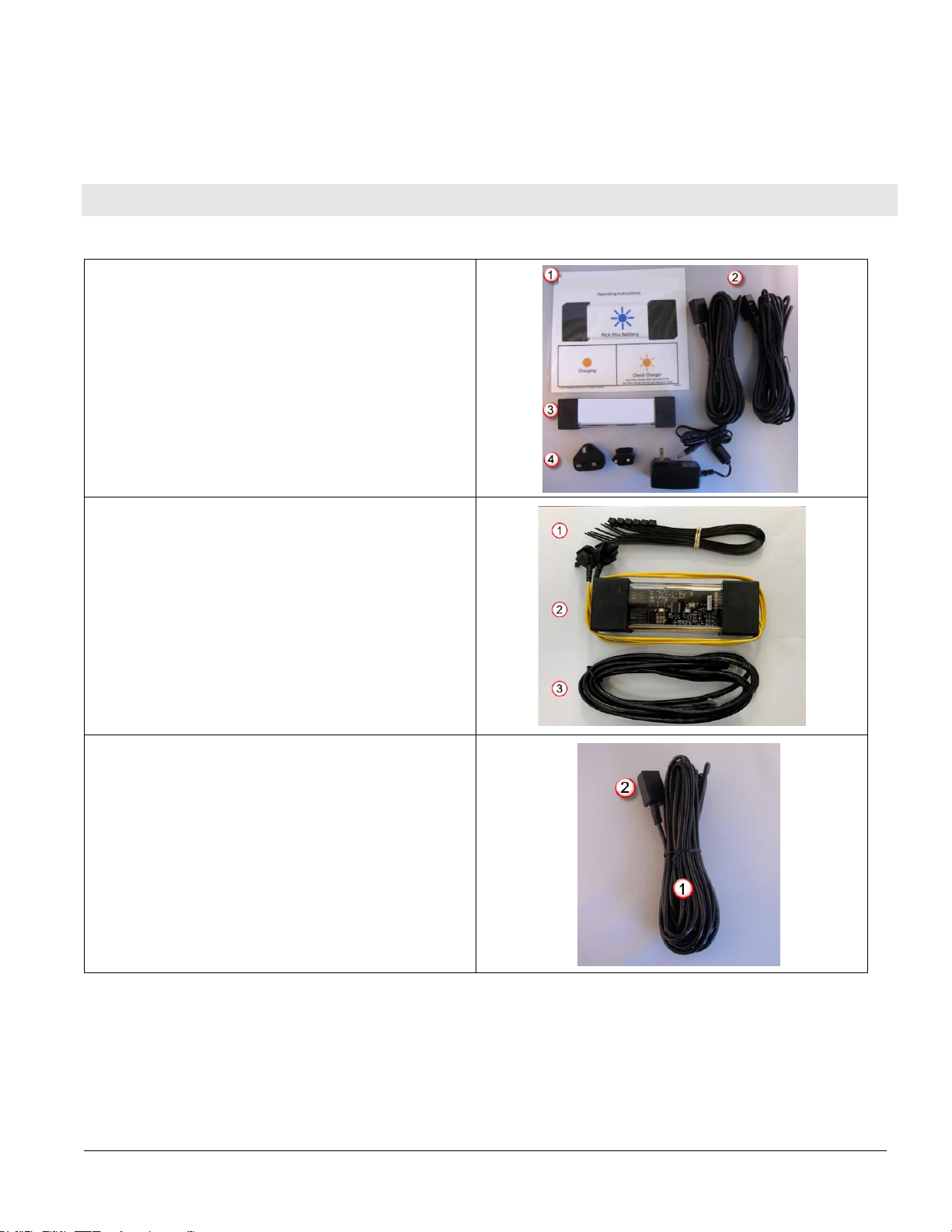
•Insert cable from the first Sentinel™through the Controller end cap and insert into its
communication socket.
•Insert power supply cable also through the end cap and plug into the receptacle on the Controller
board.
•Before mounting, hold the Controller where you can see through the side window, then plug in the
power.
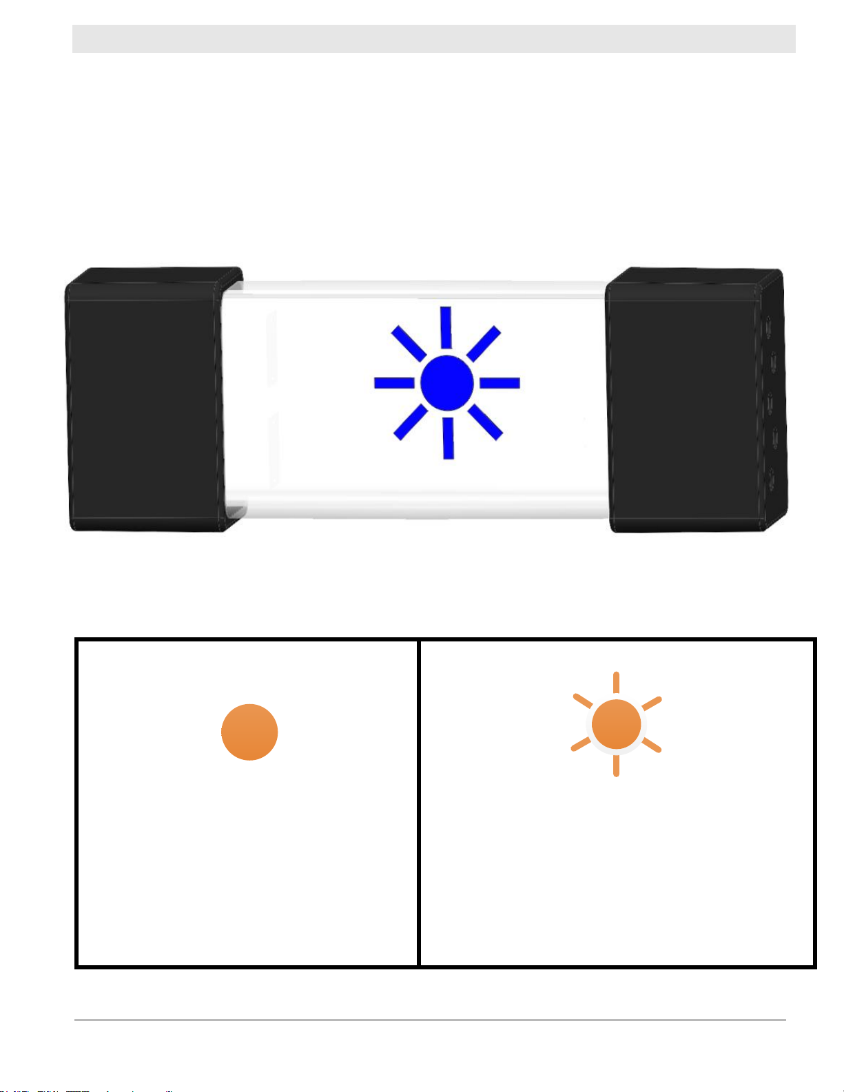
4.2 Voltage Confirmation Check
Upon initial power up, the Controller will test all 3 LED’s by illuminating them, then momentary pause and
begin to flash the blue LED by itself 0-6 times. The number of flashes indicates the voltage setting for the
Controller. For example, if you see 2 blue flashes the Controller is set for a 24V pool.
4.3 Sentinel™Install
•Open a Sentinel™on the slotted side by removing the slotted black end cap.
•Connect the cable provided
oPush the cable from the Controller through the concave end cap by squeezing the short
ends to help open the gap.
oClick the cable end into either of the communication sockets, tab down, and ensure it
clicks in securely.
oTake the cable from the next Sentinel™and do the same as above into the remaining
socket.
oSlide the wires through slotted black end cap and replace the cap on the Sentinel™
enclosure –you are now ready to mount the Sentinel™.
4.4 Mounting Sentinel™
•Included with each Sentinel™are cable ties that can be used to mount the Sentinel™and secure
the excess cable.
•Ensure the Sentinel™front (LED Component Side) is facing out and visible to the user.
•During the installation, it is a good idea to also secure the cable with the Sentinel™to provide a
strain relief on the data cable.
4.5 Connect Sentinel™Flexi-Tap to Charger DC Cable:
•The black Flexi-Taps have two sharp spikes protected by flexible tubing. Remove the tubing when
ready to install the Flexi-Taps.
•Connect one Flexi-Tap to a positive cable and one Flexi-Tap to a negative cable. Keeping the pin
centered on the cable, push the cable fully to the bottom of the recess of the Flexi-Tap allowing the
pins to completely penetrate the insulation and the DC charger cable.