manuals.online logo
Brands
  1. Home
  2. •
  3. Brands
  4. •
  5. Philco
  6. •
  7. Receiver
  8. •
  9. Philco 121 Reference manual

Philco 121 Reference manual

• • • • • • • • • •
SERVICE BULLETIN No. 306 lo, members of
RADIO MANUFACTURERS SERVICE
A PHILCO Service Plan
SPECIFICATIONS
TYPE OF CIRCUIT: A. C. operated; superheterodyne circuit
with three tuning ranges, covering standard broadcast (540 KC. to
1720 KC.)-police broadcast (1.7 MC. to 5.9 MC.) and short-wave
(5.8 MC. to 18.0 MC.) frequencies; Electric Push-Button tuning ;
Automatic Volume Control; and push-pull pentode output.
The receiver is designed to operate from a "Philco Safety
Aerial," part No. 40-6371. This aerial system should be used to
obtain maximum performance from the receiver.
POWER SUPPLY: Voltage, 115 volts. Frequency, 50-60 cycles.
Power consumption, 85 watts.
INTERMEDIATE FREQUENCY: 470 KC.
TUNING RANGES: 540 KC. to 1720 KC.; 1.7 MC. to 5.9 MC.;
5.8 MC. to 18.0 MC.
PHILCO TUBES USED: 1-78, R. F.; l-6A7, 1st detector and
oscillator; 1-78, I. F.; 1-6J5G, 2nd detector, Automatic Volume
Control; 1-6KSG, 1st audio ; l-6J5G, phase inverter; 2-42, push-
pull output; and 1-5Y4G, rectifier.
TUNING MECHANISM: Pulley and cable drive for manual
tuning. Electric Push-Button for Automatic tuning.
CABINETS: Type "XX."
Adjusting Electric Push-Button Tuning
In order to set the Electtic Push-Buttons correctly for each
station, the procedure as given below should be carefully followed.
Accurate adjustment of the buttons requires the use of a Philc o
Model 077 Station Setter and a part No. 27-7059 insulated screw
driver .
(A) Select eight of the most popular stations received in the
locality and remove their call letter s from the call letter sheets
supplied. Place the call letters in the windows above the buttons ,
making sure that each button covers the frequency of the station
for which it is to be used. Two adjustment screws for each button
are located on the rear of the push-button unit. Each set of screws
is numbered and covers a frequency range as follows:
Push-Button
I and 2
3 and 4
5 and 6
7 and 8
Frequency Range
540-1030 KC.
670-1160 KC.
900-1470 KC.
1100-1600 KC.
Looking at the front of the cabinet, the first button on the left is
adjusted by set screw No. 1, the next button by set screw No. 2,
and the remaining buttons in the same order.
(B) Connect the aerial and ground to the "ANT" and "GND"
terminals of the receiver.
(C) Turn the .receiver Tuning Range Selector to position 2
(Broadcast) and tune the receiver to the station to be set on the
first button .
(D) Plug the output leads of the Station Setter into the "High"
and "Gnd" jacks, and turn the output controls to maximum.
Turn the modulation control to "Modulation On." Connect the
output lead of the station setter to the "ANT" and "GND" ter-
minals of the receiver and tune to the frequency of the station
being received. As the indicator is slowly tuned thr ough the fre-
quency of the station, there will be two points at which a whistle
will be heard, one above and one below the frequency of the
station. When the indicator is on the frequency of the station
the whistle will be eliminated and the modulated signal of the
station setter wi.11then be clearly heard through the receiver .
(E) Turn the receiver Tuning Range Selector to position 1
( Push-Button) and press in the first button. Using the part No.
27-7059 insulated screw driver , turn the No. 1 "OSC" screw until
the broadcast station identified by the station setter signal is
tuned to Maximum Volume.
(F) Remove the output lead of the station setter from the
"ANT" terminal of the receiver and turn the indicator of the
station setter off the frequency of the station. The program of
the desired station will then be heard in the receiver without the
modulated signal.
(G) With the volume of the receiver low, slowly turn the No.
"OSC" screw back and forth until maximum output is .received.
Repeat the same procedure for the No. 1 "AN T" screw.
After setting up the first station, the same procedure given
under (C) to (G) is used for the other stations.
Copyright I938, Philco Radio & Television Corp.
Phila., Pa.
philcoradio.com
A/,ll I
SOLID R ING I NO I CA T(S , rR O ....T o r SW ITCH WAF(R.
SMAO( D A IN(. lNOIC "'-TCS R.EA_R or Sw1 !..f._~~~ -=
A B C ))
C3 D3 l z
0 0
40/1
OIR[ CTIQ N or ROTATIO N
fRO M R[AR or SWITCH.
~o!II ,m ... -
~
1-
6CHEMATIC DIAGRAM MODEL 39-45
~"rrJ~
@l"""
,g:!1.!'.Jt··j·i:·t
0)11.::Jc,@A:~Jcz@A~~~E3®A:,:lc.£,@)A::(,[2@A~:(,[~@A
0
A.sr;G[1@.)A
0
~~<.E2@).~~~()
philcoradio.com
@
.
.JOB
@)2NO.tE TIIANS-
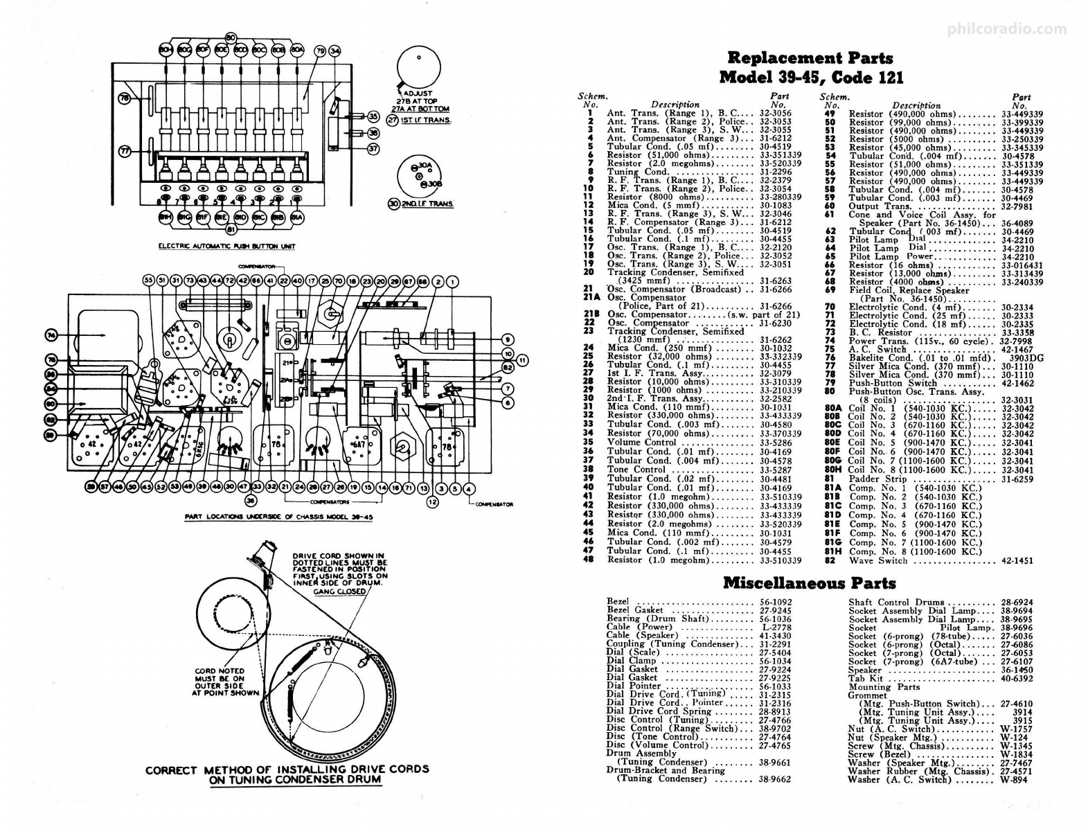
ELECTRICAUTOMATIC...... IUT'ltlN INT
IWIT LOCATIONSIH)[RSl0C Of C""SSIS M00CL Je-,O
OAIV[ CORO SHOWN IN
mlt~td~~s~~~o,:
r,~~.r
CORRECT METHOD or INSTALLING DRIVE CORDS
ON TUNING CONDENSER ORUM
Replacement Parts
Model 39-45, Code 121
Schem. Part
No.
32-3056
32-3053
32-3055
31-6212
30-4519
33-351339
33-520339
31-2296
32-2379
32-3054
33-280339
30-1083
32-3046
31-6212
30-4519
30-4455
32-2120
32-3052
32-3051
Schem. Part
No.
33.449339
33.399339
33.449339
33-250339
33-345339
30-4578
33-351339
33-449339
33-449339
30-4578
30-4469
32-7981
No.
1
2
3
4
5
6
7
8
9
10
11
12
13
14
15
16
17
18
19
20
21
21A
218
22
23
24
25
26
27
28
29
30
31
32
33
34
35
36
37
38
39
40
41
42
43
44
45
46
47
48
Description
Ant. Trans . (Range 1), B. C....
Ant. Trans. (Range 2), Police . .
Ant. Trans. (Range 3), S. W . . .
Ant. Compensator (Range 3) . . .
Tubular Cond. (.05 mf) .. ..... .
Resistor (51,000 ohms) . .... ... .
Resistor (2.0 megohms) ...... . .
Tuning Cond. . .. . ..... . ..... .
R. F. Trans. (Range 1), B. C... .
R. F. Trans . (Range 2) , Police ..
Resistor (8000 ohms) ......... .
Mica Cond . (5 mm£) .. .. . .. .. . .
R. F. Trans. (Range 3), S. W .. .
R. F. Compensator (Range 3) .. .
Tubular Cond. (.05 mf) . .... .. .
Tubul ar Cond . (.1 mf) . .. .. ... .
Osc. Trans . (Range I), B. C... .
Osc. Trans . (Range 2), Police .. .
Osc. Trans . (Range 3) , S. W.. . .
Tracking Condenser , Semifixed
(3425 mmf) .. . . . . . . . ... . . .. 31-6263
Osc. Compensat or (Broadcast) .. 31-6266
Osc . Compensator
(Police, Part of 21) . . . . . . . . . . 31-6266
Osc . Compensator. , . . ... . (s.w. part of 21)
Osc. Compensator ..... ... . . . . 31-6230
Tracking Condenser, Semifixed
(1230 mm£) . ; ... . .. ... .. . . .
Mica Cond . (250 mmf) .. . .... .
Resistor (32,000 ohms) ... .... .
Tubular Cond . (.1 mf) . .. . . . . . .
1st I. F. Trans. Assy .. . ... . .. . .
Resistor (10,000 ohms) . . .. .. . . .
Resistor (1000 ohms) . .. . . . ... .
2nd·L F. Trans . Assy .... . . .. .. .
Mica Cond. (110 mmf) . .. . . ... .
Resistor (330,000 ohms) ..... .. .
Tubular Cond. (.003 mf) ...... .
Resistor (70,000 ohms) . . . . . ... .
Volume Control ..... . .. ... . .. .
Tubular Cond. (.01 mf) ... ... . .
Tubular Cond . (.004 mf) . ... . . .
Tone Control . . . . . . .. . . ...... .
Tubular Cond. (.02 mf) .... . .. .
Tubular Cond . (.01 mf) .. ..... .
Resistor (1.0 megohm) . .. . .... .
Resistor (330,000 ohms) . . . .. . . .
ResistQr (330,000 ohms) ... .... .
Resistor (2.0 megohms) .. . . . .. .
Mica Cond. (I 10 mmf) . . ... .•..
Tubular Cond . (.002 mf) .... .. .
Tubular Cond. (.1 mf) .. .. ... . .
Resistor (1.0 megohm) ... .. ... .
31-6262
30-1032
33-332339
30-4455
32-3079
33-310339
33-210339
32-2582
30-1031
33-433339
30-4580
33-370339
33-5286
30-4169
30-4578
33-5287
30-4481
30-4169
33-510339
33-433339
33-433339
33-520339
30-1031
30-4579
30-4455
33-510339
No.
49
50
51
52
53
54
55
56
57
58
St
60
61
62
63
64
65
66
67
68
69
70
71
72
73
74
75
76
77
78
79
80
BOA
808
BOC
80D
BOE
BOF
BOG
IOH
81
81A
818
81C
81D
81E
81F
81G
81H
82
DescriPtion
Resistor (490,000 ohms) .. .. . .. .
Resistor (99,000 ohms) . . . .... . .
Resistor (490,000 ohms) .. . .... .
Resistor (5000 ohms) ....... . . .
Resistor (45,000 ohms) . .... .. . .
Tubular Cona . (.004 mf) . . . . ... .
Resistor (51 ,000 ohms) .. . . . .. . .
Resistor (490,000 ohms) . . .. . .. .
Resistor (490,000 ohms) . . ... . . .
Tubular Cond. (.004 mf) . . . .. . .
Tubular Cond. (.003 mf) . .. ... .
Output Trans . . ...... ... . . .. . .
Cone and Voice Coil Assy . for
Speaker (Part No. 36-1450) .. . 36-4089
Tubular Co°'!) <003 mf). . . . . . . 30-4469
Pilot Lamp 1~1• • • • • • • • • • • . • . 34-2210
Pilot Lamp Dial . . ....•. . .... . 34-2210
Pilot Lamp Power .. . . .. . .. .... 34-2210
Resistor (16 ohms) . ........... 33-016431
Resistor ( IJ,000 ohms) .. . ...... 33-313439
Resistor (4000 ohms) . . . . . . . . . . 33-240339
Field Coil, Replace Speaker
(Part No . 36-1450) .. .... .. . .
Electrolytic Cond. (4 mf) . . . . . . . 30-2334
Electrolytic Cond. (25 mf) . . . . . . 30-2333
Electrolytic Cond . (18 mf) . . .... 30-2335
B. C. Resistor . . . . . . . . .. . . . . . . 33-3358
Power Trans . (1 l 5v., 60 cycle) . 32-7998
A. C. Switch ... . ........ ... .. 42-1467
Bakelite Cond. (.01 to .01 mfd). 3903DG
Silver Mica Cond. (370 mmf) . .. 30-1110
Silver Mica Cond . (370 mmf) . . . 30-1110
Push•Button Switch .... . . ..... 42-1462
Push-Button Osc. Trans. Assy.
(8 coils) . . . . . . . . . . . . . . . . . . . 32-3031
Coil No. 1 (540-1030 KC.) ..... 32-3042
Coil No. 2 (540-1030 KC.) .. . . . 32-3042
Coil No . 3 (670-1160 KC .) .. . .. 32-3042
Coil No. 4 (670 -1160 KC.) . .. .. 32-3042
Coil No. 5 (900-1470 KC.)., ... 32-3041
Coil No.. 6 (900-1470 KC.) ..... 32-3041
Coil No. 7 (1100-1600 KC.) ..... 32-3041
Coil No. 8 (1100-1600 KC.) . . . . . 32-3041
Padder Strip .... . .. .... .. .. .. 31-6259
Comp. No. 1 (540-1030 KC.)
Comp. No. 2 (540-1030 KC .)
Comp. No. 3 (670-1160 KC.)
Comp. No. 4 (670 -1160 KC.)
Comp. No. 5 (900-1470 KC.)
Comp. No. 6 (900•1470 KC.)
Comp. No. 7 (1100-1600 KC.)
Comp. No. 8 (1100-1600 KC.)
Wave Switch . ... .. .. .... ..... 42-1451
Miscellaneous Parts
Bezel ... ... .. ... .... ... . .. ... 56-1092
Bezel Gasket . . . . . . . . . . . . . . . . . 27-9245
Bearing (Drum Shaft) .. .. .. ... 56-1036
Cable (Power) . . . . . . . . . . . . . . . L-2778
Cable (Speaker) ... . ..... . .... 41-3430
Coupling (Tuning Condenser) .. . 31-2291
Dial (Scale) .... . . .. .. . ... . ... 27-5404
Dial Clamp .. ..... .. . . ...... .. 56-1034
Dial Gasket ......... ... . ... .. 27-9224
Dial Gasket . . . . . . . . . . . . . . . . . . 27-9225
Dial Pointer .. .. . . .. .... . .. ... 56-1033
Dial Drive Cord . (Tuning) . .... 31-2315
Dial Drive Cord .. Point er . . . . . . 31-2316
Dial Drive Cord Spring ... .. .. . 28-8913
Disc Control (Tuning) . . .. .... . 27-4766
Disc Control (Range Switch) . . . 38-9702
Disc (Tone Control) ... ..... . . . 27-4764
Disc (Volume Control) . ... . . .. . 27-4765
Drum Assembly
(Tuning Condenser) . . . . . . .. 38-9661
Drum-Bracket and Bear ing
(Tuning Condenser) ... ... .. 38-9662
Shaft Control Drums ... . . . .. . .
Socket Assembly Dial Lamp ... .
Socket Assembly Dial Lamp . .. .
Socket Pilot Lamp .
Socket (6-prong) (78-tube) . .. . .
Socket (6-prong) (Octal) .... . . .
Socket (7-prong) (Octal) ... ... .
Socket (7-prong) (6A7-tube) . . .
Speaker .. . . ... . ..... . . .. . . . . .
Tab Kit . ..... . . .. ........ . .. .
Mounting Parts
Grommet
(Mtg . Push-Button Switch) .. .
(Mtg . Tuning Unit Assy.) . . . .
(Mtg . Tunin~ Unit Assy .) . . . .
Nut (A . C. Switch) .. .. . .. ... . .
Nut (Speaker Mtg.) ...... . ... .
Screw (Mtg. Chassis) .. . ...... .
Screw (Bezel) . . . ..... . . ..... .
Washer (Speaker Mtg.) .... .. . .
Washer Rubber (Mtg. Chassis).
Washer (A. C. Switch) .... . . . .
28-6924
38-9694
38-9695
38-9696
27-6036
27-6086
27-6053
27-6107
36-1"50
40-6392
27-4610
3914
3915
W-1757
W-124
W-1345
W-1834
27-7467
27-4571
W-894
philcoradio.com
Alignment of Compensators
EQUIPMENT REQUI RED :
( 1) Signal Generator; Philco Model 077 Signal Generator which
has a fundamental frequency range from 115 to 36,000 KC. is the
correct instrument for this purpose.
OUTPUT METER: The Philco 027 Output Meter is connected
to the plate terminals of the type 42 tubes and adjusted for the
0 to 30 V. A. C. scale. After connecting the output meter, adjust
the compensators in the order as shown in the tabulation below.
Locations of the compensators are shown on page 3. If the output
meter pointer goes off scale when adjusting the compensators,
reduce the streng th of the signal from the generator.
(2) Output meter, Philco Model 027 Circuit Tester, incorporates
a sensitive output meter and is recommended.
(3) Philco Fiber Handle Screw Driver, part No. 27-7059 and
Fiber Wrench, part No. 3164.
SIGNAL GENERATOR RECEIVER
Opera• Specia l
tion Output Dunimy Adjust Instruc-
Connections Antenna Dial Dial Contro l Compensators tions
to Receiver (Note A) Setting Setting Setting to Max . Reading
1 6A7 .1 mf 470 KC. 470 KC. Vol. Max. 30B, 30A,
Range Switch 27B, 27A
Broadcast
2 Antenna 150mmf 1550KC. 15SOKC. " 21, SB, SA See Note
BandC
3 Antenna 150mm£ 580 KC. 580 KC. " 22 Roll
Tuning
Condenser
4 Antenna 150mmf 1550KC. 1550KC. " 21
5 Antenna 400ohms 5.0MC. 5.0MC. Range Switch 21A
Police
6 Antenna 400 ohms 18.0MC. 18.0MC. Range Switch 21B, 14,4
S.W.
NOTE A- The "Dummy Antenna" consists of a condenser connected in
series with th e signal generator output lead (high side). Use the capacity
as specified in each step of the above procedure.
capacity), set the dia l pointer on the extreme left index line at the low
frequency end of the broadcast sc-:tle. The arrangement of the drive cable
is shown on page 3.
NOTE B- Dial Calibration: In order to adjust the receiver correctly the
dial must be aligned to track properly with the tuning condenser. To adjust
the dial, proceed as follows: With the tuning condenser closed (maximum
NOTE C- Compensators (SA) and (SB) are located on top of the tuning
condenser. Compensator (SA) is the first one from the tuning drum side.
PHILCO VACUUM TUBE VOLTMETER AND CIRCUIT TESTER
Model 027 For A. C. Operation
Every service test can be made on this new Philco 027 combination Vacuum Tube
Voltmeter and Circuit Tester, with a speed, accuracy and simplicity available in no
other unit designed for a similar purpose .
The vacuum tube voltmeter (infinite ohms per volt) provides extreme accuracy on
the low range voltages-for checking grid voltages, automatic volume control circuits,
gain per stage measurements and making other delicate tests of which an ordinary
voltmete r or "analyzer" is completely incapable. In addition to performing such pre-
cision tests, all ordinary tests of voltage, current, resistance, capacity and output in a
receiver, are provided.
A revolutiona ry feature of the 027 is the automatic push-button design for selecting
the type of test and range desired. Eliminates rotary switches, jacks, plugs, etc., and
saves time on alltests. Different colored selector buttons tie in with similarly colored
scale identifications.
Other features of this outstanding new unit are- new large SQUARE type meter
(4¼"x 4¾") with exceptionally easy reading scales ; extra high range ohmmeter (0 to
150 megohms); new type test prods with replaceable points; pilot lamp on vacuum
tube voltmeter. Rugged construction throughout; matches other Philco test units in
size and general appearance .
Net Dealer Price • • • • • • • • ,4zoo
PHILCO RADIO AND TELEVISION CORPORATION
Philadelphia, Pa.
Parts and Service Division
August, 1938 Printed in U.S. A.
philcoradio.com

Other manuals for 121

8

This manual suits for next models

1

Other Philco Receiver manuals

Philco 76 User manual

Philco

Philco 76 User manual

Philco 30 User manual

Philco

Philco 30 User manual

Philco 45 User manual

Philco

Philco 45 User manual

Philco 38-116 Reference manual

Philco

Philco 38-116 Reference manual

Philco 39-85 Reference manual

Philco

Philco 39-85 Reference manual

Philco 38 User manual

Philco

Philco 38 User manual

Philco 50 User manual

Philco

Philco 50 User manual

Philco 41 User manual

Philco

Philco 41 User manual

Philco 37-61 Reference manual

Philco

Philco 37-61 Reference manual

Philco 34 User manual

Philco

Philco 34 User manual

Philco 95 User manual

Philco

Philco 95 User manual

Philco 39-25 Reference manual

Philco

Philco 39-25 Reference manual

Philco 38-14 Reference manual

Philco

Philco 38-14 Reference manual

Popular Receiver manuals by other brands

Marantz 2275 Service manual

Marantz

Marantz 2275 Service manual

Sony HCD-SLK1i - Dvd Receiver Service manual

Sony

Sony HCD-SLK1i - Dvd Receiver Service manual

Sony STR-DH500 Quick setup guide

Sony

Sony STR-DH500 Quick setup guide

STONEX S9i user manual

STONEX

STONEX S9i user manual

Becker Centronic VarioControl VC421 Assembly and operating instructions

Becker

Becker Centronic VarioControl VC421 Assembly and operating instructions

Elk Products ELK-M1XRF319 installation manual

Elk Products

Elk Products ELK-M1XRF319 installation manual

Philips UPC Direct DSR4101/58 user manual

Philips

Philips UPC Direct DSR4101/58 user manual

GTO RB709U-NB owner's manual

GTO

GTO RB709U-NB owner's manual

Atron 5000 owner's manual

Atron

Atron 5000 owner's manual

Alpine CDA-9835R Service manual

Alpine

Alpine CDA-9835R Service manual

EPH Controls RF1A-OT operating instructions

EPH Controls

EPH Controls RF1A-OT operating instructions

Kenwood KR-X1000 Setting up

Kenwood

Kenwood KR-X1000 Setting up

LG HT953TV Service manual

LG

LG HT953TV Service manual

Marmitek 3856S quick guide

Marmitek

Marmitek 3856S quick guide

DELTA DORE AC 51115 quick start guide

DELTA DORE

DELTA DORE AC 51115 quick start guide

Harman Kardon AVR 245 Worksheet

Harman Kardon

Harman Kardon AVR 245 Worksheet

JK Audio Broadcast Host user guide

JK Audio

JK Audio Broadcast Host user guide

Strong SRT 4922A user manual

Strong

Strong SRT 4922A user manual

manuals.online logo
manuals.online logoBrands
  • About & Mission
  • Contact us
  • Privacy Policy
  • Terms and Conditions

Copyright 2025 Manuals.Online. All Rights Reserved.