manuals.online logo
Brands
  1. Home
  2. •
  3. Brands
  4. •
  5. Philco
  6. •
  7. Receiver
  8. •
  9. Philco 30 User manual

Philco 30 User manual

'
' '
-
.
-~~
.. -....
...--
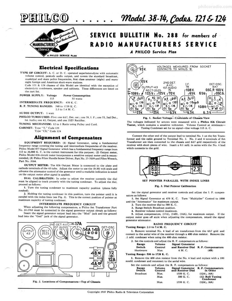
Radio Service Bulletin-No. 2,9
Model 30 Receiver
The Model 30 Receiver is designed for use with the latest 2-volt filament
type tubes only.
Table 1-Tube Socket Readings Taken with Average Set Checker
Filament Plate Grid Plate Screen
Tube Circuit Volts Volts Volts Current Grid
Milliamperes Volts
32 1st R. F. 2.0 150 .. .0015 60
32 2d R. F. 2.0 150 .. .0015 58
32 3d R. F. 2.0 150 .. .0015 58
30 Detector Rectifier 2.0 ... . . .... ..
30 Detector Amplifier 2.0 15 . . .. . . ..
30 1st Audio 2.0 90 Note I .002 ..
31 {2d Audio} 2.0* 150 24 .008 ..
31 Push-Pull 2.0* 150 24 .008 ..
*These readings reversed with respect to other Filament Voltage readings.
NOTE1. With volume control in "Off" position, approximately 4 volts; with volume control
full on, less than I volt.
Always use high-resistance voltmeter, preferably 1000 ohms per volt, when checking voltages
in the Receiver. For reading plate and screen voltages, use a 250- or 300-volt scale. Voltage readings
taken with meters having less than 250,000 ohms resistance will be lower than voltages given in the table.
When testing a Model 30 Receiver, all tubes must be in their proper sockets. The speaker must
be connected and the tube shield must be fastened in place. The readings in Table I were taken using
"A," "B" and "C" batteries.
Table 2-Resistor Data Table 3-Condenser Data
No.on Color Resistance No.on Capacity- MFD.
Figs. I and 2 Ohms Figs. I and 2
0 Golden Yellow 5,000 ® .00005
@) Auto Buff 25,000 @ @ .000250
® Jade Green 70,000 @ .01
@ ® Silver Gray 100,000 ® ® @) .05
@ White 250,000 @ @ @) ® .05 with 250-ohm resistor
@) @ @ Battleship Gray 500,000 winding
@ Tubular {250 @) .25 single section
(two section) 800 @ .25 two sections
philcoradio.com
GND.ANT.
~
INDICATES
CHASSIS
t
)
32
Model 30
32 32 30
/----------,-------,-. -----
C·3V C+
'sLACKWHITE
WITH
WHITE
TRACER
f@
C·3V. C+
,.._,-._ ,...,..____
BLACKGREEN
WITH
GREEN
TRACER
"f~
"f®
B+90V
-
YELLOW
WITH
BLACKTRACER
Fta. l
' )
B+l80V
YELLOW
31
~
~rrSPEAKER PLUGAND
SOCKET SHOWN
-00--
A+ A· B-
,.....,._-------
RED BLACK BLACK
WITH
YELLOW
)
'
l
•
..
•
i
'
i
i
f
N
•
philcoradio.com
t )
I
2ND AUDIO
(PUSH-PULL)
TUBE SOCKETS
1ST AUDIO
TUBE
SPEAKER DETECTOR
SOCKET AMPLIFIER
)
Model 30
DETECTOR RF TUBE SOCKETS
RECTIFIER
TUBE SOCKET TUBE SOCKET Fill.2
,}
•
J
I
~
t
fl)
fD
~
.. .!•I
~
-·
ft
fD '!JU
f
=fD
..
S'
..
i
\II
philcoradio.com
~
Paae4 Racllo Service Bulletin
COMPENSATING
Compensate the Model 30 in the usual manner. Use a good D.C. oscillator for the R. F. signal,
connecting the oscillator lead to the ANT terminal of the Receiver. A good ground should be con-
nected to the GND terminal of the Receiver.
Either the ear method or an output meter can be used while adjusting.
With the Receiver set up for operation, adjust the oscillator signal to a frequency between 1200
and 1300 kilocycles. This corresponds to 120 and 130 on the Receiver tuning scale.
Use a weak signal and tune the Receiver sharply to the oscillator note. The volume control should
be turned on "full." · ·
Adjust the compensating condensers, starting with the fourth condenser @ in (Fig. 2.) If using
the ear method, adjust the condenser to the loudest signal. If using an output meter, adjust for the
maximum reading.
Next adjust the third, then the second, and finally the first. It will not be necessary to reduce
the oscillator signal as the successive condensers are adjusted. Reduce the volume of the Receiver with
the volume control.
In each step, always adjust for the maximum signal or reading.
REPLACEMENT PARTS LIST
No.on
Figs.land 2 Description
CDResistor (5000)
® Antenna Coil .
@ By-Pass Condenser (.05)
© Tuning Condenser
© Compensating Condenser
® Resistor (70,000)
® Coupling Condenser .
® Coil-2d R. F.
® By-Pass (.05)
@ Compensating Condenser
@ By-Pass Condenser (.05) and
Resistor.
@ By-Pass Condenser (.05) and
Resistor.
@ Coupling Condenser .
@ Coil-3d R. F.
@ By-Pass Condenser (.05)
@ Compensating Condenser
@ Coupling Condenser .
@ Coil-4th R. F.
@ Resistor (500,000)
@) By-Pass Condenser (.05) and
Resistor.
@ By-Pass Condenser (.05) and
Resistor.
@ By-Pass Condenser (Double .25)
@ Filter Choke .
@ Condenser (.00005)
@ Compensating Condenser
@ Resistor (100,000)
Part No.
3526
4182-A
3615-E
4000-G
3968-A
3542
3892-A
4182-B
3615-E
3968-A
3615-B
3615-C
3892-A
4182-B
3615-F
3968-A
3892-A
4182-B
3769
3615-C
3615-B:
3557
3518
3774
3772-A
3767
No.on
Fi!1,s.1arid 2 Description .
® Resistor (100,000)
@ Resistor (250,000)
® Resistor (500,000)
@ By-Pass Condenser (.000250)
® By-Pass Condenser (.000250)
@ Resistor (500,000)
@ By-Pass Condenser (.01)
® Volume Control
@ Resistor
@ On-Off Switch
@) Tone Control
@ Audio Transformer
@) By-Pass Condenser (Single .25)
@ Resistor (25,000)
@ Speaker Motor
@ Cone Assembly
Speaker Cord and Plug
Knob (Large).
Knob (Small) .
Spring (For 3579 and 3580) .
Knob (Switch)
Spring (For 4146)
Tuning Scale .
Grid Clip .
"A" Battery (2-volt) "Philco
Drynamic 92-R"
Tube Socket (32 type tube)
Assembly
Tube Socket .
Speaker Socket
PHILADELPHIA STORAGE BATTERY COMPANY
Ontario and C Streets, Philadelphia, Pa.
Part No.
3767
3768
3769
3082
3082
3769
3903-F
4093
3864
4095
4037-A
3242
4264
3656
2761
2764-A
L-1127-A
3580-A
3579-A
3305
4146-A
4147
4139
4060-A
3977-C
3977-A
3977-B
August, 1930 Form No. 2436 Printed in U.S. A.
philcoradio.com

Other Philco Receiver manuals

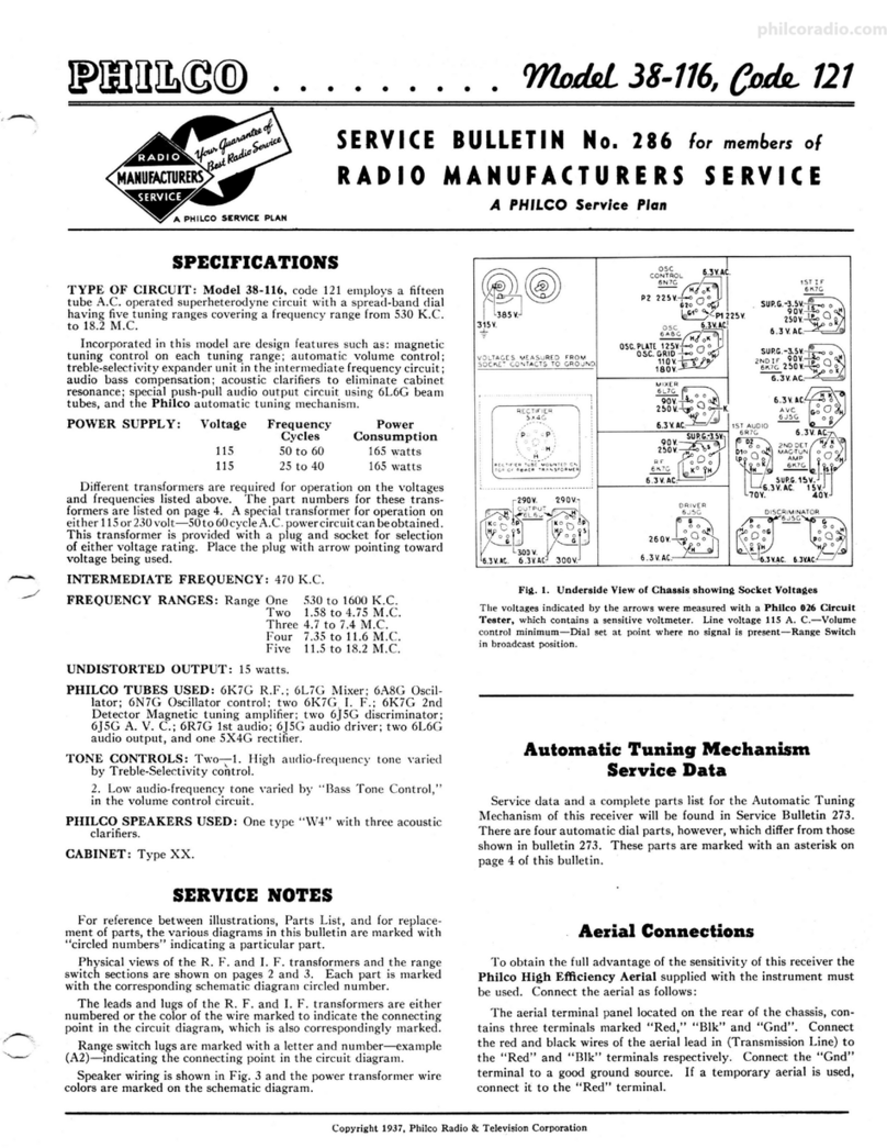
Philco 38-116 Reference manual

Philco

Philco 38-116 Reference manual

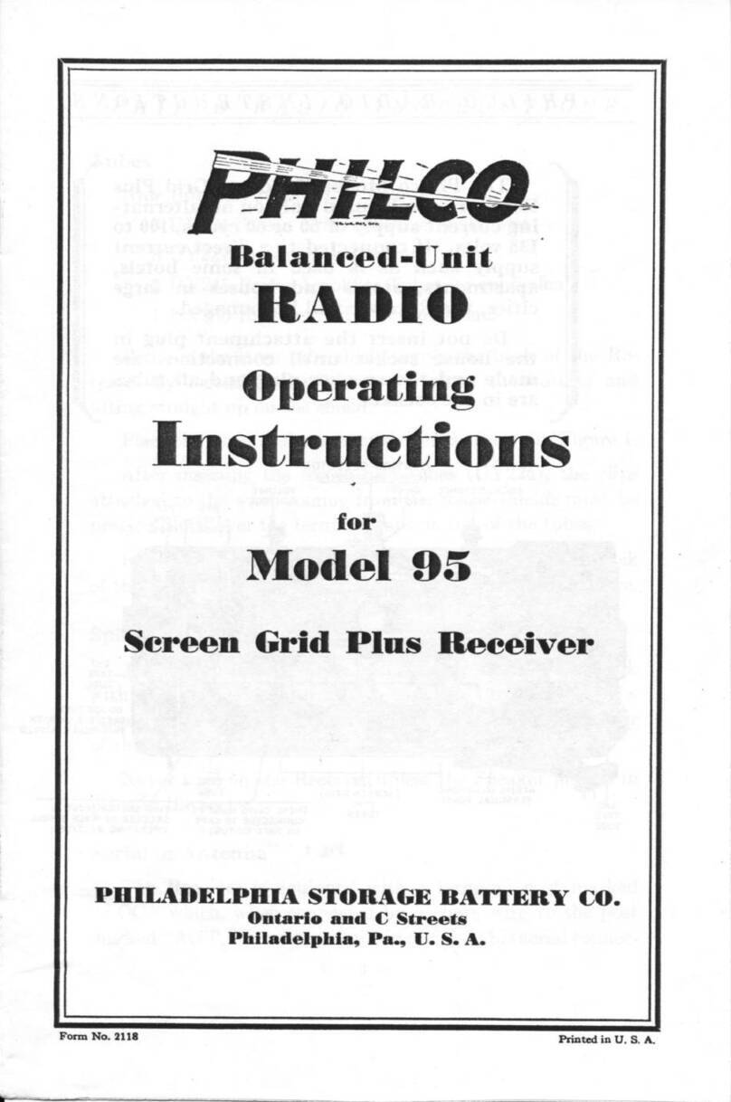
Philco 95 User manual

Philco

Philco 95 User manual

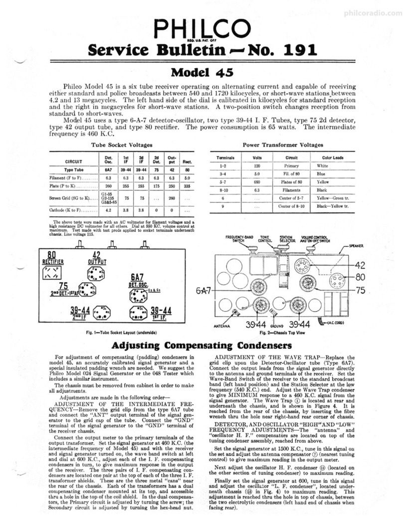
Philco 45 User manual

Philco

Philco 45 User manual

Philco 37-61 Reference manual

Philco

Philco 37-61 Reference manual

Philco 41 User manual

Philco

Philco 41 User manual

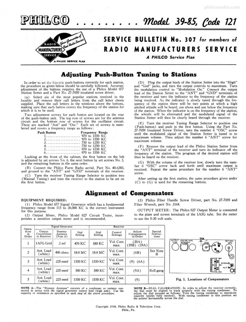
Philco 39-85 Reference manual

Philco

Philco 39-85 Reference manual

Philco 38 User manual

Philco

Philco 38 User manual

Philco 50 User manual

Philco

Philco 50 User manual

Philco 34 User manual

Philco

Philco 34 User manual

Philco 38-14 Reference manual

Philco

Philco 38-14 Reference manual

Philco 76 User manual

Philco

Philco 76 User manual

Philco 121 Reference manual

Philco

Philco 121 Reference manual

Philco 39-25 Reference manual

Philco

Philco 39-25 Reference manual

Popular Receiver manuals by other brands

JTS TG-10STX user manual

JTS

JTS TG-10STX user manual

Quantum Q10 quick guide

Quantum

Quantum Q10 quick guide

Thrane&Thrane TT-3080A user manual

Thrane&Thrane

Thrane&Thrane TT-3080A user manual

Audio Pro RXD200 owner's manual

Audio Pro

Audio Pro RXD200 owner's manual

TV Star T2 517 user manual

TV Star

TV Star T2 517 user manual

Onkyo TX-NR1007 instruction manual

Onkyo

Onkyo TX-NR1007 instruction manual

TerraTec CINERGY MOBILE WIFI TV quick start guide

TerraTec

TerraTec CINERGY MOBILE WIFI TV quick start guide

FUTABA R204GF-E user manual

FUTABA

FUTABA R204GF-E user manual

Navilock u-blox 8 NEO-M8U Operation manual

Navilock

Navilock u-blox 8 NEO-M8U Operation manual

RST Instruments RSTAR L900 Series instruction manual

RST Instruments

RST Instruments RSTAR L900 Series instruction manual

Quark-Elec QK-A027 manual

Quark-Elec

Quark-Elec QK-A027 manual

JAMO DMR 60 instructions

JAMO

JAMO DMR 60 instructions

Rextron Toughbook Arbitrator HD S9-900TX user guide

Rextron

Rextron Toughbook Arbitrator HD S9-900TX user guide

CYP 5-Play HDBaseT PU-507WPRX Operation manual

CYP

CYP 5-Play HDBaseT PU-507WPRX Operation manual

Gilbarco TRIND Start-up, Service and Parts Manual

Gilbarco

Gilbarco TRIND Start-up, Service and Parts Manual

Yamaha RX-A2020 quick guide

Yamaha

Yamaha RX-A2020 quick guide

Yamaha rx-sl100 Service manual

Yamaha

Yamaha rx-sl100 Service manual

Jobsite IR-WMR Installation and user guide

Jobsite

Jobsite IR-WMR Installation and user guide

manuals.online logo
manuals.online logoBrands
  • About & Mission
  • Contact us
  • Privacy Policy
  • Terms and Conditions

Copyright 2025 Manuals.Online. All Rights Reserved.